


Ä
(2)Remove nuts holding bumper fascia to quarter panels.
(3)Remove fasteners holding bumper fascia to wheel opening flange.
(4)Disconnect license plate lamp wire connectors.
(5)Remove bolts holding bumper to rear closure panel.
FRAME AND BUMPERS 13 - 9
(6)Remove nuts holding bumper to energy absorber units.
(7)Separate bumper from vehicle.
REAR BUMPER INSTALLATION
Reverse the preceding operation.
FRAME
INDEX
|
page |
|
page |
Crossmember . . . . . . . . . . . . . . . . . . . . . . . . . . |
. 17 |
General Information . . . . . . . . . . . . . . . . . . . . . . |
. . 9 |
Frame Dimensions . . . . . . . . . . . . . . . . . . . . . . . |
. . 9 |
|
|
GENERAL INFORMATION
In this section, references are made to Vehicle Family (Body) codes. To determine the vehicle family identification code, refer to the Introduction Group at the front of this manual.
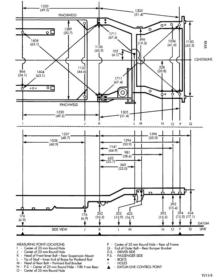
FRAME DIMENSIONS
Frame dimensions are listed in metric scale then converted to inch scale listed in parenthesis. Engine compartment charts include front suspension upper strut damper mounting tower location. All dimensions are from center to center of Principal Locating Point (PLP), or from center to center of PLP and fastener location.
VEHICLE PREPARATION
Position the vehicle on a level work surface. Using screw or bottle jacks, adjust the vehicle height to the specified PLP dimension above the Datum Line (work surface). Vertical dimensions can be taken from the datum line to the PLP.
ENGINE COMPARTMENT DIMENSIONS
Fig. 1 Engine Compartment DimensionsÐAA-Body
Refer to Fig. 1, 2, 3, 4 or 5.
FRONT FRAME DIMENSIONS
Refer to Fig. 6
REAR FRAME DIMENSIONS
Refer to Fig. 7, 8, 9, 10 or 11.

13 - 10 FRAME AND BUMPERS |
|
Ä |
|
Fig. 2 Engine Compartment DimensionsÐAC-Body |
Fig. 4 Engine Compartment DimensionsÐAJ-Body |
Fig. 5 Engine Compartment DimensionsÐAP-Body
Fig. 3 Engine Compartment DimensionsÐAG-Body
Ä |
|
FRAME AND BUMPERS 13 - 11 |
|
Fig. 6 Front Frame DimensionsÐAll

13 - 12 FRAME AND BUMPERS |
|
Ä |
|
Fig. 7 Rear Frame DimensionsÐAA-Body
Ä |
|
FRAME AND BUMPERS 13 - 13 |
|
Fig. 8 Rear Frame DimensionsÐAC, AY-Body

13 - 14 FRAME AND BUMPERS |
|
Ä |
|
Fig. 9 Rear Frame DimensionsÐAG-Body

Ä |
|
FRAME AND BUMPERS 13 - 15 |
|
Fig. 10 Rear Frame DimensionsÐAJ-Body

13 - 16 FRAME AND BUMPERS |
|
Ä |
|
Fig. 11 Rear Frame DimensionsÐAP-Body