- •EVAPORATIVE EMISSION CONTROLS
- •VACUUM SCHEMATICS
- •EVAPORATION CONTROL SYSTEM
- •EVAPORATIVE CANISTER
- •CANISTER PURGE SOLENOID
- •POSITIVE CRANKCASE VENTILATION (PCV) SYSTEMS
- •PCV VALVE TEST
- •CRANKCASE VENT FILTER
- •EXHAUST EMISSION CONTROLS
- •HEATED INLET AIR SYSTEM
- •HEATED INLET AIR SYSTEM SERVICE
- •HEATED OXYGEN SENSOR (O2 SENSOR)
- •REMOVAL
- •EXHAUST GAS RECIRCULATION (EGR) SYSTEM
- •EGR GAS FLOW TEST
- •REMOVAL
- •INSTALLATION
- •REMOVAL
- •INSTALLATION
- •REMOVAL
- •INSTALLATION
- •REMOVAL
- •INSTALLATION
- •REMOVAL
- •INSTALLATION
- •EGR DIAGNOSIS CHART
- •AIR ASPIRATION SYSTEM
- •DIAGNOSIS
- •REMOVAL
- •INSTALLATION

25 - 16 EMISSION CONTROL SYSTEMS
(4)Remove the air cleaner from the engine and allow it to cool down to 46°C (115°F). With 20 inches of vacuum applied to the sensor, the door should be in the up (heat on position). If the door does not rise to the heat on position, check the vacuum diaphragm for proper operation.
(5)To test the diaphragm, apply 20 inches of vacuum to it with vacuum pump tool number C-4207 or equivalent (Fig. 3). The diaphragm should not bleed down more than 10 inches of vacuum in 5 minutes. The door should not lift off the bottom of the snorkel at less than 2 inches of vacuum. The door should be in the full up position with no more than 4 inches of vacuum.
(6)If the vacuum diaphragm does not perform adequately, replace the heated air assembly.
Fig. 3 Testing Vacuum Diaphragm on Heated Air Inlet Systems
(7) If the vacuum diaphragm performs adequately but proper temperature is not maintained, replace the sensor and repeat the temperature checks in steps 2 and 3.
HEATED AIR TEMPERATURE SENSOR SERVICE
REMOVAL
(1)Remove air cleaner housing from vehicle.
(2)Disconnect vacuum hoses from air temperature sensor. Remove and discard retainer clips, new clips are supplied with a new sensor (Fig. 4).
(3)Remove and discard sensor and gasket.
INSTALLATION
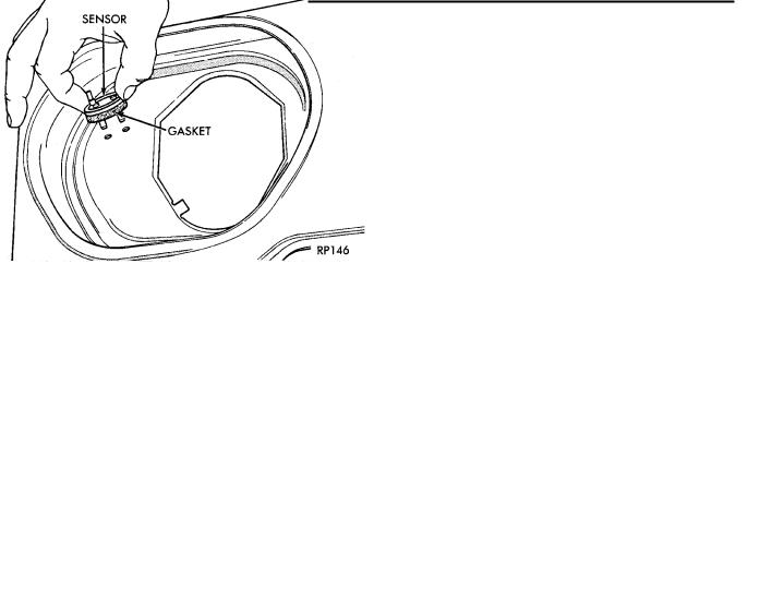
(1)Position gasket on the sensor. Install sensor (Fig. 5).
(2)While supporting the sensor on outer diameter, install new retainer clips securely. Ensure the gasket compresses to form an air seal. Do not attempt to adjust the sensor.
Ä
Fig. 4 Removing Sensor Clips
Fig. 5 Air Temperature Sensor Installation
HEATED OXYGEN SENSOR (O2 SENSOR)
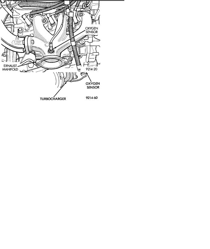
The O2 sensor threads into the exhaust manifold. It provides an input v oltage to the engine controller. The input tells the engine controller the oxygen content of the exhaust gas (Fig. 6, 7, 8, 9, or 10). The engine controller uses this information to fine tune the air-fuel ratio by adjusting injector pulse width.
The O2 sensor produces voltages from 0 to 1 volt, depending upon the oxygen content of the exhaust gas in the exhaust manifold. When a large amount of oxygen is present (caused by a lean air-fuel mixture), the sensor produces a low voltage. When there is a lesser amount of oxygen present (rich air-fuel mixture), the sensor produces a higher voltage. By monitoring the oxygen content and converting it to electrical voltage, the sensor acts as a rich-lean switch.
The oxygen sensor contains a heating element that keeps it at proper temperature during all operating modes. Maintaining correct sensor temperature at all times allows the system to enter into closed loop operation sooner and remain in closed loop during periods of extended idle.

Ä
Fig. 6 Oxygen SensorÐ2.5L Engine
Fig. 7 Oxygen SensorÐTurbo I Engine
In Closed Loop operation the engine controller monitors the O2 sensor input (along with other inputs) and adjusts the injector pulse width accordingly. During Open Loop operation the engine controller ignores the O2 sensor input. The controller adjusts injector pulse width based on preprogrammed (fixed) oxygen sensor input values and the current inputs from other sensors.
REMOVAL
CAUTION: Do not pull on the oxygen sensor wire when disconnecting the electrical connector.
EMISSION CONTROL SYSTEMS 25 - 17
Fig. 8 Oxygen SensorÐTurbo III Engine
Fig. 9 Oxygen SensorÐ3.0L Engine
Fig. 10 Oxygen SensorÐ3.3L/3.8L Engine
WARNING: THE EXHAUST MANIFOLD MAY BE EXTREMELY HOT. USE CARE WHEN SERVICING THE OXYGEN SENSOR.
(1) Disconnect oxygen sensor electrical connector.
