

Journal of Infrared, Millimeter, and Terahertz Waves
magnitude, dB
0 


-0.6 dB
-10
-20
-30 |
|
|
|
|S11|-simulation |
|
-40 |
|S21|-simulation |
|
|S11|-measurement |
||
|
||
|
|S21|-measurement |
|
|
Tolerance analysis (±10 m) |
|
-50 |
|
75 80 85 90 95 100 105 110
frequency, GHz
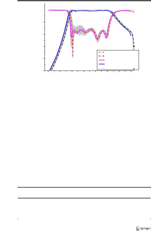
Fig. 5 Comparison between measured and simulated results of the proposed wideband W-band filter. (An effective conductivity of 3.5 × 10⁶ S/m is used in the simulations.) Tolerance analysis of the filter with ±1 0 μm in full W-band is also shown. (Boundaries of PEC are used in simulation)
construction of this proposed fifth-order waveguide filter based on the offset-coupling. Such linear and symmetrical architecture is composed by five cavity resonators. All the direct couplings between the arbitrary two adjacent resonators are magnetic couplings implemented by H-plane shifting windows. As can be seen in Fig. 3, an extra cavity is introduced in the input waveguide to generate a transmission zero by means of the extracted poles method [10]. Finally, such filter without any irises has a robust structure, which can be machined by CNC technology easily.
The performance of this filter is simulated and optimized by ANSYS HFSS, as shown in Fig. 5. Considering the situation of processing in practice, the corners in this filter model are filleted with a diameter of 0.5 mm. And the aluminum (Al) with effective conductivity of 3.5 × 10⁶ S/m [6] is used for the boundaries of the model during the simulation.
4 Measured Results and Discussion
This W-band waveguide filter is fabricated within an Al block by the classical CNC milling process. The minimum diameter of drills is 0.5 mm during the processing. The finished block
Table 1 comparison of performances among W-band waveguide filters
Reference [*] |
Center frequency |
Filter order |
No. of TZs |
3-dB FBW (%) |
Insertion |
Tech. |
||
|
(GHz) |
|
|
|
loss (dB) |
|
|
|
|
|
|
|
|
|
|
|
|
[1] |
93.7 |
4 |
0 |
4.9 |
1.3 |
DRIE |
||
[2] |
100 |
4 |
1 |
10 |
0.6 |
CNC |
||
[4] |
88.5 |
4 |
0 |
9.7 |
1 |
SU-8 |
||
[7] |
95 |
10 |
0 |
21 |
0.4 |
Electroforming |
||
This work |
92.5 |
5 |
1 |
20 |
0.6 |
CNC |
||
|
|
|
|
|
|
|
|
|
|
|
|
|
|
|
|
|
|

Journal of Infrared, Millimeter, and Terahertz Waves
has an overall dimensions of W × L × H = 20 mm × 20 mm × 20 mm, as shown in Fig. 4. The S-parameter performance in 75~110 GHz of this fabricated filter are carried out by using Agilent PNA-X VNA with FEV-10-TR W-band frequency extension modules after the through-reflect-line calibration.
Both the measured and simulated S-parameter responses of this wideband waveguide BPF are plotted together in Fig. 5 for comparison. It is obvious that the measurements are in good agreement with the simulations. The simulated results have a 3-dB FBW of 20% from 84.2 to 102.8 GHz, while the measured FBW is 20.2% from 83.6 to 102.3 GHz. There is a small frequency offset of about 0.5 GHz, which might be due to the processing tolerance between the expectation and practice. The measured insertion loss is only 0.6 dB and the return loss is better than 15 dB in the wide passband. From the comparison in Fig. 5, the transmission zero in the upper stopband can be inferred, which indicates that this BPF has a typical quasi-elliptic response.
In order to discuss the effects of the CNC milling process on filter performance, tolerance analysis has been carried out by using the method proposed in [11], as shown in Fig. 5. All dimensions of this W-band filter within ± 10-μm errors are simulated by HFSS. During the simulation, perfect conductor (PEC) is used for the boundaries of the model. As can be seen in Fig. 5, the performance of this wideband filter is not sensitive to machining errors (± 10 μm). The current CNC milling technology is a well-qualified machining technology for the fabrication of waveguide element at W-band.
A performance comparison between this proposed wideband waveguide BPF and some other similar reported ones operating at W-band is summarized in Table 1. It is clear that high performance of both wideband and low-loss is achieved for this BPF. The performance of the filter proposed in [7] is comparable with ours, but the tenth-order resonators and the narrow inductive irises cannot be fabricated easily, when operated at the higher frequencies especially.
5 Conclusion
Awideband and quasi-elliptical waveguide BPF has been developed at W-band based on the CNC milling technique. The wide FBW of 20% has been achieved by adopting the strong H-plane offset magnetic coupling in this linear fifth-order structure. Besides, an extra transmission zero in the out-of-band has been introduced by the extracted pole method. The measured results including a low insertion loss of 0.6 dB are very close to the simulated ones. It is worth mentioning that this robust, simple and high-performance waveguide BPF can be scaled to higher THz band likely. Effects of machining tolerance on filter performance also have been discussed to indicate the feasibility of CNC process for such wideband waveguide filter in W-band.
Funding This work was supported in part by the National Natural Science Foundation of China (grant no. 61671249 and no. 61801230) and the Startup Foundation for Introducing Talent of NUIST (no. 2018r018 and no. 2018r010).
Publisher’s Note Springer Nature remains neutral with regard to jurisdictional claims in published maps and institutional affiliations.

Journal of Infrared, Millimeter, and Terahertz Waves
References
1.S. Song, C. S. Yoo, and K. S. Seo, BW-band bandpass filter using micromachined air-waveguide resonator with current probes,^ IEEE Microw. Wireless Compon. Lett., vol. 20, no. 4, pp. 205–207, Apr. 2010.
2.C. A. Leal-Sevillano, J. R. Montejo-Garai, J. A. Ruiz-Cruz, and J. M. Rebollar, BLow-loss elliptical response filter at 100 GHz,^ IEEE Microw. Wireless Compon. Lett., vol. 22, no. 9, pp. 459–461, Sep. 2012.
3.X. Liao, L. Wan, Y. Yin, and Y. Zhang, BW-band low-loss bandpass filter using rectangular resonant cavities,^ IET Microw., Antennas Propag., vol. 8, no. 15, pp. 1440–1444, Jul. 2014.
4.X. Shang, M. Ke, Y. Wang, and M. J. Lancaster, BMicromachined W-band waveguide and filter with two embedded H-plane bends,^ IET Microw., Antennas Propag., vol. 5, no. 3, pp. 334–339, Feb. 2011.
5.Z.-C. Hao, W.-Q. Ding, and W. Hong, BDeveloping low-cost W-band SIW bandpass filters using the commercially available printed-circuit-board technology,^ IEEE Trans. Microw. Theory Techn., vol. 64, no. 6, pp. 1775–1786, Jun. 2016.
6.J. Ding, D. Liu, S. Shi, and W Wu, BW-band quasi-elliptical waveguide filter with cross-coupling and source–load coupling^, Electron. Lett., vol. 52, no. 23, pp. 1960–1961, Nov. 2016.
7.C. A. Leal-Sevillano, et al., BDevelopment of low loss waveguide filters for radio-astronomy applications,^ Infrared Physics & Tech., vol. 61, no. 11, pp. 224–229, 2013.
8.H. Wang, et al., BA design of 300 GHz waveguide bandpass filter with H-plane offset inductive window,^ in
IEEE 9th UK-Europe-China Workshop on Millimetre Waves and Terahertz Technologies (UCMMT), 2016, pp. 189–191.
9.J.-S. Hong and M. J. Lancaster, Microstrip Filters for RF/Microwave Applications. New York: Wiley, 2001.
10.C. A. Leal-Sevillano, et al., BA pseudo-elliptical response filter at W-band fabricated with thick SU-8 photoresist technology,^ IEEE Microw. Wireless Compon. Lett., vol. 22, no. 3, pp. 105–107, Mar. 2012.
11.J.-Q. Ding, S.-C. Shi, K. Zhou, et al., BAnalysis of 220-GHz low-loss quasi-elliptic waveguide bandpass filter,^ IEEE Microw. Wireless Compon. Lett., vol. 27, no. 7, pp. 648–650, Jul. 2017.