

Полезные материалы за все 6 курсов / Учебники, методички, pdf / INBDEBooster Orthodontics
.pdfORTHODONTICS
stimulation of cellular activity without interfering with blood flow to the area. There are different kinds of movements that can occur according to how force is distributed on the PDL.
• Bodily Movement
 Crown and root move in the same direction equally
 Ideal force = 100g
Load is applied to entire area of the PDL = equally distributed compression on one side of the root
• Uncontrolled Tipping
 Crown and root forced in opposite directions
 Ideal force = 50g (light force threshold)
50% of force is loaded on one side of the tooth, 50% on the other side
 Most pressure at the crest of alveolar bone and root apex
• Controlled Tipping
 Tooth partially tipped and partially translated
Root apex does not tip as much as uncontrolled tipping
 Ideal force = 75g
75% of force is loaded on one side of the tooth, 25% on the other side
• Extrusion
 Tooth being pulled out of its socket
 Ideal force = 50g
50% of PDL being loaded on any given side
 Irregularity of root shape causes compression in areas similar to tipping forces
•Intrusion
•Tooth being pushed into its socket
•Ideal force = 10g
•10% of PDL compressed
•Successful intrusion requires very light force along long axis of tooth
•Root Torque
 Root moves in direction of force, but crown barely moves
 Ideal uprighting force = 75g
  75% of PDL being loaded
21
• Rotation
 Tooth rotation along its long axis
 Ideal force = 50g
50% of PDL being loaded on any given side
 Irregularity of root shape causes compression in areas similar to tipping forces
Figure 1.05 Movement Types
INBDE Booster | Booster Prep™
ORTHODONTICS
2 Inflammatory Response
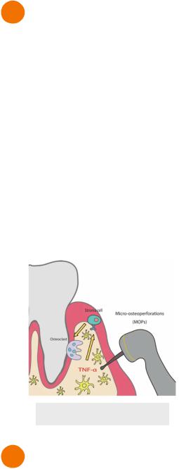
Regional Accelerated Phenomenon
•Method used to speed up tooth movement by utilizing the inflammatory response
•Regional - inflammation occurs at cut site and surrounding bone where tooth movement is aimed at
•Acceleratory - agitated inflammatory mediators intensify the bone response
•Tools used for regional accelerated phenomenon
 Propel - punches holes into the gums and bone
 Periodontal Accelerated Osteogenic Orthodontics - full thickness flap + alveolar corticotomies + bone flap + application of orthodontic force
Figure 2.01 Propel
3 Side Effects
Orthodontic forces can results in several deleterious side effects. Generally, more force is associated with more effects.
•Pain - PDL remodelling and necrosis
•Inflammation - can be exaggerated from poor oral hygiene or nickel allergy (rare)
•Mobility - PDL widened (temporarily)
•Pulp vitality loss - from extreme movements or tooth trauma
22
•Root resorption - cementum adjacent to hyalinized PDL can resorb
•Increased risk:
•Genetics
•Heavy force
•Large defect
•Apical defect
•Single rooted tooth
•Movement into cortical plate - leads to root resorption
•Tooth trauma
•Bruxism and heavy mastication forces
INBDE Booster | Booster Prep™
ORTHODONTICS |
23 |
MECHANICS OF TOOTH MOVEMENT
1 Mechanical Principles
Force
Force is a linear vector demonstrated with magnitude and direction.
•Orthodontics is made of push and pull force systems applied to teeth
•Force is applied to a location on the tooth (usually at the orthodontic bracket)
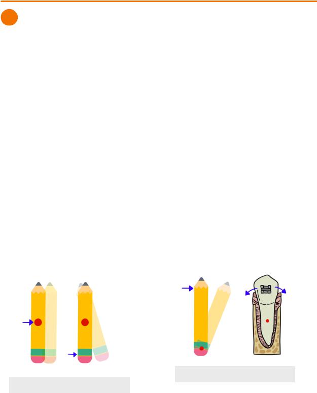
Center of Resistance
Center of resistance is fixed point where force must pass through for linear movement of an object.
•Center of resistance of free-floating object = object’s centre of mass
•If force is on the object, but not through the centre of resistance, the object may rotate  Example - pushing a pencil at the tip
•Center of resistance of tooth movement = centre of root
 Located on the centre of the portion of the root that is bound to bone
 If tooth has periodontal problems → center moves apically
 If there is root resorption → center moves occlusally
Moment of Force
Moment (MF) describes the tendency for a force to cause rotation at a specific axis on the object. It occurs whenever the force is applied at some distance from the center of resistance.
•Moment = Force x distance
 Similar to torque
•Rotation tendency is stronger the further the distance
 Example - closing a door is more difficult when pushing the door with the hands closer to the hinges than at the handle
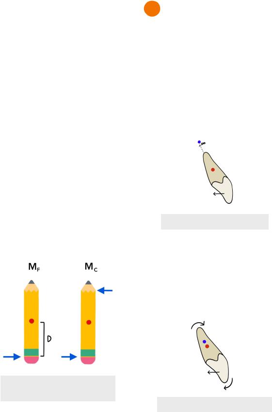
Center of Rotation
Center of rotation is an unfixed point that marks the axis through which an object is rotating. In other words, it’s the point where the object seems to have rotated between its original and final position.
•Example - pushing the pencil at the eraser and the center of the rotation is the tip
•In orthodontics, the force is applied at the bracket (crown), although the center of resistance is at the root
 Therefore, movement around the center of rotation is more common than at the center of resistance
Figure 1.02 Center of Rotation
Figure 1.01 Center of Resistance
INBDE Booster | Booster Prep™
ORTHODONTICS
Force Couple
Couple (Mc) occurs when there is application of equal and opposite non collinear forces (separated by some distance)
•Only rotational movement occurs
•Two points of contact required
•Orthodontic wires engaged into a bracket slot that has two points of contact with the tooth
•They way forces are applied to the bracket by the wire determines the kind of couple that influences the movement of teeth. The wire wants to return to its original shape resulting in forces applied to the bracket.
 First-order = rotation
 Pulling force on one contact point of the bracket, and pushing force at the other contact point
 Results in mesiodistal rotation of tooth
 Second-order = angulation
 Downward force on one contact point of the bracket, and upwards force on the other contact point
 Results in mesiodistal angulation of tooth
 Third-order - inclination
 Rectangular wired engaged in the bracket slot to cause buccal-lingual inclination of tooth
Figure 1.03 Moment of Force &
Couple
24
2 Tooth Movement
Bodily Movement (MC/MF=1)
•MC=MF, moment and force couples are equal
•Crown and root move equally in the same direction
•Tooth is translated (bodily), no rotation
 Center of rotation infinitely distant from the center of resistance
 Retraction, protraction, intrusion and extrusion
• Difficult movement to achieve
 Requires force to the crown and a strong couple
Figure 2.01 Bodily Movement
Uncontrolled Tipping (MC/MF=0)
• MC=0, no couples
 Lowest effort and easiest tooth movement
•Crown follows direction of force, root moves opposite to force
 Resulting from force coming from one point of contact
•Center of rotation slightly apical to the center of resistance
Figure 2.02 Uncontrolled Tipping
INBDE Booster | Booster Prep™
ORTHODONTICS
Controlled Tipping (0< MC/MF <1)
•MC<MF, moment of couple less than moment of force
•Crown tipping in the direction of force, but root remains fixed
 Seen in third-order couple
•Centre of rotation more apical to center of resistance
Figure 2.03 Controlled Tipping
Root Torque (MC/MF>1)
•MC>MF, moment of couple more than moment of force
•Root is moving more than the crown (crown barely moves) in the direction of force
•Center of rotation moves in opposite direction of root movement, located closer to incisal edge
•Very difficult movement to achieve
 Moving root through bone while keeping crown steady
 Very strong couple
 Likely requires auxiliary appliance
Figure 2.04 Root Torque
25
Rotation
•MF does not exist
•Only MC applied to the tooth
•Tooth rotates around its long axis
•Center of rotation located at the center of resistance
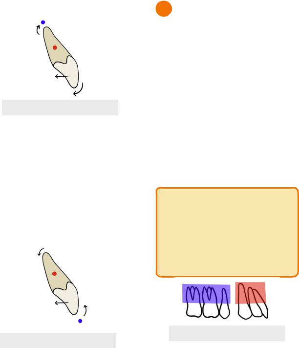
3 Anchorage
Anchorage in orthodontics refers to the tooth’s resistance to unwanted movement. As stated in Newton’s 3rd Law of motion, for every action there is an equal and opposite reaction. Therefore for every desired tooth movement, there is potential for an equally undesired tooth movement.
• Light force is preferred in orthodontics
 Has less anchorage toll/unwanted reaction movement.
•PDL surface area of teeth moving determines which movement dominates
 More PDL area = more anchorage to resist tooth movement
 Example - anterior teeth are less resistant to tooth movement compared to posterior teeth (more PDL surface area)
INBDE Pro-Tip:
Anchorage between teeth can resemble a game of “tug of war”. Whichever group of teeth has more PDL surface area can be seen as the stronger group and will resist movement more than the other group of teeth. This results in the weaker side experiencing overall net tooth movement.
Figure 3.01 PDL Surface Area
INBDE Booster | Booster Prep™
ORTHODONTICS |
26 |
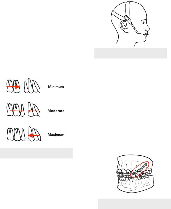
Anchorage after Premolar Extraction
In orthodontics, premolar extraction leaves space in the arch where the teeth were previously located. In this case, anchorage can be used to move the anterior or posterior teeth to close the gap.
2.Minimum anchorage
i.Anchor posterior teeth permitted to move forwards while non-anchor teeth remain fixed
ii.Often requires help from skeletal anchor or 2nd premolar extraction (not 1st)
3.Moderate anchorage
i.Anchor teeth can move 1/4-1/2 into the extraction space
4.Maximum anchorage
i.Often needed in severe crowding or incisor protrusion
ii.Anterior teeth pulled back and posterior teeth being anchored
iii.Anchor teeth should only move less than 1/4 into the extraction space
Figure 3.02 Anchorage Demand
Reciprocal Anchorage
•Both units have equal anchorage (PDL surface area is equal)
•Results in equal and opposite tooth movement in each unit
•Useful in diastema closure
Reinforced Anchorage
•Increase PDL surface area of anchor unit by including more teeth to the unit = increased anchorage
•Headgear often used to reinforced anchorage
 But often poor compliance
 Heavy intermittent forces due to putting on and taking off headgear are not ideal
Figure 3.03 Headgear
Skeletal Anchorage
•Uses temporary anchorage devices (TADs)
 Metal stakes that are screwed into bone that should not move and act like ankylosed teeth
 Bone screws - screwed into alveolar used to move individual teeth, less invasive than bone plates
 Bone plates - multiple screws attached to basal bone for extensive tooth movement, more stable than bone screws
 11 years is minimum age for TAD placement
 Bone mature enough to keep TADs stable
 Useful in moving molars distally or intruding molars
Figure 3.04 Bone Screw
INBDE Booster | Booster Prep™
ORTHODONTICS |
27 |
ORTHODONTIC MATERIALS
1 Wires
In orthodontics, braces are made up of a system of wires and brackets. The wires do all the work of dictating the movement of the tooth while the bracket just acts a handle for the tooth. The function of orthodontic wires can be summarized in four different stages.
1.Wire is out of the package untouched
2.Permanent bends placed in the wire to encourage tooth movement
3.Bend of wire is modified into order to engage into the bracket slot
i.Wire should experience resistance as it wants to return to its original shape
4.Overtime, wire returns to its original bended shape after the teeth have moved
Therefore, these four steps involve ongoing activation and deactivation of the wire in order to facilitate tooth movement.
•Activation/loading - force applied to the wire in order for it to be engaged into the bracket slot
•Deactivation/unloading - force applied to the tooth by the wire in order for the wire to return to its original shape
Stiffness
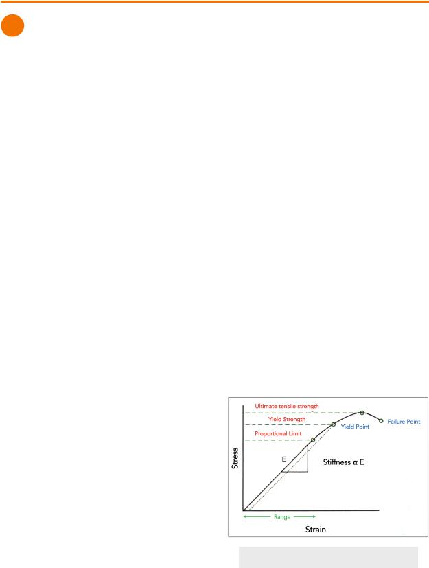
Stiffness is represented by the slope of the elastic portion of the stress-strain curve. The greater the slope, the more stiff the wire is.
Stiffness can also be explained by the following terms.
•Loading - refers to flexibility of the wire
•Unloading - refers to the amount of force that will be delivered to the tooth as the wire returns to original shape
•Stiffness and flexibility are the inverse of each other
Range
Outside of its range of action, a wire will not return back to its original shape. In orthodontics, a shorter range signifies that the patient will need to come back more often to replace their wire.
•Loading - how far the wire can be deflected while maintaining elasticity
•Unloading - how far and how long the wire will remain active
Strength
Strength of the wire can be explained by using the following terms:
•MPa - unit of stress used to measure strength
•Strength = Stiffness x Range
•Proportional limit - the point where any amount of stress beyond it will have not have the wire return to original shape
•Ideally, stress in orthodontics wires should be kept below this limit
•Yield Strength - the point where permanent deformation begins
•Ultimate tensile strength - maximum amount of stress and force the wire can experience
•Failure point - wire breaks
•Loading - refers to how easily wire can break
•Unloading - refers to amount of force the wire can deliver
Figure 1.01 Stress-Strain Curve
INBDE Booster | Booster Prep™
ORTHODONTICS |
28 |
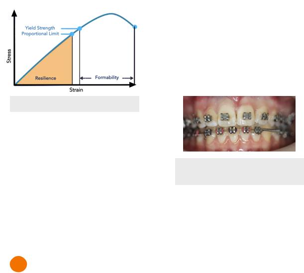
Resilience
In the stress-strain curve, resilience represents the area under the curve until the proportional limit.
• Refers to energy storage capacity of wire
Formability
In the stress-strain curve, formability represents the area under the curve from yield strength to failure point
•Refers to the amount of permanent deformation that will occur before failure
Figure 1.02 Resilience & Formability
Material
•Least to most stiff/strong
 NiTi < TMA < SS
Geometry
• Stronger and stiffer
 Rectangular > round
 Beam > cantilever
• ↑ diameter
 ↑ strength + stiffness
 ↓ range
• ↑ length
 ↓ strength + stiffness
  ↑ range
2 Brackets
Brackets are placed on the tooth for the wire to leverage on. There are several different types and classification of brackets;
Edgewise Brackets
Edgewise brackets have slots for the wire that open horizontally along the incisal edges of teeth. When the system was first invented, the same bracket was placed on each tooth. Therefore, the wire had to have a lot of bends for the wires to fit in each bracket.
•First-order bend - position teeth buccolingually
•Second-order bend - mesiodistal angulation
•Third-order bend - torque teeth in buccolingual inclination
Pre-adjusted Edgewise Brackets
Today, orthodontists use pre-adjusted edgewise brackets.
•Each bracket has its own design for different teeth
•Bends are already built into the bracket
•Not as many bends in the wire required
•Brackets placed in the centre of the facial side of the clinical crown of the tooth
Figure 2.01 Readjusted Edgewise
Brackets
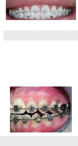
Metal vs Ceramic
• Metal
 Metal is visible, unesthetic
 Stainless steel material
 Wire held in place by elastic ring or stainless steel tie place over bracket slot
• Ceramic
 esthetic, similar colour to tooth
 More friction = harder for wire to slide through the bracket
 More prone to fracture
INBDE Booster | Booster Prep™
ORTHODONTICS |
29 |
Figure 2.02 Ceramic Brackets
Self-Ligating Brackets
•Built-in door the holds the wire into the slot
•No need for ligature/elastic ring/stainless steel tie
•More expensive
•Less friction
Figure 2.03 Self-Ligating Brackets
INBDE Booster | Booster Prep™
ORTHODONTICS
PHASE I TREATMENT
1 Phase I Treatment
Phase I treatment is regarded as early treatment that typically occurs during the mixed dentition stage before orthodontic treatment is given in phase II. There are three main purposes of phase I treatment in orthodontics.
1.Treat problems that are easier to correct earlier on
2.Improve overall oral environment
3.Make phase II treatment simpler in the permanent dentition
Crossbite
• Anterior Crossbite
 If on one to few teeth, can lead to uneven tooth wear and/or gingival strain
Treatment → 2x4 braces (2 molar bracket, 4 incisors brackets), active retainer
 Full underbite leads to skeletal class III
  Treatment → reverse pull headgear
Figure 1.01 2x4 braces
• Posterior Crossbite
 Usually due to a narrow maxilla
 Should be treated early if patient exhibits functional shift (mandible shifts as patient bite down), otherwise abnormal growth can be encouraged
 If no functional shift, can be treated later on
 Treatment
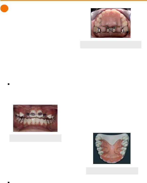
Palatal expansion (Haas, Hyrax, Quad Helix)
30
Figure 1.02 Hyrax Palatal Expander
Severe Overjet
•Increases risk for trauma
•Psychological and social problems could arise
•Treatment
•2x4 braces (2 molar bracket, 4 incisors brackets)
•Class II headgear - restrains maxillary growth at the sutures
Palatal Impingement
•Occurs when a deep bite causes lower incisors to impinge on the soft tissue of the palate
 Soft tissue trauma/damage to gingival attachment
 Leads to pain and discomfort
•Treatment → maxillary bite plate
 Protects the palate by restricting the deep bite
Figure 1.03 Bite Plate
INBDE Booster | Booster Prep™