

and the web browser host strips the received message to pass to the application layer supporting the web browser.
Packaging (Beyond Paper or Plastic)
At a very granular level, data exchanged between hosts must be bundled in some kind of standard format. A host is a generic term that can reference a workstation on your desk, a router, or a web server to name just a few examples. The important distinction is that these computers are connected to a network capable of transporting data to and from the computer. In the generic sense, the packaging of associated data is called a packet. The problem in terminology arises because this data package is labeled differently at various layers of communication between the source application and the destination application located on different hosts. This section discusses some of the key concepts related to data packaging,
including bits, bytes, packets, data encapsulation, and interpretation of the layers.
Bits, Bytes, and Packets
The atom of computing is a bit, a single storage location that has a value of either 0 or 1 (also known as binary). Although succinct and compact, you cannot actually store or convey a lot of information with a single bit, so bits are grouped into clumps of eight. A unit of eight bits is a byte (or octet, if you prefer). Eight times a very small amount of information is still pretty small, but an octet can contain an American Standard Code for Information Interchange (ASCII) character, such as the letter a or a comma (,). It can also hold a large integer
number, as high as 255 (28-1).
Bits, Bytes, and Binary
Figure 1.2 shows a byte. Because this discussion is focusing on bits, binary is the language used— the language of 0s and 1s. Each bit is represented as a power of 2, the base of binary. Notice that a byte spans powers of 2 from 20 through 27. If all bits have a value of 0, the byte is obviously 0. Now, imagine that all bits are 1s. Add up all the individual bit values, starting with the smallest value (20 = 1, any base with an exponent of 0 is 1); you will have 1 + 2 + 4 + 8 + 16 + 32 + 64 + 128. The total value is 255, and that is the maximum value that a given byte can have. This value is examined later when the discussion turns to IP addresses.
Figure 1.2.
You just saw an example of how binary-to-decimal conversion is done. If you are given a byte of data, just re-create this byte with the appropriate powers of 2 and their associated decimal values. Any bit that is set is assigned the accompanying decimal value of that bit. Then, just total up all the decimal values; voila, the conversion is done. This is not really rocket science after all.
Multiple bytes, or octets, are grouped together for shipping across a network by packaging
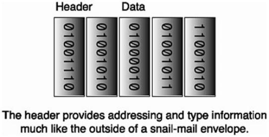
them into packets. Figure 1.3 shows one of the great truths of networking: An overhead cost accrues when slinging packets around the network.You have to go through a lot of trouble to package your content for shipping across a network and then to unwrap it when it gets to the other side (and even more trouble, of course, to finish the job with a tamper-proof seal). A field known as the cyclical redundancy check (CRC), or checksum, is used to validate that the frame (the name given to the packet on the wire) has not been damaged or corrupted in transit.
Figure 1.3. Portrait of a packet.
Like an envelope addressed for mailing, IP packets need to include the addresses of both the sending and receiving hosts (see Figure 1.3). If you live in a house with a street address, you can think of that as your hardware address, the address assigned to your house. In networking, at least with Ethernet networks, this is analogous to a network interface card's (NIC) Media Access Controller (MAC) address. This hardware address is assigned to the NIC when the card is constructed. The MAC address is 48 bits long, which means it can hold a very large number (248-1). The "Addresses" section later in this chapter discusses the differences between MAC addresses and IP addresses.
To create a frame, which is the name the packet acquires when transmitted on physical media, you construct the packet using various protocol layers and then include the physical information. Finally, the frame is placed on the networking medium by the NIC. The frame has a frame header of 14 bytes, with fields such as the source and destination MAC addresses,
frame data that can vary in length, and a trailer of 4 bytes that represents the CRC.
Encapsulation Revisited
Figure 1.4 represents the concept of the layered packaging configuration. Different layers of protocols theoretically "talk" to like layers of protocols on the source and destination hosts. The layers are stacked atop one another— hence, the origin of the term "TCP/IP stack." At each layer of the stack, the packet consists of a header of its own and data, sometimes known as the payload. All the encapsulation is done for the purpose of sending some kind of content, but the encapsulation requires different header information at different levels in its journey from source to destination.
Figure 1.4. One layer's header is another layer's data.
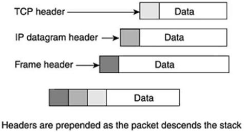
Suppose that you have a message or other content to send. It is first collected by the application, which could be a program such as telnet or electronic mail; these TCP applications are discussed in more detail in the section "IP Protocols." The TCP packet is known as a TCP segment and includes the TCP header and TCP data. If this were UDP, the packet would be known as a datagram, which is confusing because it is redundant with the name at the IP layer.
At this point, the TCP segment is handed down from the TCP layer of the TCP/IP stack to the IP layer. The IP layer prepends (that means appends at the front) header information to the TCP segment and becomes known as an IP datagram. Really, the TCP header and data become invisibly enmeshed as data for the IP datagram, which has its own header. The IP datagram is delivered to the link layer of the TCP/IP stack, and it is known as a frame. The link layer prepends the frame header to the IP datagram to carry it across the physical medium, such as Ethernet.
The process is repeated in reverse when the frame arrives at the destination host and all headers are stripped away and passed to the proper upper-layer protocols. Each layer of the TCP/IP stack with its embedded message converses with the similar layer of the receiving
host.
Interpretation of the Layers
With all the layering going on, the bottom line is that you have a bunch of adjacent 0s and 1s. How do you know how to interpret them? Suppose that you are looking at the IP header; how do you know what kind of embedded protocol you will find following it? Surely that must be known to properly interpret the protocol. The term protocol is meant to denote a set of agreed upon rules or formats. Each protocol (such as IP, TCP, UDP, and ICMP) has its own layouts and formats.
Figure 1.5 shows an example of the organization of the IP header. You can see that a certain number of bits are allocated for each field in the header. A Protocol field identifies the embedded protocol. Each row that you see in the IP header is 32 bits (0 through 31, inclusive), which means four (8-bit) bytes. To complicate matters a little, counting starts with 0 when talking about bit and byte locations. The first row represents bytes 0 through 3; the second row represents bytes 4 through 7; and the third row represents bytes 8 through 11. Notice that the circled Protocol field is in the third row. The preceding time-to-live (TTL) field is 1 byte long, which makes it the 8th byte; and the Protocol field, which is also 1 byte long, represents the 9th byte. This means that the 9th byte (actually, it's the 10th byte, but remember counting starts at 0) is examined to find the embedded protocol. The point is that most packets at their respective levels are positional; fields can be discovered by going to known displacements in the packet.
Figure 1.5. Positional layouts.