

interface and marking packets that might otherwise have been dropped as experiencing congestion.
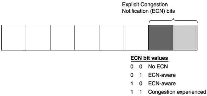
There are two possible values of the ECN bits to inform that the sending host is ECN-capable. The ECN-capable Transport (ECT) bit settings can either be 01 or 10 in these two low-order bits of the differentiated services byte in Figure 8.3. These settings indicate that the sender is ECNaware. If the sender is ECN-aware, a router that uses RED attempts not to drop the packet, but instead sends it with the Congestion Experienced (CE) bits enabled, and the receiver reacts to this. The bit setting for Congestion Experienced is 1s in both of the ECN bits. We'll discuss the receiver's response in more detail when we cover the TCP fields in the next chapter.
Figure 8.3. The Differentiated Services byte and ECN.
The Don't Fragment (DF) Flag
The Don't Fragment (DF) flag is a field in the IP header that is set when fragmentation is not to occur. If a router discovers that a packet needs to be fragmented, but the DF flag is set, the packet is dropped and an ICMP message "unreachable - need to frag (MTU size)" is delivered to the sending host. Most current routers include the maximum transmission unit (MTU) size of the smaller link that required the fragmentation.
Fragmentation comes with some overhead, so you should avoid it altogether. If one fragment of the fragment train is not delivered, all fragments must be re-sent. Because of this, when some TCP/IP stacks send data, they first send a discovery packet with the DF flag set. If the packet goes from source to destination without any ICMP errors, the selected datagram size of the discovery packet is used for subsequent packets. If an ICMP message is returned with an "unreachable error – need to frag" message and the MTU is included, the packet is resized so that fragmentation does not occur. This assumes the site allows these ICMP messages inbound. Some operating system TCP/IP stacks set the DF flag on certain types of packets, and nmap uses this as one of the tests to try to fingerprint the operating system. Also, an attacker can use the DF flag as a means of an insertion attack. This means the NIDS would have to be on a network with a larger MTU than the final destination host. In this case, one or more packets among a series of others have the DF flag set. The NIDS receives the packet(s) and accepts it, but the end host never receives the packet(s) because fragmentation is required, yet the DF flag was set.
The More Fragments (MF) Flag
The More Fragments (MF) flag tells you that one or more fragments follow the current one. All fragments except the final one should have the MF flag set. The way that a receiving host detects fragmentation is that this flag is set or the fragment offset field in the IP header is set
to a non-zero value.
Mapping Using Incomplete Fragments
Another mapping technique is to try to elicit an ICMP IP "reassembly time exceeded" message from hosts on a scanned network. This can be done by sending an incomplete set of fragments to hosts that are being mapped. For this to work properly, the destination host has to be listening on the port that is scanned if the traffic is TCP or UDP. When the scanned host receives the first fragment, it sets a timer. If the timer expires and the receiving host has not received all the fragments, it sends the ICMP "IP reassembly time exceeded" error back to the sending host.
It is important to note (according to RFC 792) that for the ICMP "IP reassembly time exceeded" error to be generated, the first fragment must not be the missing one. If no first fragment is received, the host receiving the fragments never sets the timer. RFC 1122 recommends that the
timer expire between 60 seconds and 2 minutes, though we'll see that is not always the case. hping2 –S –p 139 –x win98
06:49:36.986218 verbo.2509 > win98.netbios-ssn: S 1980004944:1980004944(0) win 512 (frag 38912:20@0+)
06:50:41.636506 win98 > verbo: icmp: ip reassembly time exceeded
hping2 –S –p 21 –x linux
11:56:04.064978 verbo.2450 > linux.ftp: S 1198423806:1198423806(0) win 512 (frag 39067:20@0+)
11:56:34.056813 linux > verbo: icmp: ip reassembly time exceeded [tos 0xc0]
Hping2 is freeware that is used to generate different types of traffic. Hping2 is first executed with the –S option to send a packet with a SYN, a destination port of 139, -p 139, and the –x option to set the More Fragment flag. One packet is sent to the destination host win98, which as you might guess is a Windows 98 host listening on TCP port 139.
The fragment sent is actually the entire SYN packet—20 header bytes and a 20-byte TCP header. There is no data to send, but the receiving host has no way of knowing this because the MF flag is set. You can see that the MF flag is set by looking at the + in the previous output of TCPdump. The Windows host took approximately one minute and five seconds to time out the fragment reassembly clock. That is when you see the ICMP "IP reassembly time exceeded" message returned.
The next hping2 test is tried on a Linux (2.2 kernel) host on a listening ftp port. The Linux host
took about thirty seconds to time out on incomplete fragments sent to destination port 21.
IP Numbers
IP numbers are 32-bit fields. The source IP number is located in the 12th through 15th bytes offset of the IP header; the destination IP number is located in the 16th through 19th bytes offset of the IP header.
What are some unnatural values for source IPs entering your network? If you see an IP number entering your network that purports to be from your network, there is a problem. Most likely, someone has crafted this packet and is spoofing an IP address in your range. A packet-filtering device should shun this traffic. Additionally, you should never see source IPs coming from the loopback address 127.0.0.1, nor should you see any source IPs that fall in the Internet Assigned Numbers Authority (IANA) reserved private network numbers defined in RFC 1918. These
address ranges can be found at www.iana.org/assignments/ipv4-address-space. Their intended use is for local internal networks only.
As far as traffic leaving your network, it should have a source IP number that reflects your network's address space. If you see an IP number coming from inside your network that has an IP number of a different address space, it is either being spoofed or there is a misconfiguration problem with a host inside your network. In either case, this traffic should not be allowed to leave your network. This prevents hosts in your network from participating in distributed denial of service attacks because participant or zombie hosts usually use spoofed source IP numbers so that they cannot be located. Other types of scans use decoy or spoofed source IP's as a smokescreen. By disallowing outbound traffic that is not part of your address space, these scans will be ineffective as well.
You should also never see a source IP with the loopback 127.0.0.1 address leaving your network because that identifies the local host. And, you should never allow source IP's in the reserved address ranges to leave your network.
Finally, you shouldn't allow traffic with a broadcast destination IP address into or out of your network. Such destination addresses are typically used to quickly map other networks or use
them as Smurf amplification sites.
IP Identification Number
The IP identification value is found in bytes 4 and 5 offset of the IP header. For each new datagram that a host sends, it must generate a unique IP ID number. This value is normally incremented by 1, although some use an increment of 256, for each new datagram sent by the host.
This unique value is required in case the datagram becomes fragmented. All fragments from the datagram share this same IP ID number. This is also referred to as the fragment ID number. It is the number that is used by the receiving host to reassemble all fragments associated with a common datagram.
The range for IP ID values is 1 through 65,535 because this is a 16-bit field. Usually, you don't see IP ID numbers with a value of 0. When the maximum value of 65,535 for the IP ID value is reached, it should wrap around and start again. Different source IPs directing traffic to your network should manifest a different chronology of IP ID values. So, if you see different "alleged" source IPs sending traffic to your network and they appear to have a chronology of incrementing IP ID numbers, it is possible that the source IPs are being spoofed.
As with just about any other field or value in the IP datagram, this value can be "crafted" so as to render it meaningless for interpretation. For instance, if an attacker used a tool that sent all packets with the identical IP ID, they would offer no meaningful forensic value about the attacker's host. The –vv option of TCPdump can be used to display the IP ID number along with
the time-to-live (TTL) value.
Time to Live (TTL)
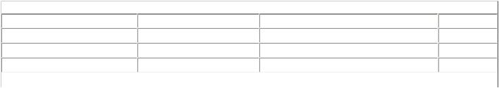
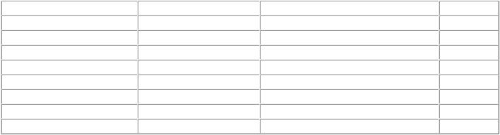
The TTL is an 8-bit value that is set by the host sending the datagram. Initial TTL values are different depending on the TCP/IP stack used, as you can see in Table 8.1 that was obtained at project.honeynet.org/papers/finger/traces. As we have discussed, each router that
the packet travels on its way to the destination host must decrement the TTL value by 1. If a router ever discovers a value of 0 in the TTL, it must discard the packet and return an ICMP "time exceeded in-transit" message back to the sender. This banishes lost packets such as those stuck in a routing loop. This can be used as a possible insertion attack if the NIDS sees the packet, yet the TTL is low enough to be expired by a router before it reaches a target host.
|
Table 8.1. Initial TTL Values by Operating System |
|
|
OS |
Version |
Platform |
TTL |
Windows |
9x/NT |
Intel |
32 |
AIX |
4.3.x |
IBM/RS6000 |
60 |
AIX |
4.2.x |
IBM/RS6000 |
60 |
Cisco |
11.2 |
7507 |
60 |
IRIX |
6.x |
SGI |
60 |
Linux |
2.2.x |
Intel |
64 |
OpenBSD |
2.x |
Intel |
64 |
Solaris |
8 |
Intel/Sparc |
64 |
Windows |
9x/NT |
Intel |
128 |
Windows |
2000 |
Intel |
128 |
Cisco |
12.0 |
2514 |
255 |
Solaris |
2.x |
Intel/Sparc |
255 |
What if you want to test to see if a packet is from the source IP it says it is from? You can look at the arriving TTL, estimate the initial TTL by using Table 8.1, and subtract the arriving TTL from the initial TTL to give you the hop count for the packet to arrive on your network. Then, a traceroute could be executed to see if the number of hops taken back to the alleged source IP approximates the number of hops originally taken into your network. It is possible that the route back to the alleged source IP might be different than the route taken to your network because of the dynamics of routing, but they often do have close hop counts, assuming that there are no major router or traffic problems along the way.
Chances are, if you have different source IPs concurrently entering your network, they have different arriving TTL values. If you see different source IPs entering your network at the same time, doing the same type of activity, with identical arriving TTLs, it is possible that this might be source IP spoofing.
Be aware that some scanning programs purposely randomize the initial TTL value just to eliminate this vestige of the true origin of the datagram.
Looking at the IP ID and TTL Values Together to Discover Spoofing
Examine the following output:
07:31:57.250000 somewhere.de > 192.168.104.255: icmp: echo request (ttl 246, id 5134)
07:34:18.090000 somewhere.jp > 192.168.104.255: icmp: echo request (ttl 246, id 5137)
07:35:19.450000 somewhere.ca > 192.168.104.255: icmp: echo request (ttl 246, id 5141)
This output shows traffic from three purportedly different source IPs to the same infrequently referenced destination IP. The timestamps are within minutes of each other, and the chronology of the IP identification values is worth examining. What is strange about the IP identification values, and why might someone send traffic such as this?
What are the odds that the IP identification values are coincidentally incremental from three alleged different sources to the same destination IP— 192.168.104.255? The particular subnet 192.168.104 does not have active hosts, so this makes the traffic even more suspicious. Although this could be a huge coincidence, it is more likely that someone on one host was sending ICMP echo requests (ping) to the infrequently referenced internal 192.168.104.255 address.
Recall that the IP identification value is a 16-bit field with a range of values from 1 to 65,535. The clustering of values between 5134 and 5141 is highly unlikely for three unique sources. It also appears to be a particularly inactive host (perhaps a single user PC) sending the packets, judging by the small increments in the IP identification values over several minutes. This assumes that the IP identification numbers have not been crafted.
As with much unusual traffic seen on the network, the what is far easier to figure out than the why. Maybe this was a mapping attempt with one real source and two spoofed sources. This emits a smokescreen effect; even if we noticed this, chances are we wouldn't be able to identify the real source IP anyway.
Let's examine this same traffic, but now let's look at it in terms of the TTL values. Oddly, all the arriving TTL values are identical. This tends to confirm the speculation that all three packets