

VLE 3 Wave optics
.pdfGeneral
There is Fresneland Fraunhofer-diffraction.
Fresnel-diffraction = near field-diffraction Fraunhofer-diffraction = far field-diffraction
Setup for explanation: In distance R1 to a untransparent object with a small aperture there is a point source. The aperture has the diameter a. In the distance R2 to the opening a screen is placed.
Source
Aperture
Screen
61
Prof. M. Schmidt
Institute of Photonic Technologies, Univ. Erlangen, Germany

Fesneland Fraunhofer-diffraction (1)
Assumption: The point source has infinite → plane waves at the aperture observation plane is directly behind the aperture (R1 >> a, R2 → 0)
→ Clear image of the aperture
Increase of distance between aperture and screen (R2 > 0)
→Image of the aperture visible, but superimposed with structures
→Fresnel-diffraction
Further increase of R2
→Increase of the interference fringes, no similarity to the aperture anymore Further increase of R2
→Only increase of the
interference fringes
→ Fraunhofer-diffraction
62
Prof. M. Schmidt
Institute of Photonic Technologies, Univ. Erlangen, Germany

Fesneland Fraunhofer-diffraction (2)
A sufficient reduction of the wavelength would lead to Fresnel-diffraction. → Wavelength of 0 is geometrical imaging
With decrease of R1 spherical waves hit the aperture. → Fresnel-pattern stays also with big R2
Summary:
Fraunhofer-diffraction will be generated, if the waves hitting the aperture are nearly plane within the size of the aperture (or obstacle).
Is this it not true and the waves are not plane (e.g. close point source) Fresneldiffraction is caused. Fresnel-diffraction is also generated if the observation plane is close to the aperture.
Rule of thumb: Fraunhofer-diffraction is generated if:
R a2 
R – smaller of the distances between source and aperture or aperture and observation plane
a – diameter of the aperture
63
Prof. M. Schmidt
Institute of Photonic Technologies, Univ. Erlangen, Germany
Fraunhofer-diffraction
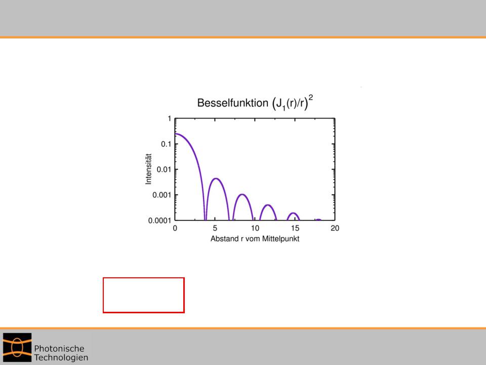
Diffraction at a circular aperture:
→ The diffraction pattern of Fraunhofer-diffraction can be described with a Bessel-function (Airy function):
|
|
|
source: http://de.wikipedia.org |
|
The central maxima is called the “Airy-disc” |
||||
calculation: |
|
R |
|
|
r |
1.22 |
R – distance from aperture to observation plane |
||
|
||||
Airy |
D |
D – diameter of the aperture |
||
|
|
|||
64
Prof. M. Schmidt
Institute of Photonic Technologies, Univ. Erlangen, Germany

Image of interference pattern (fringes)
Interference fringe
 1. Order
2. Order …
source: http://de.wikipedia.org
Airy-disc
65
Prof. M. Schmidt
Institute of Photonic Technologies, Univ. Erlangen, Germany
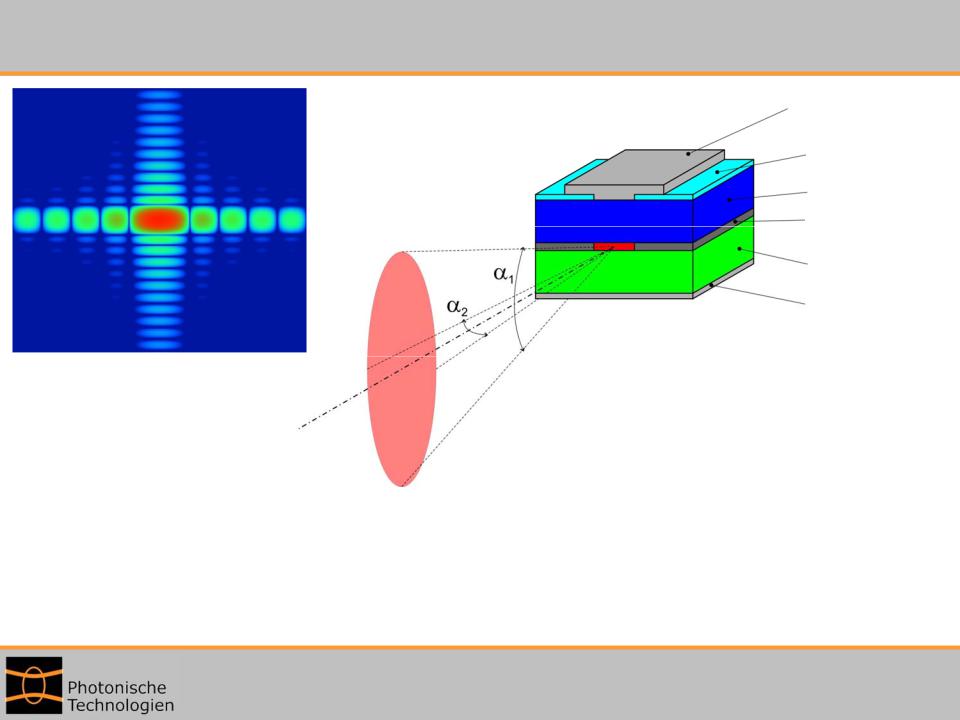
Diffracted beam from a laser diode
Electrode
Cover glass
p-substrate pn-junction
n-substrate
Electrode
Fresnel-interference patter close to the aperture
The elliptic beam characteristic is cause by Fraunhofer diffraction. „fast axis“ ( 1): 30° - 40 °
„slow axis“ ( 2): 12° - 15°
→ Collimation with cylinder lens.
66
Prof. M. Schmidt
Institute of Photonic Technologies, Univ. Erlangen, Germany
Fresnel-diffraction (1)
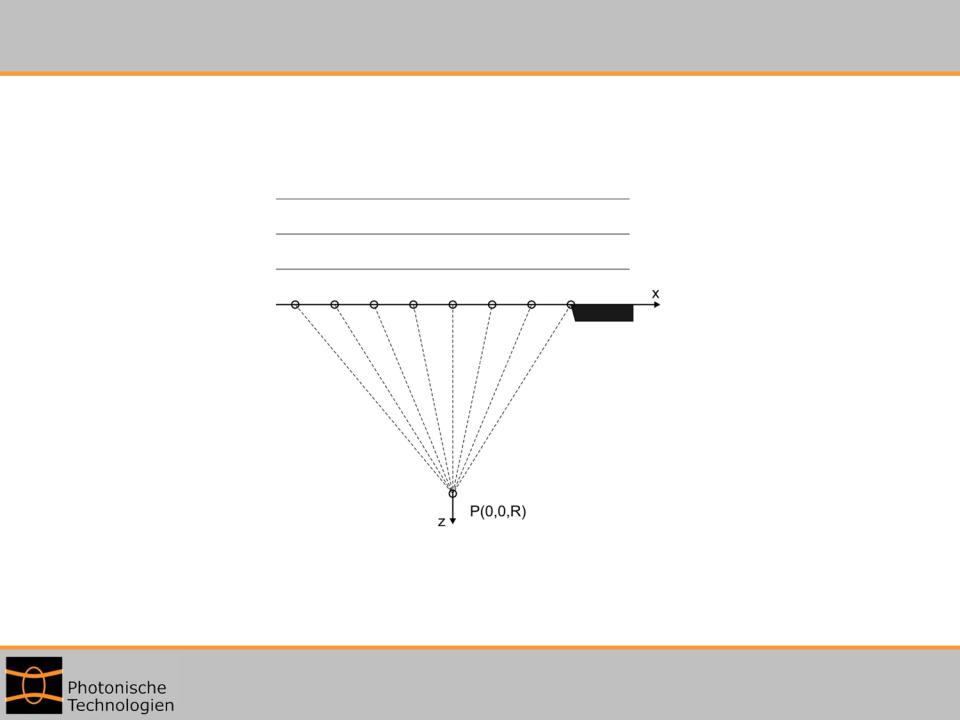
→ The interference pattern with Fresnel diffraction is described with fresnel-zones. assumption: A plane wave is hitting a absorbing half plane
Incident plane wave
Object
Observation point
The diffraction plane is at z = 0
With the Huygens principle you sum up the secondary waves in the observation point P(0,0,R)
67
Prof. M. Schmidt
Institute of Photonic Technologies, Univ. Erlangen, Germany
Fresnel-diffraction (2)
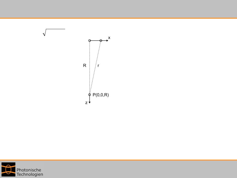
The way r of the secondary waves from point x to the observation point P changes with x:
r |
x2 R2 |
|
For x = 0 → r = R |
z = 0 |
|
r is increasing slowly with increasing x.
For r < R+ /4 This areas are constructive to the field at point P from x=0. For R+ /4 < r < R+3 /4 it is negative.
→ has to be subtracted at P from the signal
For R+3 /4 < r < R+5 /4 it is positive again, ...
68
Prof. M. Schmidt
Institute of Photonic Technologies, Univ. Erlangen, Germany
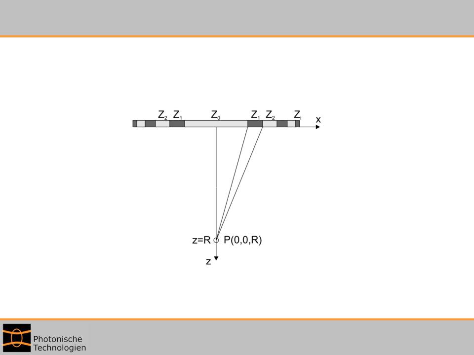
Fresnel-Zones (1)
Aperture areas with the same sign are called Fresnel-Zones
+- + - …
R+ /4
R+3 /4
69
Prof. M. Schmidt
Institute of Photonic Technologies, Univ. Erlangen, Germany
Fresnel-Zones (2)
For small |x| these zones are big.
For rising |x| they become smaller and more similar to each other
→Parts from neighbouring zones cancel each other
→The diffracted field at P is described nearly completely from Fresnel-Zones with low number
Hence there is a possibility to gain a higher intensity in the centre of the diffraction pattern
→ Focusing effect
The realisation is done with a Fresnel-zone plate:
Focal length is set for specific wavelength → Strong chromatic aberrations
Usage with e.g. X-rays, because there are no materials with matching refractive index.
70
Prof. M. Schmidt
Institute of Photonic Technologies, Univ. Erlangen, Germany