

книги / Innovative power engineering
..pdfa electrical power generating system by using the piezoelectric ceramic as the electricity generating part and put it under the rail. When the subway pass through the certain part of the rail, piezoelectric ceramics which are asserted under each sleeper would be compressed continually, then the electric current would pass through the circuits which can make the current more steadily, and finally being collected by electronic or being used by the car of the subway directly. Using this electronic system, we can truly achieve the objective of the energy saving.
Fig. 11. The subway rail
However, because of the tremendous weight of the subway, we have not found a proper way to protect the piezoelectric plates from undertaking such great pressure, so that the pressure might damage the plates. If this problem can be solved, this system can install under the subway rail and bring tremendous electricity.
5.Innovation points
1)Piezoelectric ceramics are very cheap but can generate big amount of electricity, by using this material, we can achieve the objective of low cost and high-efficiency.
2)There is no need for worker to operate it, the electricity can be collected by battery automatic when the vehicle passing through the strip.
311
3) Nowadays, the using of road deceleration strips are very common, thus, if this system can be achieved successfully, it can be applied on different places and collect the energy that used to be wasted.
References
1. |
|
. |
. |
|
. – 1979. – Vol. 2–26. |
2. |
|
. |
. |
|
. – 1983. |
3. |
. |
, |
. |
. |
. – 1973. – |
Vol. 2–8. – P. 205–225. |
|
|
|
|
|
4. |
|
|
. |
|
. |
|
|
. – 1998. – Vol. 6[5]. |
|
|
|
5. |
|
|
|
|
. |
|
|
. |
25 |
|
4 . – 2006. – Vol. 8. |
6. |
. |
|
. |
|
. – 2011. |
7.Holler, F. James; Skoog, Douglas A; Crouch, Stanley R (2007). “Chapter 1”. Principles of Instrumental Analysis (6th ed.). Cengage Learning. – 2007. – P. 9.
8.Harper, Douglas. ”piezoelectric”. Online Etymology Dictionary.
9.Manbachi A., Cobbold R.S.C. Development and Application of Piezoelectric Materials for Ultrasound Generation and Detection // Ultrasound. – 2011. – Vol. 19 (4). – P. 187–196. DOI:10.1258/ult.2011.011027.
10.Gautschi G. Piezoelectric Sensorics: Force, Strain, Pressure, Acceleration and Acoustic Emission Sensors // Materials and Amplifiers. Springer. – 2002.
312
ARRAY FLOAT BOWLS STORM PROOF WAVE ENERGY CONVERSION SYSTEM USED IN ISLAND
Xu Yifan, Huang Siqi
Southeast University
Ocean resources are rich around islands.A solution to the energy problem for islands is needed. Most existing energy systems using wave energy have many shortcomings like large space required, weak ability of wave/wind resistance,etc.They are not suitable for island.This work is a new array-type storm proof wave energy generation device which is designed as a medium-and-small-sized energy system for island.The equipment consisted of many floats and energy generation device.The vane is placed on the float. Between the float and the energy generation device is a transmission cable. When the wave rises from trough to peak, the float goes up and pulls up the cable; meanwhile, water dashes the vane and the vane furls the cable through the roller. It uses the rope to drive the generator.The rest energy used to reset keeps in the torsion spring which is in the end of the cable. When the wave travels from peak to trough, the energy saved in the torsion spring will retract the cable and wait for the next cycle.Contrary to existing wave energy equipment,this device has following features:
1)It breaks one single device into many smaller floats,which will improve the ability of wave/wind resistance and avoid the hogging.
2)Several cells work in different phase. They will complement each other and improve the generating quality.
3)It does not need land surface which will be more appropriate for island. And its modular structure will be more convenient for installation and maintenance.
Keywords: wave power generation float-type array-type distribution wave/wind resistance.
1.Background
There is a vast ocean area and large amounts of ocean energy resources in our country, especially in the South China Sea. Clustered around the South China Sea are mostly islands. Compared with the ocean,land area of islands is so small that it is too difficult to produce electricity on the island.And because of the disputes in the South China Sea,China is speeding up its development in some islands.But those islands are far away from the land and is lack of energy supply.To achieve our country’s sustainable development of those islands economically and militarily, we must adjust measures to local
313
conditions. We should make the most of ocean energy and reduce our dependence on fueling [1].
Using the ocean wave power is the main way of ocean wave energy utilization.It can provide clean power for outlying islands and offshore installations.The Oscillating Water Column (OWC) wave power device is more developed methods to use the wave power.But it is costly to build a dam.And it needs large land area unit power [2]. There are also nodding duck and Pelamis.These ways will suffer greater pressures when faced with the huge waves.Their device security is poor. In general, most existing energy devices are large single structures.They are complicated and poor in wave/wind resistance and have many other defects [3].
This work is based on medium-and-small-sized independent energy system for island and puts forth a new low and medium power offshore wave energy generation.It absorbs potential energy through the the array floats.The impeller of the float absorbs the kinetic energy.And steel-rope drives the motor to generate.These ways are more advanced and feasible and can improve the shortcomings of existing devices.
2. Designing Scheme
2.1. Overall Structure and Layout
Basic working of this work is absorbing potential energy through the array floats; the impeller of the float absorbs the kinetic energy and steel-rope drive the motor to generate. The basic structure of the device is shown in Fig. 1.
The device is installed offshore from land 500~1000 metres. The caisson is installed on sea bottom and the floats float on the sea. The float is connected to the steel-rope and adjusts it. Based on the actual situation of the wave and the sea, it needs several floats. Each float has a corresponding caisson which can drive the generator through the transmission. Meanwhile, the vane furls the cable through the roller to drive the generator.
314

Fig. 1. The basic structure diagram
2.2. Work Process
When the wave travels from trough to peak, the float goes up and pull up the cable; meanwhile, water dashes the vane and the vane furls the cable through the roller. It uses the rope to drive the generator. The rest energy used to reset keeps in the torsion spring which is in the end of the cable. When wave travels from peak to trough, the energy saved in the torsion spring will retract the cable and wait for the next cycle.The work process of the device is shown in Fig. 2.
Fig. 2. Process flow diagram
315

2.3. Structure of Each Part and functions
According to the above described overall structure and layout, we built a physical model as shown in Fig. 3. And then we will introduce the structure of each part and function through the model.
Fig. 3. Unit cell model structure chart
Float System
As is shown in Fig. 3, the float is a box structure. It can float on the water and will not sink under certain pulling force. The float is made by low density material or made hollow. The vane will be installed on the reverse side of the float and the side that faces the sea. When the wave comes, water dashes the vane and the vane furls the cable through the roller. And the float will roll up the cable with buoyancy either.
Transmission and Generating System
Transmission and generating system include transmission ropes, adapting piece, pulley in the middle, transmission pulley, torsion reel and generator. Fig. 4 is transmission and generating system.
Transmission rope is splited into two sections, and is made from different materials. Rope 1 is linked to the float. Rope 2 is linked to
316
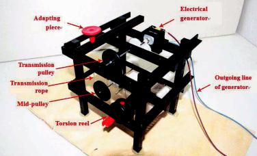
torsion reel and two pulleys. These two ropes link up in adapting piece. Rope 1 is exposed directly to sea water. Its working environment is bad. So it is made from tensile corrosion resistant material. Rope 2 is placed in the box in the bottom as transmission rope. Choice of corresponding rope is based on the transmission pulley’s type. Because rope 2 works in a good environment and need not to be long, good quality rope will do.
Adapting piece is a structure that connects two ropes and perfoms a sealing function. Rope and adapting piece do not move. When the rope is moving up and down, it contacts the outside box with the adapting piece. The outside surface of the adapting piece is glaze. Its airtightness is better than that of twisted steel wire rope .
The mid-pulley does not drive the load. It just adjusts the direction of the transmission rope. The transmission pulley’s principal axis drives the electric generator. And there’s a torsion spring in the torsion reel. When float rises, part of energy is kept in the torsion spring. And this part of energy will reset the rope when the float falls. The model uses the 3V direct-current generator to simulate electrical generator. And the LED simulates the load.
Fig. 4. Bottom transmission structure chart
317

Auxiliary System
As is shown in fig. 3, the auxiliary system includes weights, intercepting pole, anchor, pull wire, etc. Constrained by the simulation wave system, the model is fastened in the bottom of water with weights. The intercepting pole and pull wire limit the float’s range of movement.
Wave Generating System Model
Fig. 5. Wave generating device structure chart
As is shown in Fig. 5, simulation wave generating system includes water tank and cart. The water tank is put on the cart. Push and pull the cart in small amplitude and certain frequency. The water in the tank has inertia. It will waggle and create wave.
3. Theoretical Design Calculation [9]
3.1. Relevant Parameters of Wave
Affected by the northeast monsoon, in winter, maximum of significant wave height moves toward southwestern of the South China Sea and it is above 3 m. Significant wave height of most area reaches over 1.5 m. In spring, high value bound of significant wave height moves toward northern of the South China Sea. The maximum reaches over 2 m and most sea area reaches over 1 m [4].
318

Statistically, the average period of wave in the South China Sea is from 4 to 6 s. The significant wave height is almost 1.2 m. [5]According to statistical data of significant wave height and average period, the general wave height is blow 5 m and the average period changes within the range of 2 to 10 s [6].
According to the seasonal distributed data and distribution probability of the wave parameter, we use wave height as 1.2 m and wave period as 4.5 s to calculate [7].
3.2. Calculation of Quality and Size of the Float
Having taken into consideration the generated output and force status of the float, we take the float’s length as 2 m, width as 1.5 m, height as 0.5 m and the bottom is arc-shaped. Its volume is about 1.2 m3, base area is 3 m2.
The float’s material is 2 mm thick 304 corrosion resistant plate. Its density
0 7.93 t/m3.
The under-boarding of the float is half of the base area. The weight of the impeller and roller is about a quarter of its shell. And the weight of the float is
M1 (1 1 0.5 0.25) 0 LWd 131 kg B 150 kg.
3.3. Calculation of Damped of Torsional Spring
The transmission cable between float and the box is 10 mm stainless steel wire rope. Its length is 20 m, effective length is 10 m. When the rope elongates to 10 m, the energy of the torsion spring is set as 3 kJ [8].
The energy of the torsion spring
Ek *2. 2
Torque
M k*.
319
Take the energy as 3 kJ when it turn to 180°, then
k B 600N m/rad.
Take the diameter of the wire drum as 0.5m(More than 10 times the diameter of the cable). And the force of the cable in original state is
F k* |
d |
600 |
0.5 |
471N. |
|
|
|||
T |
2 |
2 |
|
|
|
|
|||
3.4. Calculation of the Float Absorb Potential Energy and Kinetic Energy
Take the diameter of the vane wheel as 0.5m. Suppose around the vane wheel there is a hypothetical impression cylinder. Only spin the vane wheel with the water from the hypothetical impression cylinder. The flow velocity decline 30% through the vane. Having measured the wave horizontal velocity in different situations, we get an estimated value of absorbing kinetic energy in one cycle
Ep B 6 kJ.
In the whole working process, there is pressure at the bottom of the wave to float. It push the float goes up. And there is no pressure on the top. The float absorbs potential energy from trough to peak:
Ek |
g |
H |
A H 1000 9.8 |
1.2 |
3 1.2 21.2 kJ. |
|
|
||||
|
2 |
2 |
|
||
3.5. Calculation of Generated Output and Energy Absorptivity
Absorption of kinetic energy and potential energy of float in one cycle have already been worked out above. According to wave period can get the generated output of one single float.
P |
|
Ep Ek E |
|
6 |
21.2 3 |
5.4 kW. |
|
|
|
||||
0 |
|
T |
|
|
4.5 |
|
|
|
|
|
|
The efficiency between transmission cable and the belt wheel is 0.9. The efficiency of the gearbox is 0.98. The efficiency of the flexible
320