

книги / Innovative power engineering
..pdfstatic structure is deformed by about 0.1% of the original dimension. Conversely, those same crystals will change about 0.1% of their static dimension when an external electric field is applied to the material. The inverse piezoelectric effect is used in production of ultrasonic sound waves.
2. Designing Scheme
2.1. The Reason for Design
į
2.2. The Construction Drawing of Electricity Generation Module
Fig. 1. The Construction Drawing of Electricity
Generation Module
The construction drawing of electricity generation module is as shown in the Fig. 1, it is constituted by hard rubber and vesicle layer which act as buffer to protect the module from damage, piezoelectric plates which work to generate electricity and insulation layer which prevent negative poles of two piezoelectric plates from connecting and make sure all the piezoelectric plates are connected in parallel. The electricity generation module are wrapped by hard rubber and vesicle layer, when there is pressure act on electricity generation device, the
301
power and deformation will be delivered by hard rubber and vesicle layer, which greatly protect the piezoelectric plates from damage and increase the working life of the module. The big pressure act on electricity generation module can shorten the distance of galvanic couple within the piezoelectric plates. To resist the change, this material can produce positive and negative electric charges on the surface of the piezoelectric plates. This procedure achieves the transformation from mechanical energy to electricity, after that, the electricity produced by this module will be collected with high efficient into batteries through energy collecting circuit.
The hard rubber can suffer high pressure and also have capacity returning to a previous shape after deformation. Thus, this material is widely used on large machinery, such as crane, bulldozer and so on. In this device, we use hard rubber as buffer to protect electricity generation module, control the pressure module suffers and decrease the choppy.
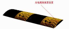
2.3. The Practical Use of the Electricity Generation System
Considering that the piezoelectric plates need discontinuous pressure to produce electricity, and according to our research, nowadays road deceleration strip is installed separately, the black and yellow rubber pieces are not disjointed. Thus, each time the vehicle passes through the strip, only the rubber piece which directly pressed by the vehicle can delivered the pressure and deformation to the electricity generation module under it, and the press can not be delivered to other pieces, which will lead to the decrease of proficiency. So that, we changed the design of the normal strip, and make sure that whatever which price gets pressure, the force can be delivered to other pieces.
Fig. 2. Road deceleration trip
302

2.4. The Design of Circuit
The Voltage Curves Produced by Series and Parallel Connection of Piezoelectric Plate
1. The Voltage Curves Produced by single Piezoelectric Plate
In the experiment, we connected single piezoelectric plate with oscilloscope, and press the plate in certain frequency and force. Through observing the voltage curve showed by the oscilloscope, we found that: The transient voltage spike was high, however the value was not stable and the spike on last for very short time; The value of current is low but stable due to the high internal resistance of piezoelectric plate.
Fig. 3. The Voltage Curves Produced by single Piezoelectric Plate
2. The Voltage Curves Produced by Series Connection of Two Piezoelectric Plates
According to basic physic knowledge, when we connect two piezoelectric plates in series, the internal resistance will increase and the voltage will be more stable. In the experiment, we connected two piezoelectric plates in serious, linked them with oscilloscope, and press the plate in certain frequency and force. Through observing the voltage curve showed by the oscilloscope, we found that: The transient voltage spike decreased but became more stable; the value of current did not change but become more stable.
303
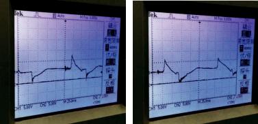
Fig. 4. The Voltage Curves Produced by Series Connection of Two Piezoelectric Plates
3. The Voltage Curves Produced by Parallel Connection of Two Piezoelectric Plates
According to basic physic knowledge, when we connect two piezoelectric plates in parallel, the internal resistance will decrease greatly and the voltage will be more stable. In the experiment, we connected two piezoelectric plates in parallel, linked them with oscilloscope, and press the plate in certain frequency and force. Through observing the voltage curve showed by the oscilloscope, we found that: The transient voltage spike did not increase but became more stable and the voltage curve showed that it became standard alternating current; the value of current increased greatly compared with serious connection due to the decrease of internal resistance.
Overall, we discovered that to achieve the best energy collecting effect, we should use the parallel connection to connect all piezoelectric plates. Through this method, we can to a large extent increase the value of voltage and current.
We connected 50 piezoelectric plates in parallel. Through observing the voltage curve showed by the oscilloscope, we found that: Comparing to the parallel connection of two, the voltage of 50 had higher frequency and peak value.
304

Fig. 5. The Voltage Curves Produced by Parallel
Connection of Fifty Piezoelectric Plate
This experiment showed that through parallel connection, we could make the output voltage become standard alternating current with high frequency and peak value.
The Module Design
Fig. 6. The Whole Module design drawing
We organized groups of electricity generation modules in to line (every module has same amount of piezoelectric plates) and connected them in parallel. Through this design, we achieved these targets:
1.All the piezoelectric plates are connected in parallel, so that the internal resistance could be dramatically decreased which makes sure the current is high enough to be stored in the accumulators.
2.When there is pressure acting on the hard rubber, this design can make sure all piezoelectric plates in one module suffer the same
305
pressure and deformation, which assures the stable of output current and prolong the duration time.
3. The Value of Practical Measurements and Estimate
3.1. Piezoelectric Effects
The Definition of Piezoelectric Effects
The nature of the piezoelectric effect is closely related to the occurrence of electric dipole moments in solids. The latter may either be induced for ions on crystal lattice sites with asymmetric charge surroundings (as in BaTiO3 and PZTs) or may directly be carried by molecular groups (as in cane sugar). The dipole density or polarization (dimensionality [Cm/m3]) may easily be calculated for crystals by summing up the dipole moments per volume of the crystallographic unit cell. As every dipole is a vector, the dipole density P is a vector field. Dipoles near each other tend to be aligned in regions called Weiss domains. The domains are usually randomly oriented, but can be aligned using the process of poling (not the same as magnetic polling), a process by which a strong electric field is applied across the material, usually at elevated temperatures. Not all piezoelectric materials can be poled.
The Equation Set of Piezoelectric Effects
Piezoelectricity is the combined effect of the electrical behavior of the material:
D E ? Di ij E j ,
where D is the electric charge density displacement (electric displacement), is permittivity and E is electric field strength, and Hooke's Law:
S sT ? Sij sijklTkl ,
where S is strain, s is compliance and T is stress.
These may be combined into so-called coupled equations, of which the strain-charge form is:
S sT ,t E ? Sij sijklTkl dkij Ek
D ,T E ? Di dijkTjk ij E j .
306
@SA sE @TA dt @EA @DA 9d:@TA T @EA
In matrix form, where [d] is the matrix for the direct piezoelectric effect and [dt] is the matrix for the converse piezoelectric effect. The superscript E indicates a zero, or constant, electric field; the superscript T indicates a zero, or constant, stress field; and the superscript t stands for transposition of a matrix.
3.2. Electric Circuits of Rectifier and Filter & The Value of Practical Measurements and Estimate
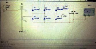
In alternating current (AC), the flow of electric charge periodically reverses direction, whereas in direct current (DC, also dc), the flow of electric charge is only in one direction. To achieve the final target that storing the electricity generated by modules in accumulator, we should deform the alternating current into direct current with the help of rectifier and filter circuits. A rectifier is an electrical device that converts alternating current (AC), which periodically reverses direction, to direct current (DC), which flows in only one direction. The process is known as rectification. Electronic filters are analog circuits which perform signal processing functions, specifically to remove unwanted frequency components from the signal, to enhance wanted ones, or both. In the end, we use voltage-regulator diode to firm the value of voltage.
Fig. 7. Electric circuits of rectifier and filter
307
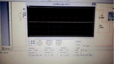
Fig. 8. The Voltage Waveform Output by Simulation Software
Through electric circuit of rectifier and filter, we achieved the high efficiency transformation from alternating current to direct current which can be restored in batteries directly.
3.3. The Value of Practical Measurements
Experiment to one electricity generation module (contains 50 piezoelectric plates), push with the power of 50N (about twice per seconds), we got:
Current: 15mA
Voltage: 4V
Resistance: 0.266k•
3.4. Calculation procedure (simulating practical situation)
The image (9) shows the calculation procedure of simulating practical situation. We inputted all the related parameter of piezoelectric plates and the frequency of press and get all the estimating generated power correlated to different stress value (the value range from 10N to 4000N).
308

Fig. 9. Calculation procedure
The image (10) is the computational results of the calculation procedure. The first row is the estimate pressure acts on the module, the second row is the generated power, and the third row is the kinetic energy that the motor vehicle would loss when it pass through the declaration stripe.
According to the output of the computational results, we found that if the pressure is controlled around the value of 1980N, one electricity generation module (constitute by 200 piezoelectric plates) could produce 0.002 KWh. Through our research towards the standard road deceleration strip, the strips’ length are determined by the practical
309

length of the road, and normally longer than 6 meters, so that each strip can at least install 100 row electricity generation module (each plates’ diameter is 40mm). The width is range from 300mm±5mm to 400mm±5mm, so that each strip can at least install 5-8 row. After calculating, we got that the whole system can generate 1KWh when one motor vehicle passed through the strip.
Fig. 10. Computational results (1000N–2000N)
4. The Other Use of the Electricity Generation System
In our daily life, taking subway is a very common way to travel. If we pay attention to the subway itself, it will be easy for us to notice that the cars of the subway have tremendous amount of weight and have great speed at run time. According to our research, we recognized that one car of the subway without passenger on it can reach a weight of 36 to 38 ton. Also, when it run to the smooth running section, its speed can achieve 80km/h. Since, the subway has tremendous weight and great speed at run time, which can be fully used by piezoelectric ceramic: the piezoelectric ceramic produce electronic through being continually pressed in high frequency, and the higher the pressure and the frequency, the more electronic it can generate, we designed
310