

журнал для КР по англ
.pdf•A rotor could do well at the first critical for too long a time during start-up and shutdown events—even when controlled acceleration and deceleration rates are employed—causing extensive damage to the unit.
Field balancing vs. at-speed balancing
A rotor can be balanced successfully in the field within its own casing and bearing system. However, access to balance planes can be a limiting factor. Some machines accommodate this requirement by adding a single access hole or a series of access points at each of the two end planes, thus eliminating the need to remove the entire upper casing half. However, if the location of the unbalance is not in an accessible plane, the correction at the end planes is only a compromise. When there is no access provision, then the whole upper casing—or parts of it—must be removed and replaced after each balancing run. A minimum of five runs is typically needed.
Balancing on the half shell
In some very extreme instances Sulzer Turbo Services has field balanced the rotor on the half shell, meaning that the upper half of the casing is left off, the lower half seal rings are removed, then the bearings are assembled and fitted. For a steam turbine rotor, an external fluid, usually dry air ported through a nozzle, is used to spin the rotor to the desired speed where readings will be taken. In the case of a large, motor-driv- en turbomachine, the drive motor is used to operate the machine to obtain the desired readings; this type is limited by the number of permissible motor starts per day. As you might imagine, this is a time-consuming prospect.
Rotating element in the field
There are significant risks and costs associated with balancing a rotating element in the field. Every time a casing is opened, there is a chance to introduce foreign objects into the flow path or to damage a
 Gas turbine rotor assembly being loaded into the bunker. The compressor and turbine sections being bolted together.
PANORAMA
component.As most machines are part of a process, the process has to be started and stopped many times to achieve the proper balance level. Imagine having to ask the operator of a nuclear facility run the fuel rods in and out a half dozen times or so over the course of four or five days so that you could accomplish something that should have been done off site, in a controlled setting, with proper equipment, during the outage cycle. To make the situation a little more uncomfortable, field balancing forces the user to adjust the rotor response to correct the combined effect of all the non-rotating items (such as misalignment, foundation resonances, piping resonances). If a rotor runs in its casing with undesirable vibration levels after being balanced at-speed it is probably not a rotor issue. A system issue will require further investigation and correction.
Acceptable levels of unbalance
Zero unbalance would always be preferred and many engineers will discuss the acceptable level for hours, given that zero is seldom economically achievable, a common level is chosen using industry standards for various types of machinery. For at-speed balancing, the American Petroleum Institute (API) requires vibration levels less than the greater of 1mm/sec, or 7400rpm.
An investment that pays well
There is rarely a more uncomfortable time in the professional life of a rotating equipment engineer, maintenance manager, or operations manager than when a critical part of their process fails to start on time, will not run, or becomes unreliable between maintenance cycles. The costs of trying to correct the issues, while accounting for lost production, can be quite staggering. Sulzer's dynamic fieldbalancing methods save both time and money over conventional site methods.
Shaun West
Sulzer Turbo Services Zürcherstrasse 12 8401 Winterthur Switzerland
Phone +41 52 262 34 44 shaun.west@sulzer.com
Sulzer Technical Review 4/2009 | 21
PANORAMA
New mist elimination technology
In many industrial processes, the entrainment of liquid in a gas stream is undesirable and can lead to damage of compressors or filler materials such as molecular sieves. In some cases, droplets of liquid in a stream of gas can cause production systems to operate at less than full throughput. Sulzer Chemtech has developed a new product for separating out these liquid droplets—the MKS Multi Cassette™ mist eliminator.
In most cases, the liquid entrained in a gas flow is in the form of droplets. The formation and the size of the droplets are determined by the process application  . In counterflow processes, such as distillation and absorption columns, the gas and liquid phases are brought into intensive contact with each other to ensure maximum mass transfer between the two phases. Structured packings, random packings, and trays from Sulzer Chemtech are optimized to increase both mass transfer and product throughput. However, one inescapable disadvantage of promoting contact
 Expected droplet size in typical processes
|
Rain |
|
Drizzle |
|
|
|
Mist |
|
|
|
Fog |
|
|
|
||
|
drop |
|
|
|
|
|
|
|
|
|
|
|
|
|
|
|
|
|
Entrainment |
|
|
|
|
|
|
|
|
|
|
|
|
|
|
|
|
from water |
|
|
|
|
|
|
|
|
|
|
|
|
|
|
|
|
cooling and |
|
|
|
|
|
|
|
|
|
|
|
|
|
|
applications |
|
spray cooling |
|
|
|
|
|
|
|
|
|
|
|
|
||
|
|
towers |
|
|
|
|
|
|
|
|
|
|
|
|
|
|
|
|
|
|
|
|
|
|
|
|
|
|
|
|
|
||
|
Spray |
produced by bubble bursting at |
|
|
|
|
|
|
|
|
||||||
|
|
a liquid-vapor interface |
|
|
|
|
|
|
|
|
|
|||||
|
|
|
|
|
|
|
|
|
|
|
|
|
|
|
|
|
process |
|
|
Entrainment from |
evaporators, |
|
|
|
|
|
|
||||||
|
|
|
|
|
distillation and |
absorption |
|
|
|
|
|
|
||||
|
|
|
|
|
|
|
|
|
|
|
|
|
|
|
|
|
|
|
|
|
|
|
|
|
|
|
|
|
|
|
|
|
|
|
|
Condensate |
|
|
|
|
|
|
|
|
|
|
|
|
|
|
Typical |
|
from gas |
|
|
|
Condensate |
from intercoolers |
|
|
|
|
|
||||
|
coolers |
|
|
|
on compression plant |
|
|
|
|
|
|
|||||
|
|
|
|
|
|
|
|
|
|
|
|
|
|
|
|
|
|
|
|
|
|
|
|
|
|
|
Condensate |
from high-pressure |
|
||||
|
|
|
|
|
|
|
|
|
|
compression plant |
|
|
||||
|
|
|
|
|
|
|
|
|
|
|
|
|
|
|
|
|
|
|
200 |
100 |
50 |
20 |
10 |
5 |
|
2 |
1 |
0.5 |
|||||
|
500 |
|
||||||||||||||
Droplet diameter (microns)
between gas and liquid phases is that this process can frequently lead to liquid being entrained into the gas flow in the form of droplets. In other processes, free liquid is formed in the gas by condensation. In this case, the generation of the droplets and their size is based on a process of nucleation, which can result in the formation of ultra-fine droplets that can be many times smaller than the droplets generated by the entrainment of liquid in counterflow columns. Liquid droplets are never all of the same size but occur in a range of sizes that may often be characterized mathematically by means of curves of log-normal distribution or Gaussian normal distribution.
The new mist elimination technology
The MKS Multi Cassette was developed with the aim of combining high liquid separation efficiency and high capacity with optimal economy. These demands required new ideas and approaches, which were put into practice in the latest mist eliminator product from Sulzer, the MKS Multi Cassette.
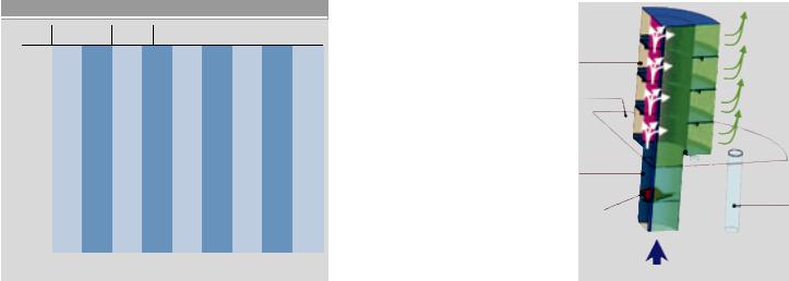
The MKS Multi Cassette consists of an inlet tube with built-in swirl element (cyclone) and the succession of separating cassettes mounted above it  . The inlet cyclone swirls the gas, thereby causing some of the droplets to be separated on to the inner wall of the cyclone: this
liquid is collected in the bottom cassette, from where it is drained. After the cyclone, the gas, still carrying the remaining entrained droplets, is distributed over the cassettes, flowing through them horizontally from the inside outwards. Each cassette is equipped with several layers of wire mesh packing which efficiently separates the remaining droplets by both direct interception (barrier effect) and inertial interception. The liquid is collected on the tray of each cassette and drained down to the next cassette by a piping system. Finally, all the liquid is collected on the bottom tray, which also
 Cut-out drawing of an MKS Multi Cassette™.
4 Cassettes |
Mist-free |
equipped with |
vapor |
structured |
|
wire demisting |
|
packing |
|
Collector |
|
tray |
|
Swirl tube
Drain pipe
Swirling elements
Vapor carries mist
22 | Sulzer Technical Review 4/2009 |
4284 |
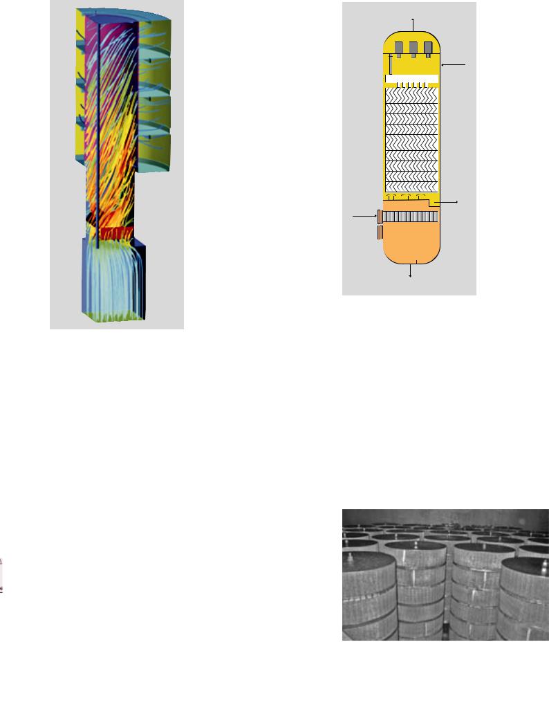
 CFD simulation with gas streamlines.
acts as support plate for the MKS Multi Cassette, and is then drained downwards out of the device through pipes. The development of the MKS Multi Cassette was supported by computational fluid dynamics simulations (CFD). The simulations performed by Sulzer Innotec enabled development engineers to check and optimize the geometry of the cyclone and the resulting gas distribution to the cassettes  .
.
Application in gas drying columns
The drying of natural gas in glycol dehydrators is a widely used process that is applied in almost all natural gas production plants in the world. Contact between the wet natural gas and glycol (often triethylene glycol, TEG) in the absorption column removes the vaporized water from the gas. Today, the use of high-capacity packing such as Sulzer MellapakPlus in absorption columns is preferred, in order to obtain minimal
column diameters or simply to maximize the natural gas throughput of the unit. Depending on the actual capacity in the column and the physical properties of the glycol, a varying amount of glycol is entrained in the gas. The droplet size in this case can be in the range of 5–25µm. To minimize the carryover, a glycol mist eliminator is required at the top of the column in order to satisfy the stipulated standard of no more than 13.7 liters loss of glycol per million standard cubic meters of gas (0.1 USgal/MMSCF). This loss expressly concerns only the glycol present in liquid form. A column equipped with Sulzer MellapakPlus™ packing requires a suitably sized highcapacity mist eliminator, since otherwise the required gas flow rate cannot be attained 
 .
.
The MKS Multi Cassette mist eliminator ideally combines with Sulzer MellapakPlus in glycol dehydrators. It meets the following outstanding qualities:
•High separation efficiency
•High capacity
•Excellent economy
•Small installation height
•Simple design
•Easy installation
•Easy maintenance
Its reliability and other qualities have already been proven in many natural gas drying columns.
Application in separators
Columns (separators) having the exclusive function of separating liquid from gas streams are used in many processes. The separation of hydrocarbon liquids from natural gas under high process pressure is always a challenge for mist
Dry natural gas
Lean TEG
Rich TEG
Wet natural gas
Liquid collected at the gas inlet
eliminators. In many cases, the cause of moisture formation is an upstream condensation process: since the surface tension between the gas and the liquid is sometimes low, very small and unstable droplets can be generated. Up to now, if the separators have to be designed for high gas flow rates or simply to save as much space and weight as possible, mist eliminators based on axial cyclones (Shell Swirltube) or vane packs (Sulzer Mellachevron) are used. However, vane
 MKS Multi Cassette ™.
PANORAMA
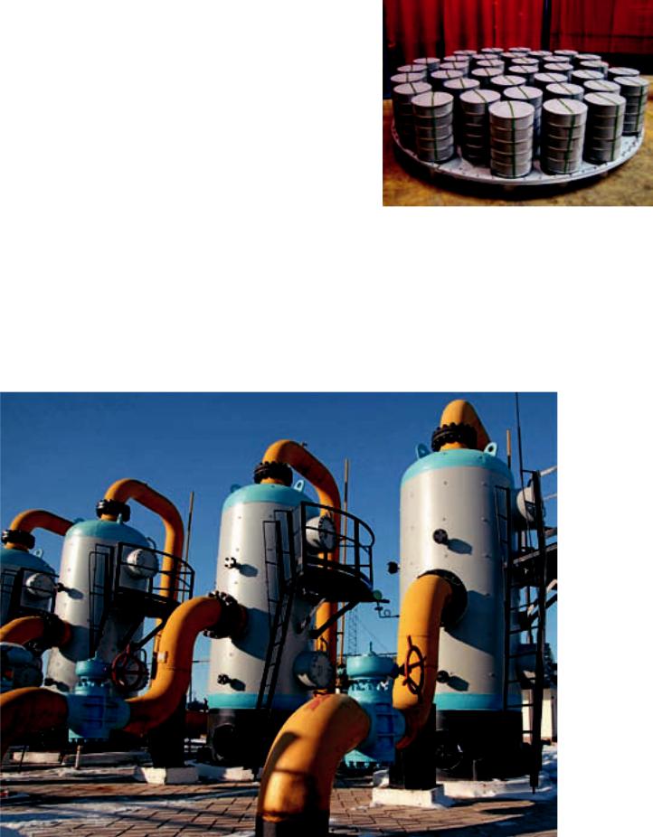
 Glycol natural gas drying column with MellapakPlus™ and MKS Multi Cassette™.
Sulzer Technical Review 4/2009 | 23
PANORAMA
pack mist eliminators are generally not recommended for high-pressure applications with liquids containing hydrocarbons and tend to have relatively low separation efficiency. Axial cyclones, like Sulzer’s Shell Swirltube, are often the first choice and are optimally designed for these tough conditions, but they also require a higher minimum available installation height in the separator. When converting separators to higher capacity, the available installation height is often limited. Also, modifications inside the column can be restricted because, in general, no additional attachments can be welded directly to the column wall.
Revamp of a KO drum to increase capacity
A revamp required the installation of high-capacity separators. However, the available installation height in the separator did not permit the installation of a Shell Swirltube with KnitMesh coalescer without major structural
modifications. The installation of a Mellachevron mist eliminator would also lead to considerable structural complications, because only the vane pack types that approximate the required separation efficiency can be considered for this application. In the end, the customer opted for the installation of the Sulzer MKS Multi Cassette, because this solution combines all the desired advantages in a single product  .
.
With the MKS Multi Cassette mist eliminator, Sulzer provides an optimal addition to the category of high-capacity mist eliminator internals. Its reliability and performance has already been demonstrated in numerous installations of natural gas dehydrators and separators. With the new MKS Multi Cassette mist eliminator, Sulzer Chemtech can offer its customers even better and more specialized custom solutions for highly complex gas-liquid separation processes. Sulzer Chemtech can also assist you in installation and commissioning.
 Sulzer MKS Multi Cassette™ for installation in a knockout drum (KO drum: A separator for removal of liquid from gas streams).
Daniel Egger
Sulzer Chemtech AG Sulzer-Allee 48 8404 Winterthur Switzerland
Phone: +41 52 262 50 08 daniel.egger@sulzer.com
© Vitaliy Hrabar, 2009 Used under license from Shutterstock.com
Gas station with several separators.
24 | Sulzer Technical Review 4/2009
SULZER HISTORY
A history of surface technology
Today's Sulzer Metco division has evolved from a number of different companies. However, a part of the roots of the company are in Winterthur.
In 1968, a small team of researchers began investigating the application of coatings using chemical vapor deposition (CVD) and thermalspraying techniques. Sulzer Metco now operates globally and offers thermal-spraying and thin-film processes as part of its portfolio of surface technologies and solutions for clients in the aviation and automotive industries, power generation, and other specialized markets.
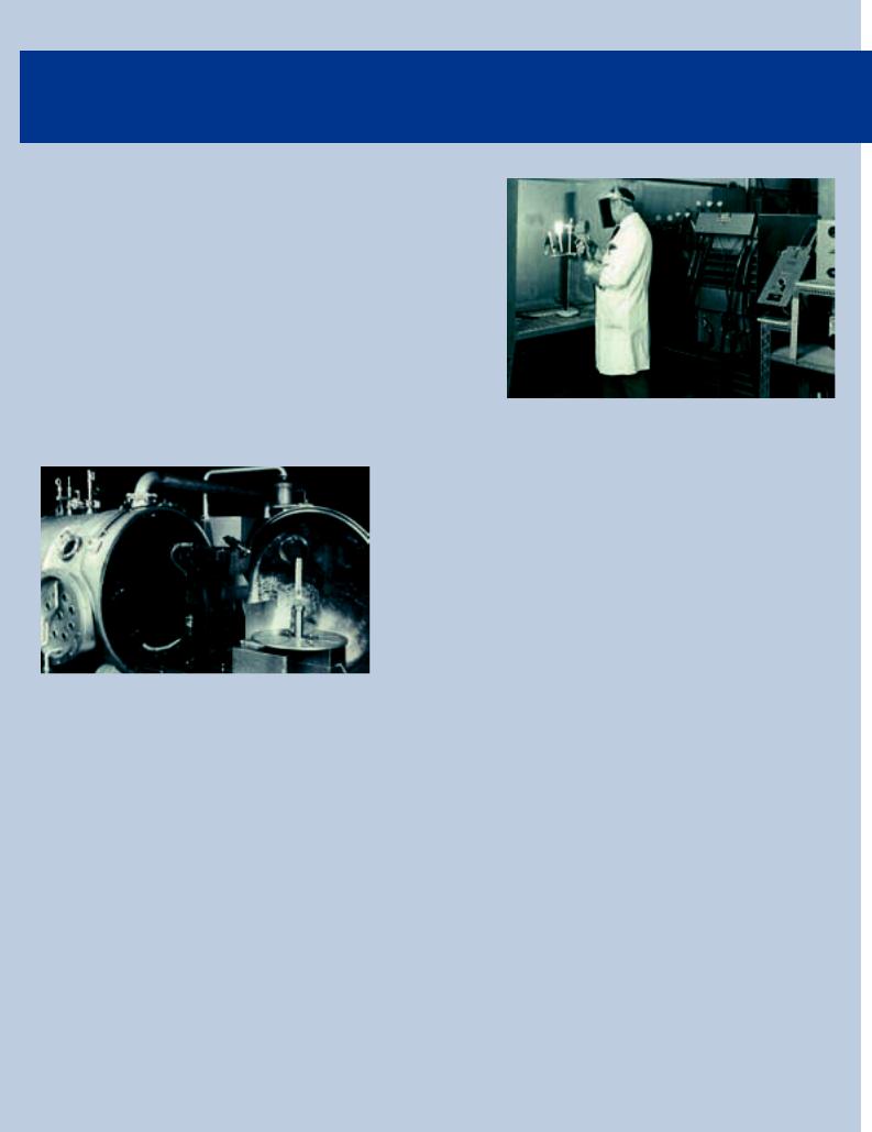
One of the first thermal-spray equipments of Switzerland.
The low-pressure thermal-spray equipment allows the coating of turbine blades.
In 1968, a team led by Hans Beutler commenced work in a new research facility—the Laboratory for New Materials. Its mandate was to develop processes to better protect surfaces against wear and corrosion and to employ new materials—such as those used in the construction of aircraft and rockets—in Sulzer products.
A superior coating
The main driving forces behind their work were the need to find better coatings for thermal turbo machines and the need to meet requirements in the fields of nuclear energy and weaving machines. The research activities focused on the CVD process, the thermal spraying of coatings, and tribology. Since it was possible to conduct several trials per day, thermal-spraying techniques developed
more rapidly than CVD, which could only process one batch daily. In the early 1970s, intensive work was carried out in conjunction with BBC (now ABB/Alstom) to develop high-tem- perature corrosion-resistant coatings for gas turbines. The plasma coating known as SS14 that was developed by the New Materials team was superior to all others. The coating of gas turbine blades was an important step forward that significantly influenced the success of Department 15 (now Sulzer Innotec) in the years that followed.
Founding of companies and acquisitions
The firm Plasmatechnik AG was founded in Wohlen in 1970, at around the same time that Sulzer in Winterthur was taking its first steps in the field of surface technology. Working in close cooperation with Sulzer, Plasmatechnik AG developed sophisticated and highly efficient plasma spray systems with a high production capacity and low rejection rates. The company was taken over by Sulzer in 1985 and subsequently integrated into the group.
In 1986, Sulzer acquired the Michiganbased firm AMI. As a result of this move, Sulzer not only expanded its product range to include spray materials and brazing but also strengthened its profile
and positioning in the USA. In 1991, the Californian company Electro Plasma Inc. was taken over by Sulzer. In the late 1970s, its owner Erich Mühlberger— the American pioneer of plasma spraying— developed the MCrAlY alloys that could be used for stationary gas turbines.
In 1994, Sulzer purchased the Metco divison of Perkin Elmer which was headquartered in New York, and combined all its companies that were active in materials and surface technologies under the name Sulzer Metco. Metco had been founded in 1933 in the USA—at the height of the Great Depression—by a graduate of the California Institute of Technology. The company, which started out with five employees, had developed into a global organization by 1994. Further acquisitions have included: Salzgitter AG in 1995; QCoat Ltd. in 1998; Eldim BV and Interturbine Coatings BV in 2000; Metaplas-Ionon GmbH and EuroFlamm GmbH in 2001; Euroflamm Select Inc. and DB Thin Filmx LLC in 2002; as well as WOKA GmbH, Ambeon, and OSU Maschinenbau GmbH in 2004.
Today, Sulzer Metco offers a broad range of surface technologies, which, combined with its experience, offer customers the very best surface solutions.
Gabriel Barroso
4285 |
Sulzer Technical Review 4/2009 | 25 |
PANORAMA
Beyond measurements
SUMEBore™ is a holistic coating solution that—depending on the application area— gives the cylinder running surfaces of internal combustion engines specific properties. This can mean, for example, lower friction and a higher resistance to corrosion.
The flow specialists at Sulzer Innotec support the application process with the help of computer-assisted flow simulations, enabling the visualization and verification of the flow situations in a cylinder during coating.
Sulzer Metco offers not only products but also complete solution packages to its customers. This
added offering allows the customer to apply the coating technology simply and efficiently. SUMEBore™ is a holistic coating solution that—depending on the application area—gives the cylinder running surfaces of internal combustion engines specific properties.
Solid lubricants
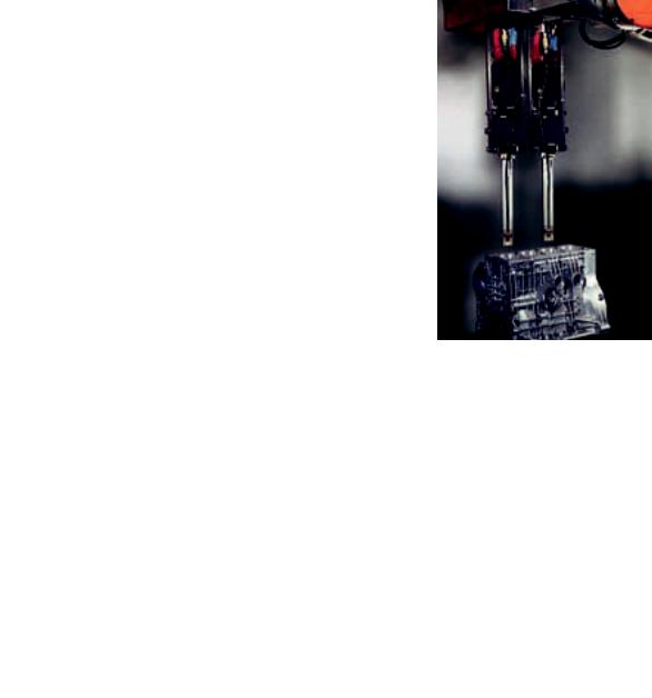
Solid lubricants can be integrated into the coating by using powders based on iron and carbon. The coating, which is applied through thermal spraying, has the desired light porosity, while the engine oil in the spray pores reduces friction—in particular during a cold start. The coating is normally applied using the RotaPlasma™ spray process—a subprocess of the SumeBore coating soluton. In doing this, a rotating, bar-shaped, and water-cooled Sulzer Metco F210 plasma gun is inserted into the cylinder that is to be coated  . Plasma guns using electrical arcs are used to heat a gas or gas mixture to more than 10000°C and to accelerate it. The added powder melts in flight, and the liquid particles create the desired coating when they impact the surface of the workpiece. Depending on
 Coating a cast-aluminum motor block with a wear-resistant layer.
the bore diameter of the cylinder, a varying number of processing steps will have to be carried out in order to achieve the desired coating thickness of approximately 200μm. Because the roughness level is around 50μm, the coating will be honed in a subsequent working process. The definitive coating thickness that is finally achieved is around 120μm.
Temperatures of more than 10000°C
Because the plasma plume reaches temperatures of more than 10000°C  and the geometrical conditions within a cylinder bore are tightly dimensioned, the workpiece will be subjected to high thermal stresses. Bores for adding compressed air are made on the rear side of the F210 burner; that way, the surfaces facing the plasma cool down directly following the coating. Compressed air is also used to focus the plasma plume optimally during the processing. An additional nozzle (shroud gas) is also located above the plasma nozzle, and serves to cool the components with cold gas (mainly argon) and shield them from the hot plasma flow
  . To ensure that the unmolten powder (overspray) causes as few flaws as possible in the coating, an additional axial airflow is forced through the cylinder bore and carries away any excess powder.
The goal of the simulation was to visualize the flow inside the cylinder and to investigate if the time and material efforts could be further reduced for the RotaPlasma spray process.
Numerical flow simulation
In order to continuously improve the process, the relationships of the complex
26 | Sulzer Technical Review 4/2009 |
4286 |
PANORAMA
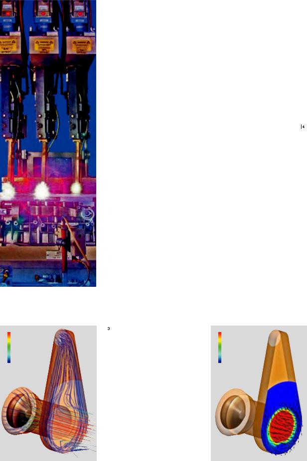
 Plasmas during the coating process.
flows have to be analyzed during the |
Two-stage modeling |
|
||
operation. However, the kinetics and the |
To improve the convergence of the |
|||
high temperatures of the process make the |
numerical analyses, the setup was split |
|||
use of measurement technology almost |
into two simulations. In a first step, the |
|||
impossible. In order to increase our |
hot nozzle flow was represented by |
|||
understanding of the process and to better |
means of an artificial heat source |
. |
||
understand the flow relationships in the |
About 9kWs are necessary in order to |
|||
operation, |
numerical flow analyses |
reach the maximum gas temperatures of |
||
(computational fluid |
dynamics, CFD) |
14000°C. The influence of the cold gas |
||
were carried out. CFD development is so |
nozzle was also taken into account in this |
|||
advanced that even complex flows can be |
first part of the simulation. The calculat- |
|||
mapped virtually. Ionized gas behaves in |
ed flow state at the nozzle outlet (values |
|||
different ways depending on the level of |
for velocity, temperature, and turbu- |
|||
ionization, and its behavior requires the |
lence) was then exported locally and was |
|||
tabular storage in the simulation program |
set into the simulation of the cylinder |
|||
of the material data correspondent to |
flow as an inlet boundary. In order to |
|||
temperature (up to 30000°C) and pressure |
minimize the outlay for the simulation |
|||
(up to 10atm). With the help of inter- |
and the associated computer time, the |
|||
polation functions, the exact gas proper- |
complete computational domain |
was |
||
ties can be taken into consideration. The |
reproduced as rotating, and the cylinder |
|||
possibility of a direct numerical coupling |
wall was stationary. This setup allowed |
|||
between the flow simulation and the |
a stationary assessment to be made of |
|||
electromagnetic system (magnetohydro- |
the flow conditions in the bore. |
|
||
dynamics, |
MHD) |
was deliberately |
With the help of this CFD analysis, it |
|
ignored in this case, because the focus |
was possible to visualize the flow situa- |
|||
was placed on the flow in the cylinder. |
tion within the cylinder bore during the |
|||
An additional cooling-gas |
max. |
nozzle is also located above the |
|
plasma nozzle, to shield the |
|
components from the hot plasma |
|
flow. The illustration shows the |
|
stream lines. |
|
|
min. |
|
[K] |
 Simulation of the hot-nozzle and cold-gas flow. Cross section at the nozzle outlet, with visualization of the temperature (colors) and velocity (arrows).
Sulzer Technical Review 4/2009 | 27
PANORAMA
max.
min.
[m/s]
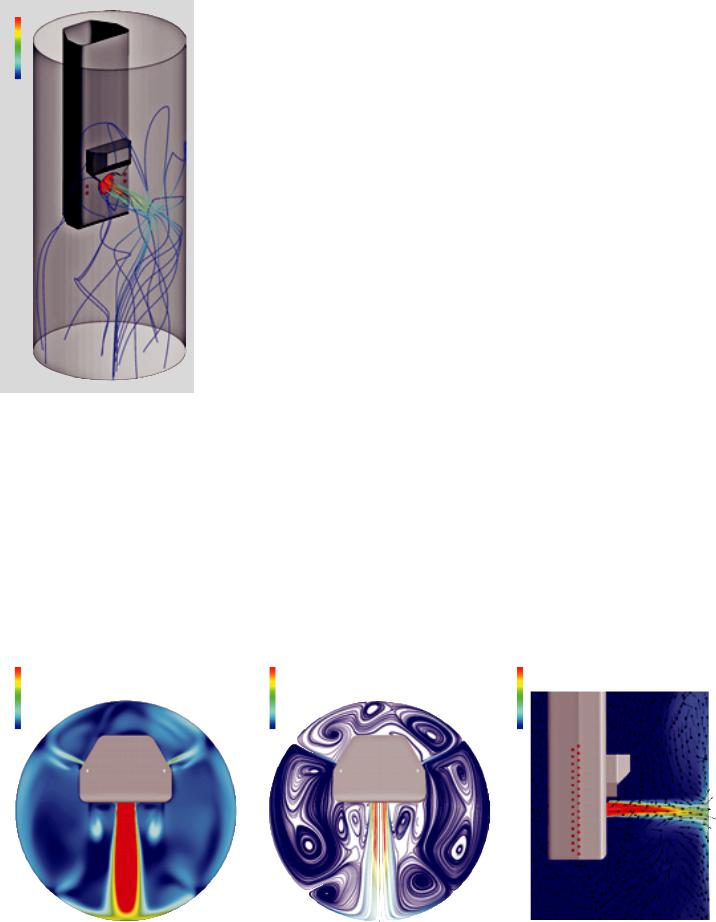
 Visualization of the flow during the coating process: 3D view of the stream lines from the nozzle.
process 
 . Spraying trials carried out beforehand had indicated the influence of the compressed air pressure on the resulting quality of the coating. For this reason, the simulations were carried out with two widely differing pressures.
If the compressed air pressure is too high, the area of influence of the cold air moves forward along the circumference of the cylinder wall towards the coating zone and interacts directly with the plasma plume where it impacts the cylinder wall. This leads to a strong instability of the flow conditions during the coating and can affect the quality of the final coating. It can even lead to particles that were already molten in the plasma becoming solid once again before impacting the wall, thereby causing flaws in the coating.
Increased process expertise
The results achieved have led to an increase in process know-how and to an adaptation of the individual process parameters. Geometric optimizations to the F210 gun were not carried out. However, the knowledge that was gained will flow into the development of new products.
With increasing computational power and increasingly accurate models, numeric flow simulation has developed into a very important design tool in the last decade and has become virtually irreplaceable in the development process of Sulzer products.
Reto Wäger
Sulzer Markets and Technology Ltd
Sulzer Innotec
Sulzer-Allee 25
8404 Winterthur
Switzerland
Phone +41 52 262 42 50
reto.waeger@sulzer.com
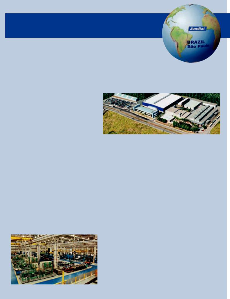
 Visualization of the flow during the coating process.
max. |
max. |
max. |
horizontal cross section (velocity) |
horizontal cross section (stream lines) |
vertical cross section (temperature) |
min. |
min. |
min. |
[m/s] |
[m/s] |
[K] |
|
|
|
28 | Sulzer Technical Review 4/2009
SULZER WORLD
Welcome to Sulzer Pumps in Brazil
Sulzer Pumps’ presence in South America and South Africa is consolidated as one business region, with headquarters in Jundiaí, São Paulo. The region has two factories: one in Brazil and one in South Africa. Following extensive investment, the site in Jundiaí, Brazil, has become one of Sulzer Pumps’ primary development, manufacturing, and distribution centers. Jundiaí also holds a strategic position within the division as a supplier of finished components and castings from its own foundry.
Sulzer Pumps’ manufacturing history in Brazil goes back to 1948, when a new factory was opened in São Bernardo do Campo, a municipality at the southern edge of greater São Paulo, Brazil’s biggest city. In 1976, a second site was inaugurated as a foundry in Jundiaí, north of São Paulo. The plant consolidation plan was a milestone that resulted in
large investments and in the Jundiaí site |
The new pump assembly hall with its state-of-the art architecture measures 7200 m2. |
|||
becoming a strategic center of develop- |
|
|
|
|
ment, manufacturing, and distribution at |
general industry. The Brazilian govern- |
cal competence, experience, and advan- |
||
Sulzer Pumps. |
ment has stated that the extensive new |
ced technology for casting play a key role |
||
Nearly 700 people in various positions |
oil reserves discovered off the Atlantic |
in supplying new equipment and asso- |
||
are needed to support the activities at |
coast (Pre-Salt Province) could turn the |
ciated services. |
|
|
Jundiaí and its affiliated service centers |
country into one of the biggest oil produ- |
Sulzer Brasil has supplied pump |
||
and sales offices in Brazil and Argentina. |
cers in the world. Brazil currently has |
packages to Petrobras for more than ten |
||
In a privileged geographical location, |
proven oil reserves of 14 billion barrels, |
oil and gas production platforms and |
||
Jundiaí can be considered an attractive |
over half of which have been discovered |
eleven refineries, some including the |
||
area for both business and employees, |
in the past five years. |
most critical and largest platforms and |
||
with easy access by road or air. It is |
Sulzer Pumps’ success in the oil and |
FPSO's (floating production storage and |
||
served by three airports well located in |
gas industry is based on providing reli- |
offloading) vessels in Brazil. Sulzer has |
||
Campinas and São Paulo. |
able high-quality equipment. The pro- |
also delivered pumps to some of the |
||
Sulzer Brasil plays a key role in provi- |
ducts are designed, manufactured, and |
country's largest water and wastewater |
||
ding engineered pump packages for the |
tested in-house. Sulzer Brasil has its own |
projects. These successes have made |
||
segments oil and gas, hydrocarbon pro- |
foundry and the largest pump test facili- |
Sulzer the leader in the Brazilian oil and |
||
cessing, power generation, water, and |
ty in the southern hemisphere. The |
gas and hydrocarbon process industry |
||
|
modern foundry produces standard and |
markets and Petrobas one of its largest |
||
Inside the new pump assembly hall at Sulzer Pumps in Brazil. |
engineered pump parts, such as impel- |
customers |
in |
the world. Through |
|
lers made of specifically designed alloys. |
the development of a diesel-hydraulic |
||
|
In-house competence allows Sulzer, as a |
driven pumping unit for firefighting on |
||
|
leading pump manufacturer, to respond |
off-shore platforms and FPSO vessels, |
||
|
to the customer’s requirements quickly |
Sulzer Pumps has reinforced its position |
||
|
and efficiently. |
as the leading pump manufacturer. This |
||
|
Furthermore, Sulzer Pumps is a long- |
year, Petrobras awarded Sulzer Brasil |
||
|
term partner of Petrobras. This Brazilian |
one of the “Best Performance Company |
||
|
international energy company, with loca- |
of 2008” prizes. This prize further |
||
|
tions in 29 countries, is the largest compa- |
strengthens |
the |
customer partnership |
|
ny in the southern hemisphere and one of |
between the two companies. |
||
|
the largest in the world. Sulzer’s techni- |
Jonas Lessa |
|
|
4288 |
Sulzer Technical Review 4/2009 | 29 |
INTERVIEW
Darayus Pardivala: “Growth of over 20% per year for the past five years”
How long has Sulzer Turbo Services been present in Houston and how many employees are now working for Sulzer Turbo Services there?
Sulzer Turbo Services has been present in Houston for 37 years. Started as Hickham Industries to service the local petrochemical industry, the company was acquired by Sulzer in 1985. Today, we have 450 employees in Houston serving the needs of customers in over 25 countries.
What is the attractiveness of Houston for Sulzer Turbo Services?
Houston serves as the repair hub for turbomachinery in the United States. With a highly skilled workforce, Houston offers Sulzer Turbo Services the ability to recruit and retain some of the best engineers and technicians in the business. The availability of reliable subcontractors in Houston is also very critical for Sulzer Turbo Services.
How many service centers do you have in North and South America and what are their capabilities?
Within North and South America, Sulzer Turbo Services has locations in Houston, New Orleans, Edmonton, Buenos Aires, Rio de Janeiro, Caracas, and Montevideo. Through these locations, we provide our
Sulzer Turbo Services provides comprehensive repair, refurbishment, and maintenance on rotating equipment on a global basis. The Head of the American business, Darayus Pardivala, spoke to us about the unit's current areas of focus.
clients with comprehensive repair and maintenance services. While the capabilities of each location vary based on market needs, Sulzer Turbo Services has the ability to leverage the expertise of all our locations to meet our clients’ expectations.
How do you make sure you know the needs of the market?
Knowing the needs of the market means knowing and understanding the specific needs of each client. While quality, competitive pricing, and speed remain the cornerstones of our culture, we strive hard to form long-term partnerships with our clients. This is why in a recent survey 98% of our clients said they would “definitely” do business with us again.
Can you give us a recent example?
A customer of ours recently suffered a catastrophic failure on a 450MW steam turbine train. Naturally, speed was of the essence, since downtime of a train of this magnitude can result in production losses of millions of dollars per week. We were able to promise our client the fastest delivery option they could find. Within eight weeks we were able to analyze the root cause of failure, redesign the rotating blades, manufacture and repair all required components, and assemble the turbine. Our client was surprised not only that our delivery on such a highly technical repair was within one
day of our original estimate, but that the project came in under our original cost estimate.
A final question: what makes Sulzer Turbo Services Houston a good place to work?
Sulzer management clearly recognizes that our most critical asset is our workforce. Thus Sulzer’s HR policy focuses on three key principles. First is creating a challenging and supportive environment for our employees. This ties in well with Sulzer’s record of promoting 70% of our worldwide leaders from within the company. Second, we make sure that we provide a safe, clean, environmentally responsible workplace. Finally, we ensure that we always have competitive compensation and benefits packages for our people. In Houston, these actions have resulted in a personnel turnover rate of less then 4%—this with a growth of over 20% per year for the past five years. This is critical to our clients and a large part of our success.
Interview: Gabriel Barroso
Darayus Pardivala
Heads the American businesses for Sulzer Turbo Services, with companies in the US, Canada, Argentina, Brazil and Venezuela. Previously, he headed the engineering department. He received his B.S. and M.S. degrees in mechanical engineering from Texas A&M University. His continued education has taken him to places like the Cambridge University Whittle Laboratory in the UK, the Jones School of Management at Rice University in Houston, Texas, and the IMD Business School in Switzerland. He has numerous publications in the turbomachinery field, and is a registered professional engineer.
30 | Sulzer Technical Review 4/2009 |
4287 |