

reading / British practice / Vol D - 1990 (ocr) ELECTRICAL SYSTEM & EQUIPMENT
.pdfUninterruptable power supply (UPS) systems
STATIC SWITCH
a
I a
|
I |
OF |
|
|
|
||
N NORMAL POSITION |
I |
I |
|
MAINTENANCE |
|||
POS ■ TiON |
|||
BY-PASS SWITCH |
|||
I A N'ENANCE POSITION
AT PASS SUPPLY 50,1Z NOMINAL
RED &BRIE PHASES ONLY
TO 4 , 5V
(gLAYN vT EvE DBNIFTt um ENT
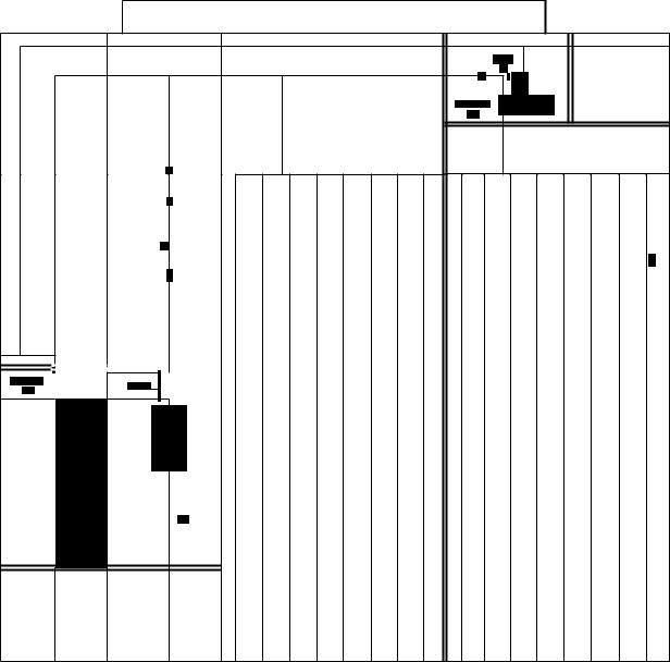
Fic. 1.34 Littlebrook D power station — unit GIS illustrating maintenance by-pass switch
being 48 hours. In order to minimise time to repair a faulty inverter system a spare set of inverter system components is provided.
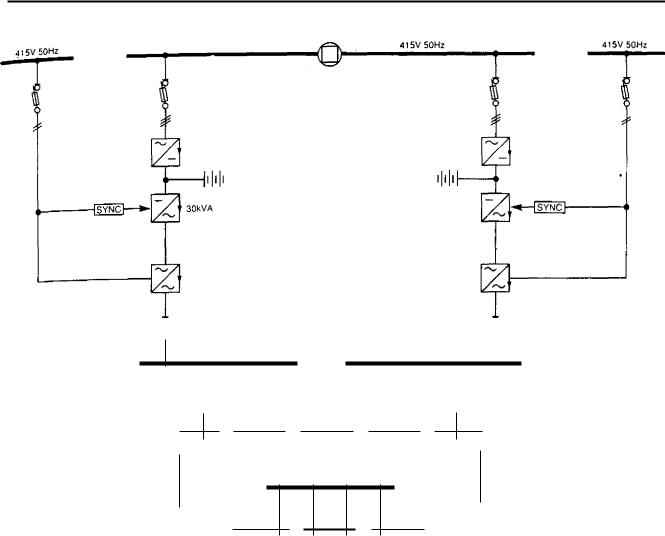
Station GM system
The station GIS system has two inverter systems, each including an associated lead-acid battery, 415 V station
GIS switchboard and a distribution network as indicated on Fig 1.36.
Either of the two inverter systems is capable of supplying the total normal station load and each battery is rated for a 30 min standby duty. This makes it possible to operate with one out of service if necessary. Under normal operating conditions the load is shared as equally as possible between the two inverter systems.
Transfer of the load from one inverter to another is only possible with a break of up to 100 ms, using the changeover contactors on the local distribution units.
53
Efectrical system design |
Chapter • |
|
|
UNIT GUARANTEED INSTRUMENT SUPPLIES DISTRIBUTION BOARD
STAND. INORMAL
STAND
•
•
FIG. 1.35 Unit GIS distribution switchboard
Local distribution units are provided for each 110 V single-phase supply point, each comprising two singlephase main and standby transformers, changeover contactors, switches and distribution switchboard as indicated on Fig 1.37. These are located around the station at suitable load centre positions.
Each 110 V AC GIS switchboard has an automatically connected standby supply arranged via changeover contactors.
The changeover scheme is almost identical to that previously described in the unit GIS section, except that a supply priority selector switch is provided.
Following a loss of supply from an inverter and its associated bypass supply, the 415 V interconnector can be closed if a prolonged outage is expected. The load
distribution units affected are then transferred back to the 'main' supply in stages.
6.3.2 Drax power station schemes
There are six 660 MW coal-fired units at this station, also six 35 MW gas-turbine generators.
Unit GIS system
with the original scheme fitted to the first three units (Fig 1.30), a 30 kVA development inverter was installed on Unit 2 in 1978. The inverter system is identical to the Littlebrook D power station type.
The unit system for the first 3 units is basically identical to the Littlebrook D power station unit sys-
54
Uninterruptable power supply (UPS) systems
415V 50Hz |
415V 50Hz |
30kVA
415V 50Hz
LOAD CENTRE
1 OV 50Hz
Fla. 1.36 Littlebrook D power station — station GIS
tem. Units 4, 5 and 6 have two separate inverter systems per unit, one for the computer and the second for all other loads. The total unit load was estimated to be in excess of one 30 kVA inverter already developed and proved on Unit 2, hence the reason for two systems per unit.
Station GIS system This is similar to the scheme previously described for the Littlebrook D station GIS in Section 6.3.1.
Each gas turbine has a separate single-phase inverter of less than 5 kVA with 110 V output and 110 V DC input. These supplies are required to enable the gas turbines to start in the absence of normal AC supplies.
6.3.3 Heysham 2 power station
This is an advanced gas cooled reactor station with two reactors and two 660 MW generating units. The UPS systems can be broadly divided into two groups:
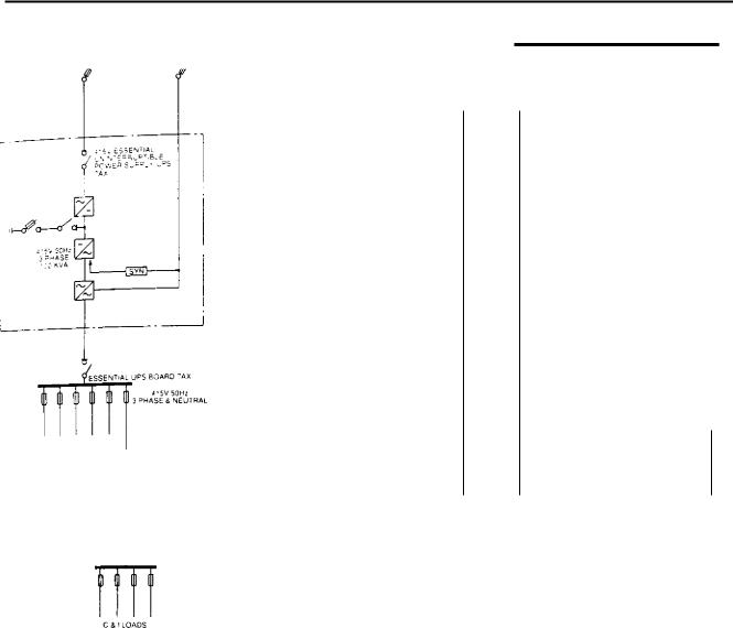
•Essential UPS systems, i.e., those required for normal reactor operation and those which are necessary for post-trip cooling of the reactor.
•Non-essential UPS systems, i.e., those which are not safety related. These are described in the section on unit and station UPS systems later in this chapter.
Each reactor is arranged into quadrants, each quadrant having two diverse modes of reactor cooling called X and Y. Consequently each quadrant has four independent UPS systems. The UPS system associated with one quadrant is shown on Fig 1.38.
415 V essential UPS system X The UPS system rating is 100 kVA and the output is 415 V. 3-phase and neutral, 50 Hz (nominal). Only essential loads are connected to this system. These are mainly control and instrumentation loads and various motors and valves. The previous advanced gas cooled reactors used motorgenerator sets for this duty.
55

Electrical system ds |
|
Chapter 1 |
|
|
|
ci)
STATION GUARANTEED INSTRUMENT SUPPLIES DISTRIBUTION BOARD
(1
FIG. 1.37 Station GIS distribution switchboard
The system has been fully type tested to very stringent requirements, including seismic tests and 11 kW motor direct-on-line starts.
The UPS battery is capable of supplying the full UPS load for considerably longer than the 30 minutes specified.
110 V essential UPS system Y This system is designed to provide both 110 V AC and 110 V DC supplies. The inverter is rated at 6.3 kVA, 110 V, 50 Hz and DC output is rated at 50 A continuous load. The loads are mainly various control and instrumentation supplies.
A standby battery and charger are provided, which can supply the inverter and DC loads of the Y 'train'
or 110 V DC loads of the X train, This equipment is also seismically qualified and in order to minimise the common-mode failure probability diverse equipment is provided for the X and Y UPS systems.
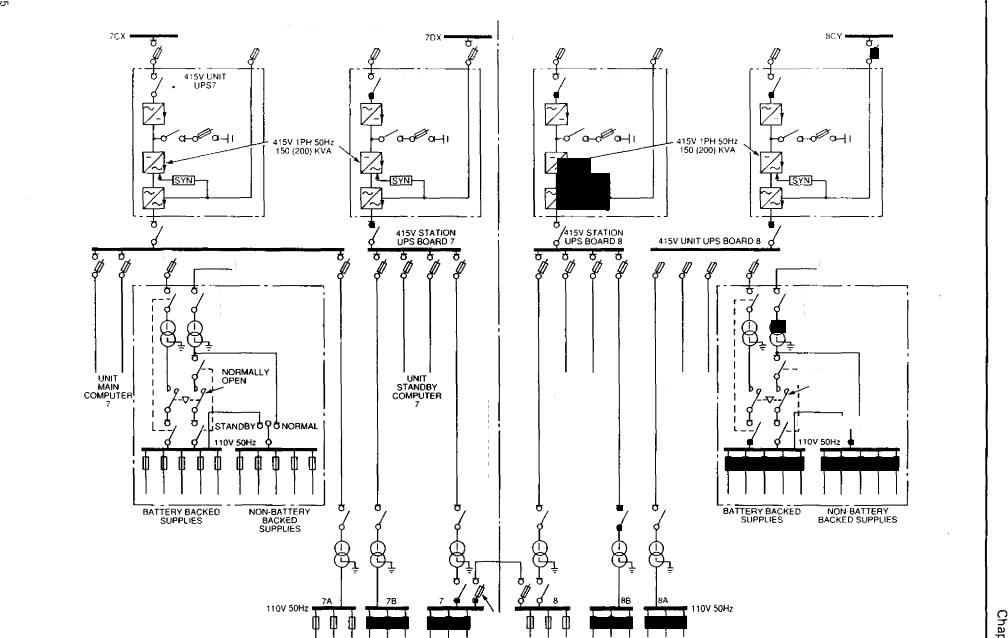
Non-essential UPS systems Unit and station UPS systems which consist of four 150 kVA, 415 V, 50 Hz single-phase UPS systems are provided at this station. Each is made up of 3 x 50 kVA inverters, a 600 A, 360 V DC battery charger and a 200 kVA static switch. The system can be expanded to 200 kVA by adding another 50 kVA inverter and another battery bank for which the stands are already installed.
Inverters operate in a redundant mode of operation providing that the load does not exceed 100 kVA limit
56
Uninterruptable power supply (UPS) systems
|
41ST ESSENTIAL SERVICES BOARO - |
|
|
4 , 55 ESSENTIAL SERVICES ECAEIC. - Ay |
|
|||||||||||||||||||||||||||||||||||
|
|
|
|
|
|
|
|
|
|
|
|
|
|
|
|
|
|
|
|
|
|
|
|
|
|
|
|
|
|
|
|
it$ |
|
|
|
|
|
|
||
|
|
|
|
|
|
|
|
|
|
|
|
|
|
|
|
|
|
|
|
|
|
|
|
|
|
|
|
|
|
|
|
|
|
|
|
|
|
|
|
|
|
|
|
|
|
|
|
|
|
|
|
|
|
|
|
|
|
|
|
|
|
|
|
|
|
|
|
|
|
|
|
|
|
|
|
|
|
|
|
|
|
|
|
|
|
|
|
|
|
|
|
|
|
|
|
|
|
|
|
|
NOT TALLY |
|
|
|
|
|
|
|
|
|
|
|
|
|
|
|||||||
|
|
|
|
|
|
|
|
|
|
|
|
|
|
|
|
|
|
|
|
"5:,' |
ESSENTIAL |
|
|
|
|
|
|
|
|
|||||||||||
|
|
|
|
|
|
|
|
|
|
|
|
|
|
|
|
|
|
|
|
|
|
|
|
|
|
|
||||||||||||||
|
|
|
|
|
|
|
|
|
|
|
|
|
|
|
|
|
|
|
OPEN |
|
|
LINI:%7EP.R.,PT.BLE |
|
|
|
|
|
|
|
|
||||||||||
|
|
|
|
|
|
|
|
|
|
|
|
|
|
|
|
|
|
|
|
|
|
|
|
|
|
POWER SU.PLY |
|
|
|
|
|
|
|
|
||||||
|
|
|
|
|
12 , 55 , ALA |
|
|
|
|
|
|
|
|
|
|
|
|
|
|
|
|
|
LAY |
|
|
|
|
|
|
'2 |
3. |
|
|
|
|
|
||||
|
|
|
|
|
|
|
|
|
|
|
|
|
|
|
|
|
|
|
|
|
|
|
|
|
|
|
|
|
|
|
|
|
|
|||||||
|
|
|
|
|
|
|
|
|
|
|
|
|
|
|
|
|
|
|
|
|
|
|
|
|
|
|
|
|
|
|
|
|
||||||||
|
|
|
|
|
STANDBY TO |
|
|
|
|
|
|
|
|
|
|
|
|
|
|
|
|
|
|
|
|
|
|
|
|
|
|
|
|
|||||||
|
|
|
|
|
X OR Y SYSTEM |
|
|
|
|
|
|
|
|
|
|
|
|
|
|
|
|
|
|
|
|
|
|
|
|
|
|
|
|
|||||||
|
|
|
|
|
|
|
|
|
|
|
|
|
|
|
|
|
|
|
|
|
|
|
|
|
|
.,--doro |
|
|
Or |
|
|
|
|
|
|
|
|
|||
|
|
|
|
|
|
|
|
|
|
|
|
|
|
|
|
|
|
|
|
|
|
|
|
|
|
|
|
|
|
|
|
|
|
|
|
|||||
|
|
|
|
|
1'05 ESSENTIAL |
|
|
|
|
|
|
|
|
|
|
|
|
|
|
|
|
|
|
|
|
|
|
|
|
|
|
|
|
|
|
|
|
|||
|
|
|
|
|
STANDBY BATTERY LA |
|
|
|
|
|
|
|
|
|
|
|
|
|
|
|
|
|
|
|
|
|
|
|
|
|
|
|
|
|||||||
|
|
|
|
To ,• Dv DC ESSENTIAL |
|
|
|
|
|
|
|
|
|
|
|
|
|
|
|
|
|
|
|
|
|
|
|
|
|
|
|
|
|
|
|
|
|
|
||
|
|
|
|
|
|
|
|
|
|
|
|
|
|
|
|
|
|
|
|
|
|
|
|
|
|
|
|
|
|
|
|
|
|
|
|
|
|
|
||
|
|
|
|
|
|
|
|
|
|
|
|
|
|
|
|
|
|
|
|
|
|
|
|
|
|
|
|
|
|
|
|
|
|
|
|
|
||||
|
|
|
|
|
|
|
|
|
|
|
|
|
|
|
|
|
|
|
|
|
|
|
|
|
|
|
|
|
|
|
|
|
|
|
|
|||||
|
|
|
|
|
|
|
|
|
|
|
|
|
|
|
|
|
|
|
|
|
|
|
|
|
|
|
|
|
|
|
|
|
|
|
|
|||||
|
|
|
|
|
BOARD LAX |
|
|
|
|
|
|
|
|
|
|
|
|
|
|
|
|
|
|
|
|
|
|
|
||||||||||||
|
|
|
|
|
|
|
|
|
|
|
|
|
|
|
|
|
|
|
|
|
|
|
|
|
|
|
|
|
|
|
|
|
|
|
|
|
|
|
|
|
|
|
|
• 5N 50Hz |
|
|
|
|
|
60Hz |
|
|
|
|
|
|
|
|
|||||||||||||||||||||||
|
|
|
3 PHASE A NEUTRAL |
|
|
|
|
|
|
|
|
|
|
|
|
|
|
|
|
|
|
|
|
|
|
|
|
|
|
|
|
|
|
|
|
|
||||
|
|
|
|
|
|
|
|
|
|
|
|
|
|
|
|
|
|
|
|
|
|
|
|
|
|
SINGLE PHASE |
|
|
|
|
|
|
|
|
||||||
|
|
|
|
|
|
|
|
|
|
|
|
|
|
|
|
|
|
|
|
|
|
|
|
|
|
|
63 K yA |
|
|
|
1 |
I |
|
|
|
|||||
|
|
|
|
|
|
|
|
|
|
|
|
|
|
|
|
|
|
|
|
|
|
|
|
|
|
|
|
|
|
|
|
|
|
|
|
|
||||
|
|
|
|
|
|
|
|
|
|
|
|
|
|
|
|
|
|
|
|
|
|
|
|
|
|
|
|
|
|
|
|
|
11 |
|
|
|
|
|
||
|
|
|
|
|
|
|
|
|
|
|
|
|
|
|
|
|
|
|
|
|
|
|
|
|
|
|
|
|
|
|
|
|
|
|
|
" |
|
|
|
|
ESSENTAL |
|
|
|
|
|
|
|
|
|
|
|
|
|
|
|
|
|
|
|
|
|
|
|
|
|
|
|
|
|
|
|
|
|
|
|
|
|
|
|
|
|
|
|
|
|
|
|
|
|
|
|
|
|
|
|
|
|
|
|
|
|
|
|
|
|
|
|
|
|
|
|
|
|
|
|
|
|
|
|
|
|
AC DR,vES |
|
|
|
|
|
|
|
NORMALLY |
|
|
|
|
|
|
|
|
|
|
|
|
|
|
|
|
|
|
|
|
|
|
|
|||||||||
|
|
|
|
|
|
|
|
OPEN |
|
|
|
|
|
|
|
|
• A, |
|
|
|
|
|
|
|||||||||||||||||
|
|
|
|
|
|
|
|
|
|
|
|
|
|
|
|
|
|
11 05 DC • ESSENTIAL BOARD 7 AY |
|
|
|
|
|
ESSEN -71AL LAS E.:',39,= |
||||||||||||||||
|
|
|
|
|
|
|||||||||||||||||||||||||||||||||||
|
|
|
|
|
|
|
|
|
|
|
|
|
|
|
|
|
|
|
|
|
|
|
|
|
|
|
|
|
|
|
|
|
|
|
|
5 |
' |
|
|
|
|
|
|
|
|
|
|
|
|
|
|
|
|
|
|
|
|
|
|
|
|
|
|
|
|
|
|
|
|
|
|
|
|
|
|
|
|
|
|
||
|
|
|
|
|
|
|
|
|
|
|
|
|
|
|
|
|
|
|
|
|
|
|
|
|
|
|
|
|
|
|
|
|
|
|
|
5.?N GLE PHASE |
||||
|
|
|
|
|
|
|
|
|
|
|
|
|
|
|
|
|
|
|
|
|
|
|
|
|
|
|
|
|
|
|
|
|
|
|
|
ooLiaLE Pc,E |
||||
|
|
|
|
|
|
|
|
|
|
|
|
|
|
|
|
|
|
|
|
|
|
|
|
|
|
|
|
|
|
|
|
|
|
|
|
|
|
|
|
|
|
|
|
|
|
|
|
|
|
|
|
|
|
|
|
|
|
|
|
|
|
|
|
|
|
|
|
|
|
|
|
|
|
|
|
|
|
|
|
|
|
|
|
|
|
|
|
|
|
|
|
|
|
|
|
|
|
|
|
|
|
|
|
|
|
|
|
|
|
|
|
|
|
|
|
|
|
|
|
|
|
|
1105 50Hz |
NOTE. ESSENTIAL UPS SYSTEM REPEATED EON EACH QuA0HANT |
SINGLE PHASE |
|
DOUBLE POLE |
|
FIG. 1.38 Heysham 2 power station — essential X and Y UPS systems
(or 150 kVA when up-rated to 200 kVA). The scheme is illustrated on Fig 1.39.
Unit Each unit has an UPS, 415 V, 50 Hz, double-pole unit UPS switchboard and a distribution network. The maximum step-down transformer rating is 16 kVA and the loads are switched-in sequentially to avoid excessive inrush current and undesirable transfer to the bypass supply.
The following loads are supplied from this system:
•Those which are required for post-incident monitoring and recordings following a main unit trip.
•Those which because of stringent supply requirements would not have adequate reliability if operated from the electrical auxiliary system only.
•Those which are required for the main unit shutdown.
The equipment upon which the reactor safety case depends is not connected to this system.
Local distribution units are provided for each 110 V single-phase supply point, each comprising two singlephase main and standby transformers, changeover contactors, switches and distribution switchboard.
These are located around the station, in the control block, etc., at suitable load centre positions. This type of distribution unit is mainly used for loads which require a single supply of high availability.
Loads which require two battery-backed supplies, e.g., microprocessor systems with plant input and output, derive one supply from the unit UPS system and the other from the station UPS system via step-down transformers.
Station UPS system This comprises two UPS systems, t wo 415 V, 50 Hz, double-pole station UPS boards
57
0c)
|
|
415V ESSENTIAL SERVICES BOARDS |
|
415V ESSENTIAL SERVICES BOARDS |
|
|||
|
7DY |
■•••■•= |
icy •1== |
|
EDT' |
8DX ■■■= |
|
|
7CX |
8C y |
|||||||
7DX |
||||||||
|
|
|||||||
|
|
|
|
|
|
|
|
|
fi
|
415V STN |
|
415V STN |
|
415V LINIT |
• |
UPS7 |
• |
UPS8 |
• |
UPSE |
|
|
|
|
|
|
|
|
- |
|
|
|
|
|
|
a-oeci-i |
|
|
a-cea-1 |
|
415V 1PH 50Hz |
|
o-cea-I |
415V 1PH 50Hz |
|||||||||
1 50 (200) KVA |
|
|
|
|
|
|
150 (200) KVA |
|
|
|
|
|
|
|
|
|
|
|
|
|
|
|
|
|
|
|
|
|
|
415V UNIT UPS BOARD 7
6
FROM 415V STATION
TURBINE SERV BD 7
TYPICAL 110V 50Hz
C & 1 SUPPLIES LOAD
CENTRE UNIT 7
461
1' '
• |
|
|
|
|
|
|
|
|
|
|
|
• |
|
415V STATION |
|
|
415v STATION |
|
|
|
|
|
|
|
|
|
UPS BOARD 7 |
|
|
UPS BOARD 8 |
|
|
4I5V UNIT UPS BOARD 8 |
|
||||
|
|
|
|
|
|
|
-6 |
-6 |
6 |
-6 |
|
|
|
|
|
|
|
|
|
||||||
6 6 6 |
|
|
|
|
|
|||||||
B
FROM 415V STATION TURBINE SERV BD 8
TYPICAL 110v 50Hz
& I SUPPLIES LOAD CENTRE UNIT 8
UNiT |
|
|
|
|
|
UNIT |
MAIN |
|
|
|
STANDBY |
||
COMPUTER |
|
|
|
COMPUTER |
||
7 |
|
|
|
|
7 |
|
|
|
|
|
|
|
|
|
|
|
STANDBY |
NORMAL |
||
|
|
|
|
|
|
|
|
|
|
110V 50Hz |
|
|
|
1 HOUR FIRE BARRIER
UNIT
STANDBY COMPUTER
8
NORMALLY
UNIT MAIN ' OPEN
COMPUTER 8
isTANDBY• • NORMAL
• |
|
|
|
• |
|
|
1 0v 50Hz |
||||
|
|
II |
IL |
II |
II |
II |
II |
II |
I |
II |
II |
|
|
|
|
|
|
|
|
|
|
|
|
|
• |
|
|
|
|
|
|
|
|
|
|
BATTERY BACKED |
|
NON-BATTERY |
|
|
|
|
|
|
|
|
|
|
|
|
BATTERY BACKED |
NON BATTERY |
|||||||
|
|
|
|
|
|
|
|
|
|
|
|
|
|
|
|
|
|||||||
SUPPLIES |
|
BACKED |
|
|
|
|
|
|
|
|
• |
|
|
|
|
|
|
|
|
SUPPLIES |
BACKED SUPPLIES |
||
|
|
SUPPLIES |
|
|
|
|
|
|
|
|
|
|
|
|
|
|
|
|
|
|
|||
|
|
|
|
|
|
|
|
|
|
|
|
|
|
|
|
|
|
|
|
|
|||
|
|
|
|
|
|
|
|
|
|
|
|
|
|
|
|
|
|
|
|
|
|||
|
|
|
|
|
|
|
a |
|
|
|
|
|
|
|
a |
|
|
|
|||||
|
|
|
|
|
|
|
|
|
|
|
|
|
|
|
|
|
|
|
|
|
|||
|
|
|
|
|
|
|
|
|
|
|
|
|
8A |
|
|||||||||
|
|
|
|
|
|
7A |
|
7B |
|
II |
• |
|
|
8B |
|
|
|
||||||
|
|
|
|
|
|
|
|
|
|
|
|
|
|
|
|
|
|
|
110V 501-1z |
|
|
||
|
|
|
110V 50Hz |
|
|
|
|
|
|
|
|
|
|
|
|||||||||
II |
II |
II |
II |
II |
II |
NORMALLY |
II |
II |
II |
II |
II |
II |
OPEN |
FiG. 1.39 Heysham 2 power station — unit and station UPS systems
aqsap walsAs Iepploal3

Uninterruptable power supply (UPS) systems
and a distribution network. Either of the two UPS systems is capable of supplying the following loads:
•Total station load.
•Standby compuier for one unit.
•Standby supply to loads of one unit which require two battery-backed supplies, e.g., microprocessor
system dth plant input and output.
Under normal operating conditions the station load is shared as e wally as possible between the two UPS systems. Transfer of the station loads from one UPS system to another is off-load at the 110 V load centres. An interlock is provided using coded keys to prevent parallel operation of the supplies derived from the two station UPS systems. Only the following C and I station loads are connected to the station UPS Boards:
•Those which are required for post-incident monitoring and recordings following loss of station AC
supplies.
•Those which because of stringent supply requirements would not give adequate standards of reliabi-
lity if operated from the electrical auxiliary system only.
•Those which are required for shutdown of any common services.
6.4 System configuration and method of operation
Each UPS has the following main components (see Fig 1.34):
•Battery charger.
•Battery.
•Inverter.
•Static switch.
•Maintenance bypass switches.
The charger and bypass AC supplies operate normally with identical frequency. Under adverse system conditions the supplies could operate at different frequencies.
Under normal operating conditions the UPS is in service and the load is normally supplied from the im, erter. The battery charger maintains the battery on float charge.
In the event of failure of the charger supply the load continues to be supplied by the battery/inverter. The load is transferred automatically from the inverter to the bypass supply without interruption in the voltage waveform under any of the following abnormal conditions, providing the inverter is synchronised in both phase and frequency to the bypass supply:
•
•Inverter failure.
•Output voltage outside the set limits.
•Excessive inverter overload or load inrush current.
•Short-circuit on the load side.
If the inverter is not in phase with the bypass supply under the above abnormal conditions, then the load is transferred automatically from the inverter to the bypass supply with a break of at least 60 ms and less than 100 ms.
The load re-transfer, back to the inverter, is completed automatically without interruption in the voltage waveform when the inverter has returned to normal and maintained a stable output for approximately 5 to 10 seconds.
Static switch redundancy
Means are provided within the static switch to parallel automatically the bypass power semiconductors, following a transfer from the inverter to the bypass supply, using a contactor or circuit-breaker. The control and power circuits are arranged to achieve a matching level of redundancy between the static and electromechanical portions of the static switch. In the event of the static portion failing to operate, the electromechanical portion operates to transfer the load automatically and/or manually from the inverter to the bypass supply with a voltage break of at least 60 ms and less than 100 ms. Following a transfer to the bypass supply, both static and electromechanical portions usually continue to operate to achieve maximum redundancy. Both portions are fully rated.
6.5 System considerations and components
6.5.1 Voltage regulation
With the inverter in service the voltage at the terminals of any instruments, control equipment and computers is maintained within + 6% to - 6% of nominal (steady state) voltage. This is achieved as follows for 415 V UPS systems:
|
Regulation |
Voltage |
|
|
adjustment |
Inverter |
+2% |
95-105% |
415 V cable between |
|
|
inverter and load |
|
|
centre |
2% |
|
415/115 V transformer |
2% |
100% +5% |
110 V cable between |
|
|
load centre and |
2% |
|
instrument or computer |
|
|
terminals |
|
|
59
Electrical system design |
Chapter 1 |
|
|
Output voltage and number of phases — 110 , 50 Hz single-phase output is usually used for ratings up to 10 kVA and where distribution cables are relatively short. One pole of the output is connected to earth and a 415/110 V bypass transformer is included.
A 415 V, 50 Hz single-phase output is used for ratings above 10 kVA, particularly where distribution cables are long. The largest single module used today is 50 k VA. The inverter output is not earthed, but is continuously monitored with an insulation monitor.
A 415 V, 50 Hz 3-phase output is used in exceptional cases where load requires 3-phases, e.g., motors. The largest rating used at present is 100 kVA.
6.5.2 UPS system loads
In order to specify a UPS system it is necessary to define the load in detail as follows:
•Load profile versus time.
•Loads requiring or generating harmonic (especially even) currents.
•Loads requiring the circulation of a DC current.
•Load steps.
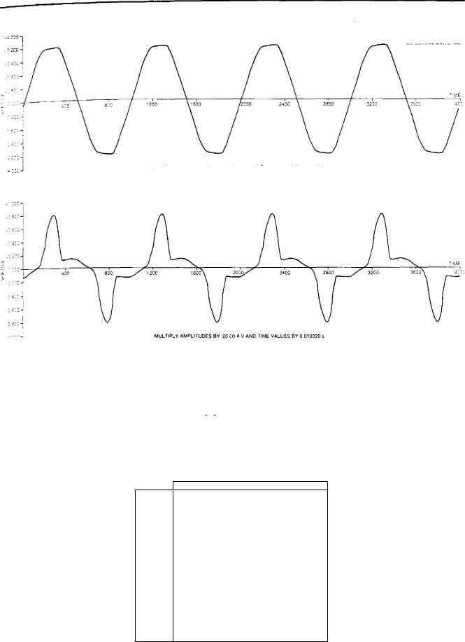
At existing installations, a survey of available loads is undertaken where access is possible. Measurements are taken using a two-channel digital oscilloscope with magnetic storage. The analysis of the waveforms obtained is carried out using a portable computer and a 'HARMD 1 program developed by the CEGB. A typical waveform and harmonic analysis are shown in Fig 1.40.
6.5.3 Step-down transformers
These have been developed to minimise the inrush currents and the associated voltage drops on the system, up to a rating of 16 kV. No ferro-resonance problems have been experienced with these transformers when switching them onto inverters.
The transformers are of the naturally air cooled single-phase double-wound type and are suitable for operation on a nominal 415 V, 50 Hz supply derived from a single-phase inverter or from two phases of the 415 V, 3-phase, 4-wire, 50 Hz (nominal), solidly earthed system with a maximum symmetrical shortcircuit fault level of 31 MVA.
The transformers comply generally with BS171, BS3535 and BEBS T2 (1966) Section 5 where applicable.
The winding insulation is Class F to BS2757 and is non-hygroscopic, but the design is such that the temperature rise limits given in 13S3535, Table 2D are not exceeded for Class E materials. The use of asbestosbased materials is not permitted.
A metallic screen is provided between the windings, one end of which is brought out and connected to the earth terminal of the transformer.
Each transformer is provided with a facility for off-load tapchanging on the 415 V primary winding. Voltage variations of +5% in 2.5% voltage steps. The method of tapchanging is by means of bolted li nks.
The nominal flux density at rated voltage and frequency and with the transformer connected on the principal tapping is specified not to exceed 1.0 tesla. The impedance voltage at rated current and frequency does not exceed 2% of the rated voltage on any tapping.
The transformers are capable of operating with nonlinear loads having relative current harmonic content of up to 50%.
The basic transformer parameters are given in Table 1.1.
6.5.4 Standby and spares philosophy
In the event of inverter failure, automatic transfer to mains supply occurs. The quality of the mains supply is acceptable for the UPS outage time, which does not therefore justify the provision of a standby UPS system.
In order to minimise time to repair, a spare set of inverter system components is kept at each station.
6.6 UPS equipment specification
As part of the development work on UPS systems, detailed technical requirements and documents for purchasing UPS equipment have been written to ensure that identified problems are overcome.
The following are brief details of the main technical requirements:
•Battery capacity The system should be capable of maintaining specified conditions for 30 minutes following complete failure of all incoming AC supplies.
The equipment should meet environmental class B3 requirements of specification CEGB-EES (1980). The ambient temperature range should be taken to be + 5 ° C to 40 ° C with air temperature not exceeding 35 ° C average in any one day and not exceeding 20 ° C average in any one year.
The equipment enclosure shall provide a degree of protection to Code IP31 of BS5490.
•Life of equipment All equipment should have a designed operating life of 30 years.
•Reliability A high degree of reliability and availability is required and the following reliability targets are specified:
|
UPS |
UPS |
|
3-phase output |
1-phase output |
|
MTBF (years) |
MTBF (years) |
Charger |
10 |
10 |
Inverter |
2 |
3 |
Static switch |
10 |
15 |
Reliability calculations are based on mean time to repair a UPS system of 48 hours.
60
Uninterruptable power supply (UPS) systems
DD DFESET REMOVED
-
MULTIPLY AMPLITUDES BY 1C0 % v v AND TIME VALUES BY O00020 $
-
|
|
|
|
|||
|
MULTIPLY AMPLITUDES BY |
2555 A V AND TIME VALUES By 0 000020 5 |
||||
Harmonic Analysis using Program HAMAD |
|
|
|
|||
Number of points for analysis :1024 |
Highest harmonic order 255 |
|||||
Number of cycles averaged |
|
4 |
|
|
|
|
Fundamental Frequency (Hz). |
50.03 |
Voltage |
Current |
|||
Total RMS |
|
|
-236- - 21V |
7 31A |
||
Peak value - - - - - - - - - - - - - |
- - |
- - - - - - - - - |
- - 319.29V - - - - - |
16.01A |
||
PeakiFtMS rano . — - - - - - - - - |
- |
- - - - - - - - - |
- - 1.35 |
2_19 |
|
|
Maximum harmonic component rRMS) _ _ _ _ — 236_05V |
6.19A |
|||||
DC level removed - |
|
|
-4.28V - - - - - |
-0.40A |
||
Relative fundamental content - |
- - |
- - - - - - - - - |
- - 99.9% - - - - - |
847% |
|
|
Relative harmonic content - - - - |
- |
- - - - - - - - - |
- - 3 7% - - - - - |
53.2% |
|
|
High frequency content ,.2 k Hz) _ |
|
- - 03% - - - - - - |
0.6% |
|
||
Total apparent power _ - - - - - - |
1.727kVA |
Total active power - - - - - - |
1.383kIN |
Power factor - - - - - - |
0 801 |
-
X |
00 |
0t. |
AAWWWWNWNN
|
Voltage |
|
|
|
Cur writ |
||
- |
|
0 |
471, |
eo |
|
|
|
a 2 |
|
— 0 G |
aulm.Nrw,i.moma-wamarro,rmm-cn , c -,:towacoaar-coaa.. -:rta.vru,nar ma . |
—NC.0,J10,4p0A00 |
|
|
|
,M! |
|
|
|
||||
0 |
|
0 -0000000000 •0100-rn 'ft, roA (n.-0 |
CD |
|
|||
00 000000000000000000ri |
|
|
|||||
, |
|
|
|
|
|
|
|
00 - |
|
|
|
|
tn |
|
|
00,10 — |
|
|
|
|
|
|
|
|
|
|
|
|
'0 |
|
|
|
|
|
|
|
|
|
|
DC components are excluded from all other parameters
CD —
o c‘iorioa•i,nu,,acn o .70t0(900,,. 141,VNLO7k0 , 40 ,1104[2.01.Nt
FIG. 1.40 Typical voltage and current waveform analysis
61
Electrical system design |
|
|
|
|
|
|
|
Chapter 1 |
||
|
|
|
|
|
|
|
|
|
|
|
|
|
TABLE 1.1 |
|
|
|
|
|
|
|
|
|
Step-down transformers |
|
|
|
|
|
|
|||
|
|
|
|
|
|
|
|
|
|
|
|
BS posker rating, kVA |
|
16 |
10 |
8 |
6.3 |
4 |
2.5 |
1.6 |
|
|
|
|
|
|
|
|
|
|
|
|
|
Number of phases |
|
1 |
1 |
1 |
1 |
1 |
I |
1 |
|
|
|
|
|
|
|
|
|
|
|
|
|
Frequency (nominal), Hz |
|
50 |
50 |
50 |
50 |
50 |
50 |
50 |
|
|
|
|
|
|
|
|
|
|
|
|
|
Rated primary voltage, V |
|
415 |
415 |
415 |
415 |
415 |
415 |
415 |
|
|
|
|
|
|
|
|
|
|
|
|
|
Rated secondary voltage, V |
|
115 |
115 |
115 |
115 |
115 |
115 |
115 |
|
|
|
|
|
|
|
|
|
|
|
|
|
Voltaee ratio at no-load |
|
415/ |
415/ |
415/ |
415/ |
415/ |
415/ |
415/ |
|
|
on the principal tapping |
|
115 |
115 |
115 |
115 |
115 |
115 |
115 |
|
|
|
|
|
|
|
|
|
|
|
|
|
Maximum impedance on any tapping, 'Yip |
|
2 |
2 |
2 |
2 |
2 |
2 |
2 |
|
|
|
|
|
|
|
|
|
|
|
|
|
Fuse links current |
|
50 |
32 |
25 |
20 |
15 |
10 |
6 |
|
|
rating at 415 V |
|
|
|
|
|
|
|
|
|
|
(to 13588-2, 1975, Class QI), A |
|
|
|
|
|
|
|
|
|
|
|
|
|
|
|
|
|
|
|
|
|
Maximum inrush magnetising current (peak), A |
|
272 |
170 |
136 |
107 |
68 |
43 |
27 |
|
|
|
|
|
|
|
|
|
|
|
|
• |
Maintenance and repair The equipment, excluding |
|
|
batteries, should not require maintenance more fre- |
|
|
quently than once annually. The mean time to repair |
|
|
the equipment should not exceed two hours. |
|
• |
Transformers and inductors |
These should have |
|
non-hygroscopic insulation with the temperature rise |
|
|
necessary to give the specified life at rated output. |
|
• |
Power semiconductor devices |
The temperature rise |
|
at the device reference point (case) shall not exceed |
|
|
50 ° C at the rated output. The maximum permissible |
|
|
temperature rise should not exceed 70 ° C under any |
|
|
operating conditions. For fan cooling this should |
|
|
apply with any single fan out of service. |
|
• |
Remote alarms and indications All locally indi- |
|
|
cated faults should be grouped into the following |
|
|
remote alarms or indications: |
|
(a)UPS system failure
(b)Inverter in service
(c)Inverter on battery
(d)Battery in service
(e)Static switch inhibited.
•Reliability monitoring A non-resetting counter and elapsed time indicator should be provided on UPS systems above 10 kVA rating for each of the following operating conditions:
(a)Inverter in service
(b)Bypass in service
(c)Static switch inhibited
(d)Inverter on battery.
6.7UPS equipment performance requirements
Charger output voltage
The charger output voltage should be automatically maintained within ± 1 % of the voltage setting when operating under any combination of the following conditions:
•Load between 0 to 100% of the rated output.
•Nominal input AC voltage ± 10o.
•Frequency 50 Hz +5%.
•Specified environmental conditions.
Inverter output voltage tolerance (steady state)
The output voltage should be maintained within +2% of the voltage setting when operating under any combination of the following conditions:
•Load between 0 to 100 07o of the rated output over the entire inverter input voltage range.
•Specified environmental conditions.
•Load power factor between 0.7 lag to unity.
Output voltage adjustment
The output voltage and adjustment shall be stepless over the range of ±5% of nominal voltage.
62