

reading / British practice / Vol D - 1990 (ocr) ELECTRICAL SYSTEM & EQUIPMENT
.pdfIRAN CARLE ROUTES
svo IC! CE AR
DIE st LS
SS
RAINS
AX
AY
EIX
BY
CX
DX
OY
|
|
Auro |
POSE I IP |
yl,QuEN(.I |
COOLING LOGIC |
EQUIPMENT |
E a/WAAL NI |
SEGREGATION OF CLASSI BARRIER OR B.B11121112.NBALid COMBINATION OF CLASS II BARRIERS
SEGREGATION OF CLASS 2 BARFBER
CIINIIUJI IURJr Lull Au
tttt t tlt I t tIt t tt U MW -
|
|
|
REG GRP:, |
REOGRHI |
|
|
buL fr, GRP 2 |
|
BuLN GRP |
|
liu,C.FLP |
|||
|
|
ROU CLUTCHES |
RCAT CLUTCHES |
ROD CLU1 COTES |
|
RCP CL LII CRCS |
|
RUD |
||||||
|
|
|
SUPPLY |
SUPPLY |
|
|
SUPPLY |
|
SL11 PLY |
|
PO:ill IONS |
|||
|
|
|
|
|
|
|
|
|
|
|
|
|
||
RA CONTACTS |
I 214 CONTACTS 1 |
|
|
|
|
|
|
|
|
|||||
|
|
|
|
|
4 |
|
|
|
|
|
|
|
|
|
|
|
|
|
|
|
|
|
|
SSD |
|
|
|
|
|
|
|
|
|
|
|
|
|
|
ERIE |
|
|
|
|
|
|
|
|
|
|
|
|
|
|
CHANNEL |
|
|
|
|
|
|
|
|
|
|
|
|
|
|
|
|
|
|
|
|
|
|
|
|
|
|
|
|
|
SSD |
|
|
|
||
|
|
|
|
|
|
|
|
|
TRIP |
|
|
|
|
|
|
|
|
|
|
|
|
|
|
CHANNEL |
|
|
|
|
|
|
|
|
|
|
|
|
|
|
2 |
|
|
|
|
|
|
GO END |
|
|
|
|
|
|
|
|
|
|
|
|
|
|
|
|
|
|
|
|
|
|
|
|
||||
|
CONTACTORS |
|
|
|
|
|
|
|
|
|
|
|
|
|
GLC END
CUNT ACTORS
SSD
TRIP
CHANNEL
III
DIVERSE GUARD INES
OLD ENO
CONTACTORS
14 1
TORT SE
FEEDS
CCA MANUAL |
|
EIC MANUAL |
TRIP |
|
TRIP |
-- SAFETY TRIP GROUPS
1SAFETY TRANSDUCERS VIA PILE CAP
A
SAIL IV I HAN,ATUL.1 TTS
1 kAiN CABLE HOWES
Lon! I. GI |
HULA, |
3 ■■■ LT "ILL CABLi 11.41 |
|
IAL AL [08 |
A., A |
1 6 MI HUGE t.H■A , SOLENOID VAL. VL CHH.Gll
TOCUBIC.3
I OCUHCL1 3
TO CUBICLE
NOTE
1 PILE CAP AND TURBINE HALL CABLING IS NOT SEGREGATED INCLuCANG COO TEMPERATURES AND FLUX HEASURENEN I S
QUADRANT AREAS
FIG. 6.2 Typical control cabling for a reactor safety trip system and post-trip cooling system
lnoAel pue swelsAs alqeD
Cabling |
Chapter 6 |
|
|
cuits and against slowly developing faults by the CCR operator.
(b)When the reactor is tripped, post-trip cooling is automatic. The possibility of spurious control signals from the CCR which could prevent effective cooling is inhibited by automatic disconnection at the switchgear/equipment remote from the CCR.
Displays associated with public hazard are normally duplicated with one display in the CCR and the other in the emergency indication centre (EIC). Cables associated with these duplicated displays should be segregated from each other to segregation Class II.
As far as the cabling to the EIC is concerned, segregation to Class II is provided between each unit. For each unit, cables associated with quadrants A and B are separated from cables associated with quadrants C and D.
Cables associated with reactor safety trip systems
Typical post-trip cooling system and safety trip cabling is shown in Fig 6.2 and, as can be seen, the reactor tripping hardware is provided on a multichannel (guard-line) fail-safe basis. The circuits are normally energised so that if the cabling associated with a particular guard-line is damaged, that guard-line will fail-safe.
Outputs from a safety group provide the inputs to guard-line equipment where they are reviewed on a redundant voting (e.g., 2 out of 4) basis. Outputs from all safety groups provide signals to each of four main guard-line (MGL) equipments which produce the necessary signals to initiate the reactor trip cooling systems. Outputs from particular safety trip groups (e.g., gas temperature) also provide signals to each of four diverse guard-line (DGL) equipments, which produce additional signals to initiate the reactor trip systems.
Outputs from the MGL and DGL equipments also provide signals to the secondary shutdown initiation (SSE) equipment. The outputs are reviewed on a redundant voting basis (e.g., 2 out of 4) in each of four channels. If the primary shutdown rods do not insert adequately, the SSI, MGL and DGL equipment provide signals on a guard-line basis to operate the secondary shutdown (SSD) nitrogen injection valves. The SSI equipment also provides signals to separately initiate the reactor post-trip cooling systems and to remove control rod clutch power supplies at the source.
Signals associated with reactor safety trip systems are run in cables separated from all other signals. Cables carrying safety trip systems are subject to the following segregation, separation and special requirements:
(a)Except for special cable requirements such as flux systems, all safety trip system cables have earthed
metal armouring or are run in earthed metal conduit.
(b)Class II segregation between pairs of safety channels of the same trip group.
(c)Class 11 segregation together with a 2 m separation distance between safety channels of the same trip group.
(d)Safety system cables are separated from singlecore power cables by at least 600 mm and from multicore power cables by at least 300 mm.
This requirement does not apply on plant or equipments at which the cable ends are terminated, provided that, for any safety system cable, the summated total of all the lengths of such cable run in parallel with power cables at less than the above stated separation distances, does not exceed 5 m.
(e)Safety system cabling carrying very low signal levels, e.g., neutron flux measurement signals, should be separated from single-core power cables by at least 600 mm and by at least 300 mm from all other cables. This requirement is applicable to the gland-to-gland route length of the cables.
(f)Separate earthed armoured cables are provided for incoming signals to the guard lines and output signals to the shutdown system. Input signal cables must be separated from output signal cables, and the routing of these cables is normally subject to special approval.
(g)All safety system cables are marked on each core at each termination with an orange ferrule, in addition to other identifying symbols.
(h)Except for cables carrying very low signal levels as (e) above, reactor safety trip system cables associated with safety channels are not required to be segregated or separated from other control cables. All reactor safety trip system cables, however, are routed along dedicated cable tray modules (which are separate to cable tray modules for other control cables) and they must be clearly identified by orange coloured bands at 1 m intervals. Groups of reactor safety trip system cables may be identified by a common orange coloured band. Conduits and trunking are similarly identified.
(i)All reactor safety trip system cables are:
•2.5 mm 2 multicore cables of the type described in Section 3.5 of this chapter, or
•0.5 mm 2 (1/0.8 mm dia.) muItipair cables of the type described in Section 3.6 of this chapter,
Or
•Special cables for thermocouple or neutron flux instrument signals.
434
|
|
|
|
|
|
|
|
|
|
|
|
Cable types |
|
|
|
|
|
||||||||||
|
Where a plant contact is being monitored for use |
level of illumination to be provided |
economically for |
||||||||||
|
in a safety trip system, the cabling to the plant |
terminating work. |
|
||||||||||
|
contact is designed to prevent the occurrence of |
As discussed in Section 2.1.1 of this chapter, major |
|||||||||||
|
a fail-danger fault due to a short-circuit between |
cable routes should be enclosed to |
provide the re- |
||||||||||
|
the go and return cable cores. Cable designs which |
quired segregation and prevent release of smoke into |
|||||||||||
|
use cables having individually screened cores are |
operational areas should a cable fire occur. Access |
|||||||||||
|
acceptable. Separate cables for each go and return |
and emergency exit points must be provided for these |
|||||||||||
|
lead should not be used. |
|
|
|
|
|
enclosed routes. The distance between emergency exits |
||||||
(k) The use of marshalling is avoided unless essential. |
is normally controlled by local regulations and pre- |
||||||||||||
mises have to be covered by a Fire Certificate which |
|||||||||||||
|
|
|
|
|
|
|
|
|
|
|
may be issued either by Fire Officers or the Health |
||
2,1.3 |
General layout requirements |
|
|
|
and Safety Executive, depending on the type of pre- |
||||||||
|
|
|
mises. For power stations, the maximum distance be- |
||||||||||
From this section so |
far, it will be evident that se- |
||||||||||||
tween escape points should be 45 m and the provision |
|||||||||||||
.,regation requirements for electrical plant and cables |
|||||||||||||
of these must be considered early in the cable system |
|||||||||||||
have a |
considerable impact on station layout. Segre- |
||||||||||||
layout. For long enclosed cable routes, it is sensible |
|||||||||||||
uation requirements must therefore be considered early |
to provide fire barriers at regular intervals across the |
||||||||||||
in the station design and one |
of the best ways of as- |
tunnel to restrict damage in the event of fire. If these |
|||||||||||
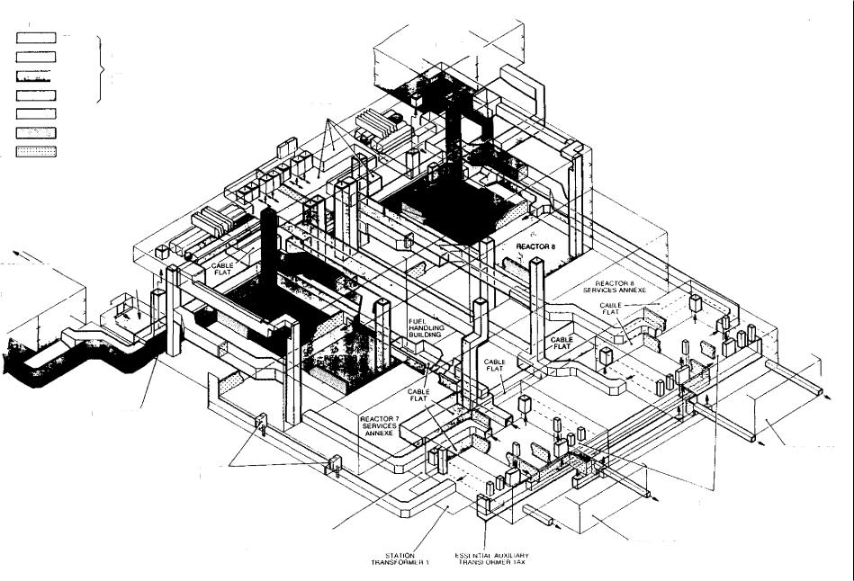
sessing problems is by the use of an isometric drawing. |
|||||||||||||
barriers are spaced at the distance required for emer- |
|||||||||||||
Figure 6.3 is an isometric drawing for an AGR station |
|||||||||||||
gency escape points, then the door through the barrier |
|||||||||||||
and, as can be seen, a different colour is used for each |
|||||||||||||
will form an escape point from a fire-affected compart- |
|||||||||||||
segregation class. Scale models can also be used to |
ment to a safe area. Major cable routes should be |
||||||||||||
assess segregation |
provisions. Such models are also |
||||||||||||
protected by a fixed waterspray fire protection system |
|||||||||||||
particularly useful |
later in the design of cable instal- |
||||||||||||
and therefore the floor areas should be tanked, and |
|||||||||||||
lations |
to check for fouls with |
other services, such as |
|||||||||||
drainage provided. |
|
||||||||||||
pipework. |
|
|
|
the importance of the |
|
|
|||||||
When considering layout, |
|
|
|||||||||||
cable installation programme must be fully recognised. |
3 Cable types |
|
|||||||||||
Cable accommodation |
must |
be made available in |
|
||||||||||
|
|
||||||||||||
good ti me and cable tunnels or basements have ad- |
The first part of this section deals with cable construc- |
||||||||||||
vantages from this point of view since they are at |
tions that are currently in common use in power |
||||||||||||
the bottom of the building and must, of necessity, be |
stations. These cable types all contain polyvinyl chlo- |
||||||||||||
scheduled early in the civil programme. If cable base- |
ride (PVC) and are designed to meet the reduced pro- |
||||||||||||
ments cannot be economically justified due to civil |
pagation performance detailed in Section 8.2 of this |
||||||||||||
engineering considerations then, as an |
alternative, |
chapter, but there has been no deliberate attempt to |
|||||||||||
dedicated overhead cable |
routes should be |
provided. |
reduce smoke, acid or toxic emissions. Such emissions |
||||||||||
Dedicated cable routes are considered essential to avoid |
are dealt with using the fire protection requirements |
||||||||||||
disruption of the cable |
installation programme due to |
detailed in the previous section. Recent developments |
|||||||||||
access being restricted |
by other contractors. Overhead |
are producing limited fire hazard cables which have |
|||||||||||
cable routes are generally |
very successful in |
boiler |
the same reduced propagation performance, but in |
||||||||||
houses, |
but for turbine halls they are more difficult |
addition have lower noxious gas emissions; a general |
|||||||||||
because the plant is more compact |
and its erection |
overview of these cable types is given at the end of |
|||||||||||
involves the turbine hall crane. It is |
difficult therefore |
the section. |
|
||||||||||
to obtain unrestricted access to install the cables which |
Before looking at detailed cable constructions it is |
||||||||||||
leave the overhead route. However, main |
overhead |
necessary to consider some of their basic components. |
|||||||||||
routes |
do have the advantage that they can support |
Firstly we should consider cable conductor material. |
|||||||||||
other services, but |
once again care must be taken that |
Ignoring special applications, the choice is basically |
|||||||||||
the installation of such services |
does not restrict access |
between copper and aluminium. Aluminium conductors |
|||||||||||
for cable installation. |
|
|
|
|
|
|
|
with a cross-sectional area of less than 16 mm 2 have |
|||||
When designing cable routes it must be recognised |
proved from experience to be very difficult to termi- |
||||||||||||
that cables are pulled -off cable |
drums and it is |
there- |
nate, because of the tendency for aluminium to 'cold |
||||||||||
fore essential that provision is |
made for cable |
drum |
flow' when put under pressure in, say, a standard screw |
||||||||||
access, normally at one end of the route only. |
|
type terminal. Copper is therefore used for power cable |
|||||||||||
Where possible the cable drum position |
should be |
conductors of cross-sectional area less than 16 mm 2 |
|||||||||||
at the highest route point to reduce pulling |
tensions. |
and for control cables. For cables having a conductor |
|||||||||||
further point to consider is the separation of ma- |
size of 16 mm 2 and greater, the choice of conductor |
||||||||||||
jor cable termination |
facilities, such as those |
in the |
material is mainly a question of economics. Aluminium |
||||||||||
CCR, from cable routes since this |
allows better ac- |
has a higher electrical resistivity than copper and to |
|||||||||||
cess to |
terminations and, in addition, allows |
a higher |
achieve comparative voltage drop and current rating |
||||||||||
435
KEY
 I I
I I
1
TRAIN A
TRAIN e CABLE TRAINS FOR
ESSENTIAL ROU IFS
TRAIN C (ESSEN 11AI SUPPLlt S
CONCERNING 1 HE QUADRANTS)
TRAIN 0
NON E SSEN FIAL ROUTES ( GENERAL PURPOSE USE)
FIRE BARRIER CLASS
FIRE BARRIER CLASS II
■...„..LOIESEL HOUSE
ESSENTIAL
SUPPLIES BUILDING
CABLE
FLAT
DIESEL HOUSE
CABLE
ESSENTIAL FLAT
SUPPLIES BUILDING
FIRE BARRIER
CLASS I
TUNNEL
ESCAPE
ESSENTIAL AUXILIARY
TRANSFORMER 1FIX
STATION |
|
|
|
kSSI NTIAL AuXILAHy |
|
TRANSFORMER |
|
T HAN S I URMEFI l AX |
DIESEL HOUSE
k |
IN I I AL |
SuPPL II S DUlL CANUS
DIESEL HOUSE
FIG. 6.3 Isometric drawing showing segregation provisions for an AGR siation

Cable types
n aluminium conductor has to have in the order of
a
1.6 times the cross-sectional area of a copper conductor. However, the specific gravity of aluminium is approximately one-third that of copper, so after taking into account the relative resistivities, the weight of an aluminium conductor would be approximately half that of copper for comparative duties. The relative ,.:osts of cables cannot be assessed on the weight of conductor material and its cost per tonne since a larger aluminium conductor results in additional insulation, armouring and sheathing materials. Because aluminium has ueater ductility than copper, solid aluminium conductors can be used in many applications and these are cheaper to produce than stranded conductors, and form a more compact cable. When assessing conductor material it is important to take into account the relative cable weights and dimensions which will affect Installation and cable support structure costs. The relative costs of aluminium and copper cable installations have varied over the years, but the considerable price advantage and improved methods of terminating resulted in the use of aluminium cables becoming established in power stations in the early 1960s. Since that time, the cost of aluminium has increased steadily vith the cost of energy, which is a dominant factor in its production. Copper, on the other hand, whilst having fluctuated in cost has not seen a large overall increase. The cost differential between aluminium and copper cables has therefore narrowed, but aluminium cables remain competitive for the majority of power applications within power stations, and are not subject to the price fluctuations associated with copper.
A further general topic is to consider the nature of polymeric materials that may be used for insulation and sheathing of cables. In the cable industry, the term polymeric material is a general term used to embrace plastics and rubbers. Rubbers are also frequently termed elastomers. Polymerics can be further classified into thermoplastic or thermosetting materials.
Thermoplastic materials are those that can be softened by heating and hardened by cooling, i.e., they can be moulded and remoulded any number of times. The most frequently used thermoplastics are polyvinyl chlo-
ride (PVC) and polyethylene (PE). Thermosetting ma-
terials, on the other hand, do not soften to any great degree below their decomposition temperature and
not capable of being remoulded. Many thermoplastic materials can be turned into thermosets by 'cross-linking'. The process of cross-linking
or vulcanisation consists of forming chemical bonds between the long chain molecules to give a 'ladder'
effect which restricts slippage between molecules and
good thermal stability. The process of cross- inking can be achieved by high energy radiation or
by chemical methods. Chemical cross-linking is the traditional method for the production of cables, but
radiation cross-linking is increasing in popularity for
Wires and small cables where insulation thicknesses are not excessive.
The most common method of cross-linking is by the addition of an agent such as peroxide to the polymer which can be activated by heat. The crossli nking agent is introduced into the polymer prior to it being extruded onto the cable. It must therefore be selected such that it is inactive at the extrusion temperature (typically 120-130 ° C). To activate the crosslinking process the polymer is normally raised to a temperature of about 200 ° C. During the curing process, gaseous decomposition of the cross-linking agent occurs and to avoid porosity of the polymer a high pressure is maintained around the insulated conductor. The curing process is carried out by passing the insulated conductor immediately after extrusion into a continuous vulcanisation line, in which the required heat and pressure for the curing process is provided. This vulcanisation line consists of a pipe attached directly to the extruder head, which is filled with high pressure steam or inert gas. After vulcanisation has been achieved in the heated portion of the pipe, the insulated core is cooled by passing through water at ambient temperature at the exit end of the pipe.
An alternative form of chemically cross-linking materials is to use a silane compound to form the links between the long molecular chains. This cross-linking method does not require heat or pressure, but is activated by moisture in the presence of a catalyst, this normally being carried out by immersion in water at a temperature of 80-90 ° C. This curing method is more competitive since it avoids the expense of continuous vulcanisation lines. Examples of thermosetting materials used for insulation are cross-linked polyethelene (XLPE) and ethylene propylene rubber (EPR).
Cables produced from thermoplastic materials such as PVC are cheaper, size for size, than those made from thermosetting materials because of the expensive plant and curing time associated with the latter.
However, cables manufactured with thermosetting insulation generally can operate at higher temperatures (both continuous and short-circuit). This may result in a reduction in conductor size and hence an overall cost saving. For example, PVC-insulated cables are normally assigned a continuous conductor operating temperature of 70 ° C and a short-circuit temperature of 160° C, compared with 90 ° C and 250° C respectively for thermosetting materials such as XLPE and EPR.
Finally, it is worth noting that it is normal practice to separate power and control cables to reduce electromagnetic interference and, to enable this separation to be checked on site, power cables have black sheaths whilst control cable sheaths are coloured grey.
3.1 11 kV cables
For II kV cables, the choice of insulant rests between paper or polymeric. Paper insulated cables have lead or alloy sheaths and in consequence are heavier and more difficult to install and terminate than plastic
437
Cabling |
Chapter 6 |
|
|
|
|
insulated cables. More importantly, plastic insulated cables can be made considerably more fire retardent than paper cables and therefore plastic cables are selected for power station applications.
The design and testing of such cables with solid extruded insulation is specified in Generation Development and Construction Division (GDCD) Standard 17 which covers single-core cables having cross-sectional areas of 300 mm 2 and 500 mm 2 . Single-core cables are selected primarily because of the fault levels associated with power station 11 kV systems. Since circuitbreakers are used for switching, the fault current is not restricted as it might be at lower voltages where fuses are employed in many instances. For 11 kV, 750 MVA fault rated systems, the RMS symmetrical value of fault current for phase faults is 39.4 kA, with a first peak as high as 121 kA. The electromechanical forces associated with such currents could result in three-core cables 'bursting', i.e., the outer coverings of the cable being torn open by the repulsive forces between the conductors. A further item to be considered is that it is normal practice to earth the neutral of 11 kV systems via a neutral earthing resistor, which will restrict the earth fault current per feed to approximately 1 kA. Under these circumstances it is quite clearly worthwhile taking steps to avoid phase faults, which can be extremely destructive. The use of singlecore cables means that any faults that occur within the cable must be between conductor and the screen (or armour) which is earthed, hence the fault current will be restricted by the neutral earthing resistor. Finally, the resistive heating effect in the conductor under short-circuit conditions dictates a minimum conductor size that would render three-core cables physically large and heavy for installation.
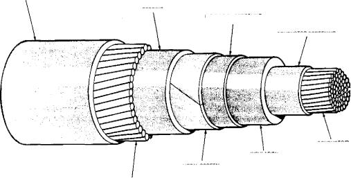
The construction of single-core cables with solid extruded insulation is given in Fig 6.4. The preferred
insulation is of the thermosetting type, i.e., XLPE or EPR, which gives a conductor continuous operating temperature of 90 ° C and a short-circuit temperature of 250 ° C. Thermosetting materials give significant benefits since the size of 11 kV cables is frequently dictated by short-circuit requirements, indeed the minimum aluminium conductor size of 300 mm 2 normally prescribed in power stations is derived from this consideration. For comparable duty, a paper insulated cable having a maximum short-circuit temperature of 160 ° C would require a minimum aluminium conductor size of 400 mm 2 .
The electrical stress in the insulation for these cable designs is in excess of 2 kV/mm and this necessitates the use of conductor and core screens for stress control. Figure 6.5 shows the stress distribution in a well screened cable where the exponential lines are concentric and the flux lines are evenly distributed. Figure 6.6 shows the stress distribution for a cable without a conductor screen, and here it can be seen that the equipotential lines are deformed and become bunched together at the protruding conductor strands, giving high electrical stress in the insulation at these points. Such high stresses may cause a local breakdown in the insulation known as a partial discharge, which can cause erosion of the dielectric and ultimately complete breakdown of the cable. A similar situation can occur on the outer surface of the insulation and Fig 6.7 shows the effect of an incomplete core screen. The conductor core screen normally consists of an extruded layer of semi-conducting material frequently applied over a semi-conducting support tape, which prevents the extruded material being 'lost' between the conductor strands. The insulation screen may be either an extruded layer of semi-conducting material or a semiconducting varnish applied direct to the insulation surface, with a semi-conducting tape applied over it
OVERSHEATH
BEDDING
INSULATION SCREENING
SEMI.CONDUCTING
CONDUCTOR SCREENING
CONDUCTOR
INSULATION
METAL SCREEN
WIRE ARMOUR
FIG. 6.4 11 kV single-core cable construction
438

Cable types
CONDUCTOR SCREEN
INSULATION SCREEN
FIG. 6.5 |
Stress distribution in cable insulation |
|
|
|
|
|
EOUIPOTENTIAL LINES |
Fic. 6.7 Stress distribution with section of core |
|
|
screen missing |
FIG. 6.6 Stress distribution in cable without a conductor screen
as protection against mechanical damage from the metallic screen. Where extruded screens are used, these should be 'cold strippable' to ease the process of terminating. A helically-applied copper tape screen is provided over the semi-conducting insulation screen
to carry both leakage and fault currents. The copper tape is designed to carry an earth fault current of
1 kA for one second. A PVC inner sheath is provided over the copper tape to provide a bedding for the armour wires. This inner sheath also performs the important function of a secondary moisture barrier
to prevent water reaching the primary insulation in the event of the outer sheath being damaged. The
cable construction is completed by applying a layer
of aluminium armour wires, these being non-ferrous to avoid eddy current heating, and finally a PVC outer sheath.
It is important to ensure outer sheath integrity to prevent water entering the cable and because the cable armour will have standing voltages due to single-point bonding of the armour (see Section 11 of this chapter). A semi-conducting layer is therefore applied to the outer sheath to allow effective electrical testing between this and the cable armour to demonstrate sheath integrity.
3.23.3 kV cables
3.3kV systems in modern power stations can have a fault level of up to 250 MVA, which gives a phase fault current of 43.7 kA, and neutral earthing resistors
are fitted to restrict earth fault currents to 1 kA per feed. The situation is therefore similar to that for 11 kV described in the previous section, and single-core cables are again prescribed for 3.3 kV circuit-breaker fed equipment. This type of application frequently consists of short tails of cable from transformer to switchgear, where full advantage can be taken of the higher continuous operating and short-circuit temperatures of thermosetting materials.
Such single-core cables are purchased to the general requirements of IEC 502, the constructional make up being shown in Fig 6.8. A stranded aluminium conductor with a minimum cross-sectional area of 400 mm 2 is required to meet the short-circuit requirements detailed above, and this size will normally be adequate for all applications. The insulation consists of XLPE
439

Cabling |
Chapter 6 |
|
|
Ov E RS H E A TH
WIRE ARMOUR
Ftc. 6.8 3.3 kV single-core cable construction
or hard ethylene propylene rubber (HEPR) having a radial thickness of 2 mm. The cable is finished in a si milar manner to that for 11 kV by applying a PVC inner sheath, aluminium wire armour and PVC outer sheath. Once again, a semi-conducting coating is applied to the outer sheath to facilitate electrical testing.
In the interests of switchgear economy, circuits such as motors and small transformers are fed from fused switching devices (FSD) wherever possible. As described in Chapter 5, a fused switching device consists of a s mall circuit-breaker capable of interrupting up to about 10 kA which is protected from higher fault currents, by fuses. Whilst these fuses are provided primarily to protect the switching device and ensure satisfactory short-circuit fault clearance, they also provide protection to the circuit cables attached to them. Because
the fault current is 'cut-off', the short-circuit power and electromagnetic forces are reduced allowing three-core cables to be used. Under these conditions, thermosetting insulation offers no significant cost advantage over thermoplastic insulation.
Three-core cables suitable for this application are detailed in BS6346 and the constructional arrangement is shown in Fig 6.9. The conductors are solid shaped aluminium and cross-sectional areas of 150 mm 2 and 240 mm 2 are normally adequate for power station applications. The minimum cable size of 150 mm 2 is related to a fuse size of approximately 400 A which is the maximum fuse rating for a FSD. The 240 mm 2 size is considered adequate to handle the largest size of load that can be connected to a FSD. The insulation, inner and outer sheaths consist of extruded layers of
EXTRUDED OVERSHEATH |
ALUMINIUM STRIP ARMOUR |
|
EXTRUDED INSULATrON
CONDUCTOR
EXTRUDED BEDDING
FIG. 6.9 3.3 kV multicore cable construction
440
|
|
|
|
|
|
|
|
|
Cable types |
|
|
|
|
|
|
||||||
p VC. The armour on these cables is aluminium strip |
return path for earth fault currents. Whilst the armour |
|||||||||
|
improve conductivity, since it is used as an earth |
of the small copper cables is also utilised for the earth |
||||||||
to |
|
|
|
|
fault return path, the smaller fuse sizes associated with |
|||||
fault current return path, as discussed in Section 11.5 |
||||||||||
|
this chapter. These three-core cables have a maxi- |
these circuits allow steel wire armour to be specified. |
||||||||
of m continuous conductor temperature of 70 ° C and |
|
|
|
|||||||
mumaximum short-circuit conductor temperature of |
|
|
|
|||||||
3 |
|
|
|
|
|
|
3.4 Cables for DC power circuits |
|||
I 60° C. |
|
|
|
|
||||||
|
|
|
|
The cables detailed in the previous section for 415 V AC |
||||||
|
|
|
|
|
|
|
||||
3,3 415 V cables |
|
|
circuits are also suitable for use on DC circuits. The |
|||||||
|
|
largest two-core cable listed in the rationalised cable |
||||||||
Sinde-core cables are selected for use on equipment |
range given in Table 6.2 is 70 mm 2 . Where cross- |
|||||||||
,:ontrolled by circuit-breakers. Once again the insulant |
sectional areas in excess of this size are required, it is |
|||||||||
selected for these single-core cables is XLPE or EPR |
normal practice to use a four-core cable with its cores |
|||||||||
,,ince advantage can be taken of the 90 ° C continuous |
paralleled such that two cores are used for each pole. |
|||||||||
and 250 |
° C short-circuit temperatures. The construction |
|
|
|
||||||
and dimensions of these cables are identical to those |
3.5 Multicore control cables |
|||||||||
for use on 3.3 kV systems. Once again a rationalised |
||||||||||
conductor size of 400 mm 2 stranded-aluminium will |
Multicore control cables suitable for use in power sta- |
|||||||||
be found suitable for short-circuit requirements and |
tions are manufactured to ESE Standard 09-6, Section |
|||||||||
all normal full-load current applications. |
||||||||||
1. These come in a range of sizes from two-core up to |
||||||||||
|
Multicore cables are selected for use on fuse pro- |
|||||||||
|
37-core and are rated at 600/1000 V. These cables |
|||||||||
ieLL:ted circuits. On 415 V fuse protected circuits, the |
||||||||||
consist of a 2.5 mm |
2 |
(7/0.67 mm dia.) stranded-copper |
||||||||
Li miting criterion for cable sizing is frequently volt- |
|
|||||||||
conductor with PVC insulation. The required number |
||||||||||
drop and therefore no advantage can be taken of the |
of cores is then laid-up with an overall plastic binder |
|||||||||
hi der operating temperature of thermosetting insula- |
||||||||||
tape, extruded PVC inner sheath, steel wire armour |
||||||||||
ti ons; 600/1000 V thermoplastic insulated cables com- |
and PVC outer sheath. The cores are numbered for |
|||||||||
plying with 856346 are therefore specified. |
identification purposes. The steel wire armour is pro- |
|||||||||
|
For cable sizes 16 mm 2 and above, the conductors |
|||||||||
|
vided for mechanical protection and to improve the |
|||||||||
are solid aluminium, these being circular for the 16 |
||||||||||
reduced fire propagation performance. |
||||||||||
mm 2 size and shaped for larger sizes. The cables have |
||||||||||
|
|
|
||||||||
extruded PVC insulation, a taped PVC inner sheath, |
|
|
|
|||||||
aluminium strip armour and extruded PVC outer sheath. |
3.6 Multipair control cables |
|||||||||
For cable sizes of less than 16 mm 2 , circular stranded- |
Multipair control cables are manufactured and tested |
|||||||||
copper conductors are used covered with extruded PVC |
||||||||||
to the requirements of GDCD Standard 200 in a range |
||||||||||
insulation, extruded inner sheath, steel wire armour |
||||||||||
of sizes from two-pair up to 200 pairs. These cables |
||||||||||
and extruded outer sheath. To ease bulk ordering and |
||||||||||
use plain solid annealed-copper conductors having a |
||||||||||
)tocking difficulties a rationalised range of cable sizes |
||||||||||
Ls shown in Table 6.2. |
|
|
cross-sectional area of 0.5 mm 2 (1/0.8 mm dia. wire), |
|||||||
|
Aluminium strip armour has been selected for the |
which are insulated with an extruded layer of PVC. |
||||||||
|
Two insulated cores are twisted together to form a |
|||||||||
larger cable sizes because it is utilised as the main |
||||||||||
pair and then pairs are laid-up to form the required |
||||||||||
|
|
|
|
|
|
|
||||
|
|
|
|
|
|
|
cable size. The two-pair cable does not actually consist |
|||
|
|
|
|
TABLE 6.2 |
of two pairs, the four cores being all laid-up together |
|||||
|
|
|
|
in what is known as a quad formation. For cables |
||||||
|
|
|
|
Raiionalised range of cable sizes |
||||||
|
|
|
|
|
|
|
having greater than 20 pairs, a unit construction is |
|||
Conductor |
Number of |
Construction |
used. This means that the cable contains a number |
|||||||
CSA, mm 2 |
cores |
|
|
of 20-pair units, each 20-pair unit having the same |
||||||
|
|
|
|
|
|
|
colour coded core sequence, and a numbered binder |
|||
2.5 |
|
2, 3 and 4 |
|
|
||||||
|
Cu/PVC/PVC/SWA/PVC |
tape to enable one unit to be identified from another. |
||||||||
4 |
|
|||||||||
|
2, 3 and 4 |
Cu/PVC/PVC/SWA/PVC |
The colour code is in accordance with IEC Standard |
|||||||
6 |
|
2, 3 and 4 |
Cu/ PVC/PVC/SWA/PVC |
189.2. An overall screen is applied over the laid-up |
||||||
16 |
|
2, 3 and 4 |
AI/PVC/PVC/ALS/PVC |
pairs and in the case of 5-pair and larger cables this |
||||||
|
|
|
|
is formed from a longitudinally-applied aluminium la- |
||||||
35 |
|
2, 3 and 4 |
AI/PVC/PVC/ALS/PVC |
|||||||
|
minate. A tinned-copper 'drain wire' is provided under |
|||||||||
|
|
|
|
|||||||
70 |
|
2, 3 and 4 |
AI/PVC/PVC/ALS/PVC |
|||||||
|
and in contact with the aluminium screen, to enable |
|||||||||
120 |
|
|||||||||
|
3 and 4 |
Al/PVC/PVC/ALS/PVC |
it to be connected to earth. An extruded inner sheath |
|||||||
185 |
|
|||||||||
|
3 and 4 |
AI/PVC/PVC/ALS/PVC |
is applied over the screen which strongly adheres to |
|||||||
300 |
|
3 and 4 |
|
|
the plastic backing of the aluminium laminate. Cables |
|||||
|
|
|
|
|
|
|
containing 20 pairs and greater are armoured using |
|||
|
|
|
|
|
|
|
||||
441

Cabling |
Chai. |
|
|
double-galvanised steel tape armour. Steel wire armour is used for 2, 5 and 10-pair cables which are too small in diameter for steel tapes to be applied. The cables are sheathed overall with an extruded layer of PVC. The range of cable sizes includes 2, 5, 10, 20, 40, 60, 100 and 200 pairs. These cables are suitable for use at voltages up to and including 110 V AC or 150 V DC.
The aluminium laminate screen provides a moisture barrier to prevent ingress of moisture to the cores as well as being an effective screen against higher frequencies. The steel tape armour provides power frequency screening.
3.7 Short- ti me fireproof cables
A short-time fireproof (STFP) cable is one that, under test conditions, will remain serviceable for 20 minutes when exposed to a flame temperature of 1000 ° C.
These STFP cables are available as both multicore and multipair designs, their construction and testing being specified in GDCD Standard 195. The multicore design has 2.5 mm 2 (7/0.67 mm) stranded-copper conductors laid-up in 2, 3 and 4 core cable constructions. The multipair design has 0.5 mm 2 (1/0.8 mm dia.) solid copper conductors laid-up into 2, 5 and 20 pair constructions. The detailed cable construction is not standardised as manufacturers like to use their own special designs. However, all cables are required to be steel-wire armoured and sheathed for mechanical robustness. The electrical performance of these special cables is required to be equivalent to the standard cables detailed in Sections 3.4 and 3,5 of this chapter. The special fire performance of these cables is achieved by appropriate primary insulation. Examples of materials that can be used are silicone rubber or ethylene propylene rubber in conjunction with mica tapes or glass braid.
These types of cables are expensive compared with conventional cables and their use has therefore to be limited. Typical applications are selected trip and protection functions, audible warnings and communication circuits that it is essential to keep in service under fire conditions.
3.8 Linear heat detecting cables
With the growing concern regarding the considerable damage that can occur to power station installations under fire conditions, means of rapid fire detection have been sought. Linear heat sensors in the form of cables which can detect relatively small increases in temperature are one solution. These are particularly effective for fire detection in cable routes when a linear heat detecting cable (LHDC) is mounted over each cable tray.
Linear heat detecting cables are manufactured and tested to the requirements of GDCD Standard 187 which covers two different types of sensors.
The first category covers 'digital' type detectors a general arrangement of one of these is shown Fig 6.10. These generally consist of two steel wire ductors that have been insulated with a suitable
moplastic material and twisted to form a pair. At th,
5TEE WIRE
THERMOPLASTIC
TAPE
OUTER COVERING
FIG. 6.10 Digital-type linear heat detecting cable
set operating temperature the thermoplastic softens, allowing the steel conductors to move and short-circuit. Different operating temperatures can be obtained by small variations in the cable design. The short-circuit that occurs at the set operating temperature can be used to initiate alarms or fire protection systems.
The second category covers 'analogue' type detectors and a typical arrangement is shown in Fig 6.11. In this type of detector, the insulation is specially formulated to have a rapid rate-of-change of resistance with temperature. The resistance of the detector is monitored and any change beyond a set point relating to the required operating temperature is used to trigger the required alarm or fire protection systems.
3.9 Developments in cable design
The current awareness of noxious gas emission from cable fires has brought about a rapid development in cable compounds to replace high halogen content materials such as PVC. Cables constructed with these new compounds are generally known as 'limited fire hazard' designs. Suitable fire tests to assess reduced
442