

plc software - 32.8
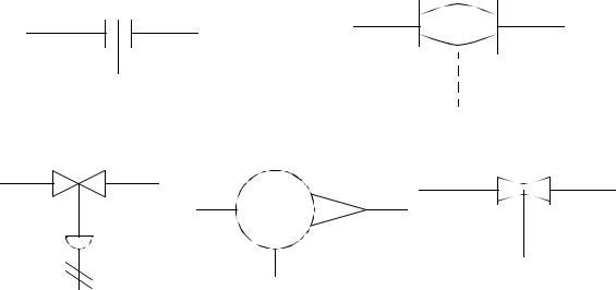
orifice plate |
magnetic |
|
venturi or nozzle
control valve |
rotameter |
|
|
(pneumatic activated) |
|
Figure 32.4 Sensor and Actuator Symbols and Types
32.4 PROGRAMMING FOR LARGE SYSTEMS
Previous chapters have explored design techniques to solve large problems using techniques such as state diagrams and SFCs. Large systems may contain hundreds of those types of problems. This section will attempt to lay a philosophical approach that will help you approach these designs. The most important concepts are clarity and simplicity.
32.4.1 Developing a Program Structure
Understanding the process will simplify the controller design. When the system is only partially understood, or vaguely defined the development process becomes iterative. Programs will be developed, and modified until they are acceptable. When information and events are clearly understood the program design will become obvious. Questions that can help clarify the system include;
"What are the inputs?" "What are the outputs?"
"What are the sequences of inputs and outputs?" "Can a diagram of the system operation be drawn?"
plc software - 32.9
"What information does the system need?" "What information does the system produce?"
When possible a large controls problems should be broken down into smaller problems. This often happens when parts of the system operate independent of each other. This may also happen when operations occur in a fixed sequence. If this is the case the controls problem can be divided into the two smaller (and simpler) portions. The questions to ask are;
"Will these operations ever occur at the same time?"
"Will this operation happen regardless of other operations?" "Is there a clear sequence of operations?"
"Is there a physical division in the process or machine?"
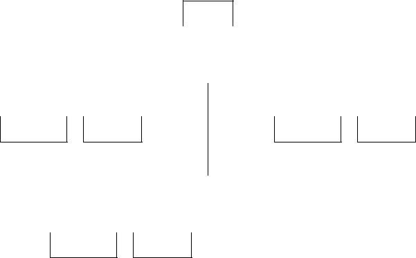
After examining the system the controller should be broken into operations. This can be done with a tree structure as shown in Figure 32.5. This breaks control into smaller tasks that need to be executed. This technique is only used to divide the programming tasks into smaller sections that are distinct.
Press
|
|
|
|
|
|
|
|
|
|
|
|
|
|
|
|
|
|
|
|
|
|
|
|
|
|
|
|
|
|
|
|
|
|
|
|
|
|
|
|
|
|
Conveyor in |
|
|
|
Press |
|
|
|
Pickup bin |
|
|
|||||||
|
|
|
|
|
|
|
|
|
|
|
|
|
|
|
|
|
|
|
|
|
|
|
|
|
|
|
|
|
|
|
|
|
|
|
|
|
|
|
|
|
|
|
|
|
|
|
|
|
|
|
|
|
|
|
|
|
|
|
|
part detected |
advance |
bin replaced |
full detect |
|
|
|
|
|
|
|
|
|
|
|
|
|
|
|
adv./retract |
|
|
idle |
|
part detect |
|||||
|
|
|
|
|
|
|
|
|
|
|
|
|
|
|
|
|
|
|
|
|
|
|
|
|
|
|
|
|
|
|
|
|
|
|
|
|
|
|
advancing retracting
Figure 32.5 Functional Diagram for Press Control
plc software - 32.10
Each block in the functional diagram can be written as a separate subroutine. A higher level executive program will call these subroutines as needed. The executive program can also be broken into smaller parts. This keeps the main program more compact, and reduces the overall execution time. And, because the subroutines only run when they should, the change of unexpected operation is reduced. This is the method promoted by methods such as SFCs and FBDs.
Each functional program should be given its’ own block of memory so that there are no conflicts with shared memory. System wide data or status information can be kept in common areas. Typical examples include a flag to indicate a certain product type, or a recipe oriented system.
Testing should be considered during software planning and writing. The best scenario is that the software is written in small pieces, and then each piece is tested. This is important in a large system. When a system is written as a single large piece of code, it becomes much more difficult to identify the source of errors.
The most disregarded statement involves documentation. All documentation should be written when the software is written. If the documentation can be written first, the software is usually more reliable and easier to write. Comments should be entered when ladder logic is entered. This often helps to clarify thoughts and expose careless errors. Documentation is essential on large projects where others are likely to maintain the system. Even if you maintain it, you are likely to forget what your original design intention was.
Some of the common pitfalls encountered by designers on large projects are listed
below.
•Amateur designers rush through design to start work early, but details they missed take much longer to fix when they are half way implemented.
•Details are not planned out and the project becomes one huge complex task instead of groups of small simple tasks.
•Designers write one huge program, instead of smaller programs. This makes proof reading much harder, and not very enjoyable.
•Programmers sit at the keyboard and debug by trial and error. If a programmer is testing a program and an error occurs, there are two possible scenarios. First, the programmer knows what the problem is, and can fix it immediately. Second, the programmer only has a vague idea, and often makes no progress doing trial- and-error debugging. If trial-and-error programming is going on the program is not understood, and it should be fixed through replanning.
•Small details are left to be completed later. These are sometimes left undone, and lead to failures in operation.
•The design is not frozen, and small refinements and add-ons take significant
plc software - 32.11
amounts of time, and often lead to major design changes.
•The designers use unprofessional approaches. They tend to follow poor designs, against the advice of their colleagues. This is often because the design is their child
•Designers get a good dose of the not invented here syndrome. Basically, if we didn’t develop it, it must not be any good.
•Limited knowledge will cause problems. The saying goes “If the only tool you know how to use is a hammer every problem looks like a nail.”
•Biting off more than you can chew. some projects are overly ambitious. Avoid adding wild extras, and just meet the needs of the project. Sometimes an unnecessary extra can take more time than the rest of the project.
32.4.2Program Verification and Simulation
After a program has been written it is important to verify that it works as intended, before it is used in production. In a simple application this might involve running the program on the machine, and looking for improper operation. In a complex application this approach is not suitable. A good approach to software development involves the following steps in approximate order:
1.Structured design - design and write the software to meet a clear set of objectives.
2.Modular testing - small segments of the program can be written, and then tested individually. It is much easier to debug and verify the operation of a small program.
3.Code review - review the code modules for compliance to the design. This should be done by others, but at least you should review your own code.
4.Modular building - the software modules can then be added one at a time, and the system tested again. Any problems that arise can then be attributed to interactions with the new module.
5.Design confirmation - verify that the system works as the design requires.
6.Error proofing - the system can be tested by trying expected and unexpected failures. When doing this testing, irrational things should also be considered. This might include unplugging sensors, jamming actuators, operator errors, etc.
7.Burn-in - a test that last a long period of time. Some errors won’t appear until a machine has run for a few thousand cycles, or over a period of days.
Program testing can be done on machines, but this is not always possible or desireable. In these cases simulators allow the programs to be tested without the actual machine. The use of a simulator typically follows the basic steps below.
1. The machine inputs and outputs are identified.