
16.4 Continuous Control |
275 |
power to the heater and the blower motor is disconnected. Bimetallic action is discussed in Section 10.3.1.
16.3.4Electronic On/Off Controller
An electronic two-way On/Off controller is shown in Figure 16.5. The LM 34 can be used as a temperature sensor in a room controller application. The output of the LM 34 changes 10 mV/°F. If the nominal room temperature is 75°F, then the output of the LM 34 is 0.75V, and with a ratio for R2/R1 of 10, the output of the amplifier is −7.5V. If the set point voltage (Vset) is −7.5V, the output of the comparator will switch from “0” to “1” when the temperature increasing from 0°F reaches 75°F. The feedback via resistor RHIS will give hysteresis, so that when the temperature is dropping, the comparator will switch Off a few degrees below the turn On point, depending on the R1/RHIS ratio.
Example 16.2
In Figure 16.5, the comparator is set to switch from “0” to “1” at 75°F (0.75V
input). What is the value of RHIS for the comparator to switch from “1” to “0” at 70°F? Assume R1 = 10 kΩ and the output “1” level is 5V.
Turn On input V = 0.75V
Turn Off input V = 0.70V
Therefore 0.70V = 0.75V − (10 kΩ/RHIS) × 5V
RHIS = 10 × 5/0.05 kΩ = 1 MΩ
16.4Continuous Control
In continuous control (modulating control) action, the feedback controller determines the error between a set point and a measured variable. The error signal is then used to produce an actuator control signal, which is used to control a process input variable. The change in input variable will reduce the change in the measured
−15 Vref |
|
RHIS |
|
|
R1 |
R2 |
|
LM 34 |
− |
− |
|
+ |
|
+ |
|
Vset |
Temperature sensor |
Vout = 1 or 0 |
|
|
|
|
Comparator |
Figure 16.5 Electronic temperature controller switch with built-in hysteresis.
output variable, reducing the error signal. This type of control continuously monitors the measured variable, and has three modes of operation: proportional, integral, and derivative. Controllers normally use the proportional function on its own, or with one or both of the other functions, as required [3].
16.4.1Proportional Action
Continuous industrial process control action uses proportional control action. The amplitude of the output variable from a process is measured and converted to an electrical signal. This signal is compared to a set reference point, and any difference in amplitude between the two (error signal) is amplified and fed to a control valve (actuator) as a correction signal. The control valve controls one of the inputs to the process. Changing this input will result in the output amplitude changing, until it is equal to the set reference, or the error signal is zero. The amplitude of the correction signal is transmitted to the actuator controlling the input variable, and is proportional to the percentage change in the output variable amplitude measured with respect to the set reference. In industrial processing, a situation exists that is different than a room heating system. The industrial system has low inertia. Overshoot and response times must be minimized for fast recovery and to keep processing tolerances within tight limits. In order to achieve these goals, fast reaction and settling times are needed. There also may be more than one variable to be controlled, and more than one output being measured in a process.
The change in output level may be a gradual change, a large on-demand change, or a change caused by a change in the reference level setting. An example of an on-demand change would be hot material flowing to a number of processing stations, using a heater to give a fixed temperature, as shown in Figure 16.6(a). At one point in time, the demand could be very low, with a low flow rate, as would be the case if only one process station were in use. If processing commenced at several of the other stations, then the demand could increase in steps, or there could be a sudden rise to a very high flow rate, and the increased flow rate would cause the material temperature to drop. The drop in material temperature would cause the temperature sensor to send a correction signal to the actuator controlling the fuel flow, in order to increase the fuel flow, raising the temperature of the material to bring it back to the set reference level, as shown in Figure 16.6(b). The rate of correction will depend on factors such as: inertia in the system, gain in the feedback loop, allowable amount of overshoot, and so forth.
Proportional action responds to a change in the measured variable, but does not fully correct the change in the measured variable, due to its limited gain. As an example, if the gain in the proportional amplifier is 100, then when a change in load occurs, 99% of the change is corrected. However, a 1% error signal is required for amplification to drive the actuator to change the manipulated variable. The 1% error signal is effectively an offset in the variable with respect to the reference. There is also a delay between the change in variable, the correction signal to the actuator, and the correction in the measured variable. The time from when the change in the variable is detected to when the corrective action is started is called the “Dead Time,” and the time to complete the corrective action is the “Lag Time.”
16.4 Continuous Control |
|
277 |
Cold |
|
|
material |
|
|
in |
Temperature sensor |
|
|
Hot |
|
|
(a) |
|
material |
|
out |
Fuel |
|
|
|
Controller |
Set |
|
point |
|
|
|
High |
|
Material demand |
Normal |
|
|
|
(b) |
Set level |
|
Temperature |
|
|
Fuel control signal
Figure 16.6 (a) Material heater showing a feedback loop for constant temperature output, and
(b) effect of load changes on the temperature of the material from the heater.
In the proportional mode, there is a linear relationship between error and controller output p [4]. The range of error to cover the controller output from 0% to 100% is known as the proportional band (PB), and can be expressed by:
where Kp is the proportional gain between error and controller output, expressed as a percentage per percentage, and po is the controller output with zero error, expressed as a percentage.
When there is zero error, the output equals po. When there is an error, a correction of Kp% is added to, or subtracted from, po for every 1% of error, providing the output is not saturated. The term gain (Kp) or proportional band can be used to describe the transfer function, and the relation between the two is given by:
Example 16.3
In Figure 16.6, the hot material demand changes from a flow of 1.3 to 1.8 m/min. If the controller output is normally 50%, with a constant of Kp = 12% per percentage for the set temperature, then calculate the new controller output and offset error. Assume a temperature/flow scale factor of 0.028% controller output.
New controller output = (0.028 m/min/%)(p%) = 1.8 m/min
p = 63.2%
278 Process Control
From (16.1),
ep = (p − po)/Kp = (63.2 − 50)%/12 ep = 1.1%
16.4.2Derivative Action
Proportional plus derivative (PD) action was developed in an attempt to reduce the correction time that would have occurred using proportional action alone. Derivative action senses the rate of change of the measured variable, and applies a correction signal that is only proportional to the rate of change (this is also called rate action or anticipatory action). Figure 16.7 shows some examples of derivative action. As can be seen in these examples, a derivative output is obtained only when the load is changing. The derivative of a positive slope is a positive signal, and the derivative of a negative slope is a negative signal, while zero slopes give zero signals [5].
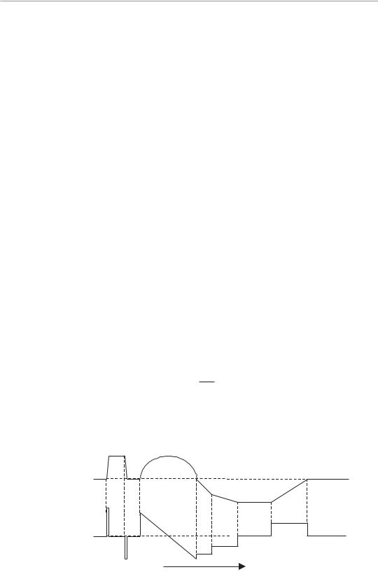
Figure 16.8 shows a changing measured variable and the resulting proportional and derivative waveforms. To obtain the control signal, the proportional and derivative waveforms are added, as shown in the composite waveform.
Figure 16.9 shows the effect of PD action on the correction time. When a change in loading is sensed, both the P and D signals are generated and added, as shown. The effect of combining these two signals is to produce a signal that speeds up the actuator’s control signal. The faster reaction time of the control signal reduces the time to implement corrective action, thus reducing the excursion of the measured variable and its settling time. The amplitudes of these signals must be adjusted for optimum operation, otherwise, overshoot or undershoot can still occur.
In derivative controller action, the derivative of the error is the rate at which the error is changing, and is approximately given by:
where the gain KD is the percentage change in controller output for every percentage per second rate of change of error.
Change in variable
Derivative of variable
Time
Figure 16.7 Variable change and resulting derivative waveform.
16.4 Continuous Control |
279 |
Change in variable
Proportional signal
Derivative signal
|
Derivative |
|
response |
Signal to |
|
|
|
|
actuator |
Portional |
|
response |
Time
Figure 16.8 Generation of proportional plus derivative waveform for actuator control.
Change |
Measured variable change |
in load |
Derivative change
Controlled |
|
variable |
|
change |
Proportional only |
|
Proportional + derivative
Measured variable change
Time
Figure 16.9 Proportional plus derivative control action.
Note that an output is obtained only when the error is changing.
In PD action, the analytic expression is given by the combination of (16.1) and (16.3), and is given by:

280 Process Control
p = K |
e |
|
+ K |
K |
|
dep |
+ p |
|
(16.4) |
|
|
|
|
p |
|
p |
p |
|
D dt |
o |
|
16.4.3Integral Action
Proportional plus integral (PI) action, also known as reset action, was developed to correct for long-term loads, and applies a correction that is proportional to the area under the change in the variable curve. Figure 16.10 gives some examples of the integration of a curve or the area under a curve. In the top example, the area under the square wave increases rapidly but remains constant when the square wave drops back to zero. The area increases more rapidly when the sine wave is at its maximum, and more slowly as it approaches the zero level. During the triangular section, the area decreases rapidly at the higher slopes, but increases slowly as the triangle slope reduces, as shown. Integral action gives a slower response to changes in the measured variable to avoid overshoot, but has a high gain, so that with long term load changes, it takes over control of the manipulated variable, and applies the correction signal to the actuator. Because of the higher gain, the measured variable error or offset is reduced to close to zero. This also returns the proportional amplifier to its normal operating point, so that it can correct other fluctuations in the measured variable. Note that these corrections are done at relatively high speeds, while the older pneumatic systems are much slower, and can take several seconds to make such a correction. When a change in loading occurs, the P signal responds to take corrective action to restore the measured variable to its set point. Simultaneously, the integral signal starts to change linearly to supply the long-term correction, thus allowing the proportional signal to return to its normal operating point. The integral signal can become complex. The expression for the integral process is given by:
p(t) = KI ∫0tep dt + p(0) |
(16.5) |
where p(0) is the controller output when the integral action starts, and the gain KI is the controller output in percentage needed for every percentage time accumulation of error.
Alternatively the integral action can be found by taking the derivative of (16.5), which gives:
Change in variable
Integral of variable
Time
Figure 16.10 Integral variable change in response to a change in a variable, and in the area under the change in a variable.

16.4 Continuous Control |
281 |
Equation 16.4 shows that if the error is not zero, then the output will change at a rate of KI% per second for every 1% of error. The integral of a function determines the area under the function, so (16.4) is providing a controller output equal to the error under the error-time curve, multiplied by KI. For every 1% second of accumulated error-time area, the output will be KI%.
When proportional mode is combined with integral mode, the equation for the control process is given by combining (16.1) and (16.5), to give:
p = Kp ep + Kp KI ∫0tep dt + pI (0) |
(16.7) |
where pI(0) is the integral term value at t = 0 (initial value).
16.4.4PID Action
A combination of all three of the actions described above is more commonly referred to as PID action. The waveforms of PID action are illustrated in Figure 16.11. The proportional, derivative, and integral signals are generated from the change in measured variable. The P and D signals are summed, and combined with the I signal, to generate the PID signal for the controlled variable. The integral signal
Change |
Measured variable change |
in load |
Derivative change
Integral change
P + D
PID
Measured variable after correction
Time
Figure 16.11 (a) Waveforms for proportional plus integral action, and (b) waveforms for proportional plus derivative and integral action.
is shown taking over from the proportional signal and reducing the offset to zero. PID is the most complex corrective action used for process control. However, there are many other types of control actions based upon PID action. Understanding the fundamentals of PID action gives a good foundation for understanding other types of controllers. The waveforms have been idealized for ease of explanation, and are only an example of what may be encountered in practice. Loading is a function of demand, and is not affected by the control functions or actions. The control function is to ensure that the variables are within their specified limits.
The effects of combining P, I, and D, can be found by combining (16.4) and (16.7) the typical PID equation is as follows:
p = Kp ep |
+ Kp KD |
dep |
+ kp KI ∫0tep dt + pI (0) |
(16.8) |
|
|
|
dt |
|
Where p is the controller output in percentage of full scale, ep is the process error in percentage of the maximum, Kp is the proportional gain, K1 is the integral gain, KD is the derivative gain, and p1(0) is the internal controller integral output.
This equation can be implemented using op-amps. An alternative expression when combining the effects of P, I, and D is give by:
|
1 |
t |
|
de |
|
Output α gain e + |
|
edt + T |
|
|
|
(16.9) |
T |
|
|
|
∫0 |
d |
dt |
|
|
1 |
|
|
|
|
|
where, Output is the controller output, e is the error (variable – set point), Ti is integral time in minutes, t = time (minutes), and Td is the derivative time in minutes.
To give an approximate indication of the use of PID controllers for different types of loops, the following are general rules:
•Pressure control requires P and I, but D is not normally required.
•Level control uses P and sometimes I, but D is not normally required.
•Flow control requires P and I, but D is not normally required.
•Temperature control uses P, I, and D, usually with I set for a long time period.
However, these are general rules, and each application has its own requirements.
Typical feedback loops have been discussed. However, the reader should be aware that there are other kinds of control loops used in process control, such as cascade, ratio, and feed-forward controls.
Cascade control is two feedback loops operating together in a series mode. The interaction that occurs between two control systems can sometimes be used to achieve an overall improvement in performance. This could be achieved in a feedback loop by measuring a second variable to give enhanced control. An example of cascade control is shown in Figure 16.12. The primary controller measures the temperature of the fluid and adjusts the fuel flow into the heater to control the temperature. A secondary control loop is introduced to measure the rate of flow of fuel. The primary controller now adjusts the set point of the secondary loop to give improved fuel flow and better temperature control.

16.4 Continuous Control |
283 |
Cold |
|
material |
|
in |
Temperature sensor |
|
|
Hot |
Flow sensor |
material |
|
out |
Fuel |
|
Primary controller |
Set point |
Secondary controller
Set point to 2nd controller
Figure 16.12 Cascade feedback loop.
Ratio control is used to reference one variable to another variable. An example of this is shown in Figure 16.13, where a controlled flow rate is set to a primary flow rate by a fixed ratio. The primary flow rate is measured and the ratio is used as the set point to the controller, setting the secondary flow rate. The primary flow rate (wild flow) is uncontrolled, and can be used as a reference to control several other variables.
Feed-forward control is used to anticipate a change and on its own is an open loop control, but is normally used in conjunction with a feedback control system. In Figure 16.14, the flow sensor is used to detect the increase (or decrease) in the rate of material flow, which will eventually lead to a temperature drop in the measured variable. The flow sensor will increase the fuel to the heater in anticipation that the temperature of the material is going to drop, because of the increase in demand. The change in flow rate can be sensed before the actual temperature drops, because of
Primary flow
DP
DP
Controlled flow primary flow x ratio
Figure 16.13 Ratio control loop.

|
284 |
|
Process Control |
|
Cold |
|
|
|
material |
|
|
|
in |
Temperature sensor |
|
|
|
|
|
|
|
Hot |
|
Fuel |
DP |
material |
|
out |
|
|
|
|
|
Controller |
|
|
|
Set point |
Figure 16.14 Feed-forward feedback loop.
the reservoir of hot material in the heater. The feedback loop can then fine-tune the amount of fuel required to maintain constant temperature.
16.4.5Stability
In a closed loop feedback system, settings are critical. If the system has too much gain and/or is underdamped, then the amplitude of the correction signal is too great and/or changing too rapidly. This can cause the controlled variable to overcorrect for the error, which can cause the system to become unstable and oscillate, or can cause an excessively long settling or lag time. If the gain in the system is too low or overdamped, then the correction signal is too small or slow, and the correction never will be fully completed, or an excessive amount of time will be taken for the output to reach the set reference level.
This effect, as shown in Figure 16.15, can be seen in comparing the overcorrected (excessive gain) or underdamped, and the undercorrected (too little gain) or overdamped to the optimum gain case (with just a little overshoot) and correct damping. It takes a much longer time for the variable to implement the
Input
Stable over damped
under corrected
Output
Input
Input
Unstable |
Output |
under damped |
Figure 16.15 Effect of loop gain and damping on correction time using proportional action, with overcorrection and undercorrection.


