

5.8. POLYPHASE AC POWER |
457 |
5.8.4 Symmetrical components
Balanced three-phase networks are relatively easy to calculate quantities in, as each line and phase variable is symmetrical. For instance, if we happen to know one of the phase voltages in a balanced Wye-connected power system component is 2400 volts, then we may safely conclude the other two
phase voltages are |
2400 volts as well. The voltage between any two lines in this same system is |
|||
√ |
|
√ |
|
|
guaranteed to be |
3 larger than any phase voltage: 2400 3 ≈ 4160 volts. |
|||
Calculations become much more complex, however, in unbalanced three-phase networks. One of
√
the assumptions we must discard in an unbalanced network is the simple factor of 3 relating phase
√
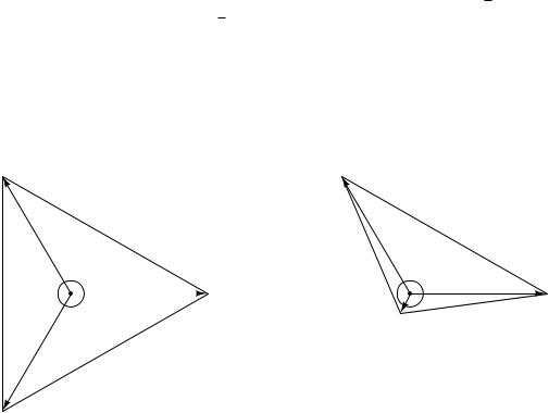
and line quantities: while Vline = Vphase 3 in a balanced Wye-connected system, it is not necessarily true in an unbalanced Wye-connected system. Compare these phasor diagrams of a balanced versus unbalanced 2400/4160 volt Wye systems, the unbalanced system being representative of a three-phase generator with a fault in one of the phase windings causing that phase voltage to be substantially less than it ought to be:
Balanced Wye-connected system
C
|
|
V |
|
|
V |
|
|
|
|
|||
|
|
|
|
= |
|
|
|
AC |
= |
|
|
|
|
|
|
C |
|
|
|
|
|
4160 |
|
|
|
|
|
|
|
2400 |
|
|
|
V |
||||
V |
|
|
|
|
V |
|
|
|
|
|
|
|
4160 |
|
|
|
|
|
|
|
o |
|
|
|
|
|
|
|
|
|
|
|
120 |
VA = 2400 V |
||||
|
|
|
|
|
|
o |
|
|
||||
= |
|
|
|
120 |
|
|
|
|
|
A |
||
|
|
|
|
120 |
|
|
|
|||||
|
|
|
|
|
|
|
|
|
|
|||
BC |
|
|
|
|
V |
|
|
|
|
|
||
|
|
|
2400 |
|
|
o |
|
|
|
|
||
V |
|
|
|
|
|
|
|
|
V |
|||
|
V |
B |
= |
|
|
|
|
|
4160 |
|
|
|
|
|
|
|
|
|
|
|
|
||||
|
|
|
|
|
= |
|
|
|
||||
|
|
|
|
|
|
|
|
|
||||
|
|
|
|
|
|
|
VAB |
|
|
|
|
|
B
Unbalanced Wye-connected system
(phase B voltage 1/10 of other phases)
C |
|
|
|
|
|
|
|
|
V |
|
|
V |
|
|
|
V |
= |
|
|
AC = |
|
|
|
|
C |
|
|
|
|
4160 |
|
BC |
|
|
|
|
|
V |
|
= |
|
|
|
|
|
||
|
2400 |
|
|
|
|
|
|
2530 |
V |
|
|
|
|
||
|
|
120 |
|
|
|
||
|
|
|
|
o |
|
|
|
|
|
120 |
o |
|
VA = 2400 V |
||
|
V |
|
120 o |
|
|
A |
|
|
|
|
|
|
|||
|
|
|
|
|
|
|
|
B |
VAB = 2530 V |
|
|
|
|
240 |
V |
|
|
= |
|
|
V |
B |
|
|
|
|
|
|
||
|
|
|
|
In fact, the existence of faults in three-phase power systems is the primary reason for considering unbalanced systems, since the vast majority of three-phase electrical components are expressly designed to be balanced. If power system engineers and technicians are to analyze faults, they must have some means of quantifying unbalanced system conditions.
A breakthrough in mathematical analysis for unbalanced three-phase electrical circuits came in 1913 from a man named Charles Legeyt Fortescue, who presented his discovery in a paper entitled, “Method of Symmetrical Co-ordinates Applied to the Solution of Polyphase Networks” after doing research on AC induction motors operating under unbalanced conditions. His discovery condenses to the fact that any set of phasors describing conditions of voltage or current in a three-phase network, no matter how unbalanced and asymmetrical they may be, are mathematically equivalent to the sum of three unique phasor sets with di erent rotations. Thus, it is possible to mathematically decompose an unbalanced phasor triad into a multiple sets of balanced phasor triads, each of those
458 |
CHAPTER 5. AC ELECTRICITY |
balanced sets being relatively easy to analyze on its own because the simple rules of symmetrical
√
networks (e.g. the 3 factor between phase and line quantities) still apply.
Fortescue’s breakthrough is reminiscent of Jean Baptiste Joseph Fourier’s discovery roughly 100 years prior that any periodic waveform, no matter its shape, is mathematically equivalent to a summation of pure sinusoidal waveforms of harmonic frequencies (called a Fourier Series). In both cases, we see there is a mathematical equivalence between one entity that is ugly and asymmetrical, and a set of pure and symmetrical entities that are easier to deal with on mathematical terms.
In Fortescue’s model, which is widely known under the title of symmetrical components, any set of three phasors describing voltage or current in a three-phase system is equivalent to the summation of three di erent three-phasor sets:
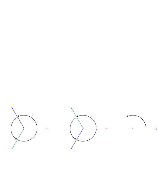
•One set of three phasors rotating in the normal A-B-C direction of the power system, called the positive sequence. By convention, this sequence is designated by the number 1.
•One set of three phasors rotating in the reverse direction (A-C-B)46, called the negative sequence. By convention, this sequence is designated by the number 2.
•One set of three phasors all pointed in the same direction, having no sequence at all, called the zero sequence. By convention, this sequence is designated by the number 0.
Positive sequence |
Negative sequence |
Zero sequence |
(A-B-C rotation) |
(A-C-B rotation) |
(in-phase rotation) |
C1 |
B2 |
|
|
o |
|
|
o |
|
|
|
120 |
|
|
120 |
|
|
B0 |
|
120o |
|
A1 |
120o |
|
A2 |
|
A0 |
|
|
|
|||||
120 |
|
|
120 |
|
|
C0 |
|
|
o |
|
|
o |
|
|
|
B1 |
C2 |
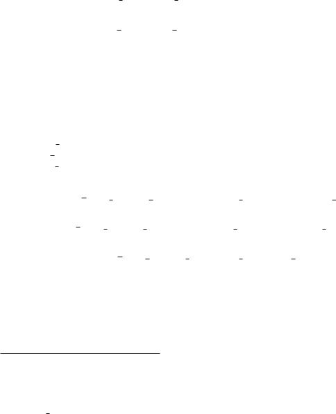
Fortescue’s discovery was that we may synthesize any possible three-phasor set simply by superimposing these positive, negative, and/or zero sequence phasor sets at the appropriate magnitudes and phase shifts. Each positive sequence, negative sequence, and zero sequence set is perfectly balanced, although they must usually di er in magnitude from each other in order for the summation of all three to equal the real-world unbalanced set.
46If you are having di culty seeing the A-B-C or A-C-B rotations of the positive and negative sequences, you may be incorrectly visualizing them. Remember that the phasors (arrows) themselves are rotating about the center point, and you (the observer) are stationary. If you imagine yourself standing where the tip of each “A” phasor now points, then imagine all the phasor arrows rotating counter-clockwise, you will see each phasor tip pass by your vantage point in the correct order.
5.8. POLYPHASE AC POWER |
459 |
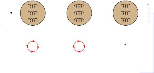
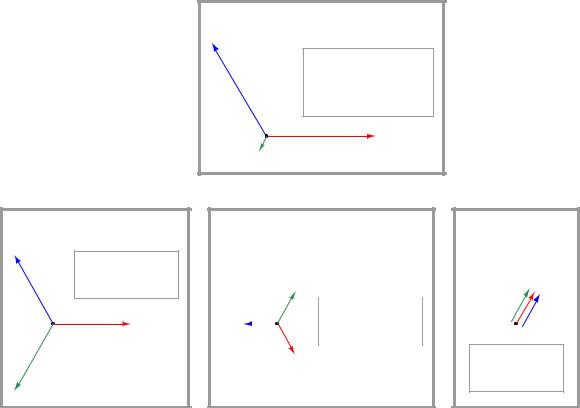
Another way of stating this is to say that the actual voltages and currents in a three-phase power system, no matter how unbalanced they may be from each other, are really equivalent to multiple sets of voltages and currents existing in the circuit simultaneously, each with its own rotational sequence and perfectly balanced magnitude. Our hypothetical three-phase generator with the faulted phase winding, therefore, is really equivalent to three healthy generators with their windings wired together to be series-aiding: one generator spinning in the normal direction, the next generator spinning the wrong direction, and the last generator a single-phase unit with three in-phase windings. The combined sum of these three generators’ outputs would create the exact same patterns of voltages and currents as the one faulted-winding generator:
|
|
|
|
|
Positive sequence |
Negative sequence |
Zero sequence |
||||||
|
|
|
|
|
generator |
generator |
generator |
||||||
|
|
|
|
|
|
|
|
|
|
|
|
|
|
|
|
|
|
|
|
|
|
|
|
|
|
|
|
|
|
|
|
|
|
|
|
|
|
|
|
|
|
|
|
|
|
|
|
|
|
|
|
|
|
|
|
|
|
|
|
|
|
|
|
|
|
|
|
|
|
3-phase generator |
3-phase generator |
1-phase generator |
spinning forward |
spinning backward |
(no phase sequence) |
(rotation = ABC) |
(rotation = CBA) |
|
Any unbalanced phase pattern imaginable may be produced by combining the proper positive, negative, and zero sequence phasor sets from these three generators!
460 |
CHAPTER 5. AC ELECTRICITY |
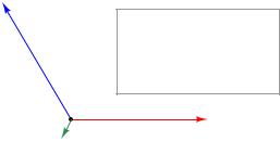
Let us explore this in more detail by means of a concrete example. Taking the faulted-winding generator whose phasor voltage diagram was shown earlier (phase voltages VA and VC at 2400 volts each, but phase voltage VB at only 240 volts), our task is to see how to decompose this unbalanced set of voltage phasors into three balanced sets of phasors (positive-, negative-, and zero-sequence):
Voltage phasor diagram for faulted generator
C
VA = 2400 V Ð 0o
VB = 240 V Ð 240o
VC = 2400 V Ð 120o
A
B
Somehow, we must determine the specific pattern of balanced positive-, negative-, and zerosequence phasor sets that will be equivalent to the unbalanced phasor set describing our faulted generator. Once we determine these symmetrical components, we will then sum them together to demonstrate how the respective phasors do indeed add up to the original (unbalanced) phasor diagram.
5.8. POLYPHASE AC POWER |
461 |
Thankfully, symmetrical component analysis provides us with a set of equations for calculating the “A” phasor of each sequence47. Please note that each variable in each of the following equations is a phasor quantity, possessing both a magnitude and a phase angle. Also note that these equations apply just as well to calculations of current as they do to voltage:
Va1 = |
1 |
(Va |
+ Vb6 |
+ 120o + Vc6 |
+ 240o) |
Positive-sequence phasor A |
|||||||
|
|
|
|
||||||||||
|
|
3 |
|||||||||||
Va2 = |
1 |
(Va + Vb6 |
|
+ 240o + Vc6 |
+ 120o) |
Negative-sequence phasor A |
|||||||
|
|
|
|||||||||||
|
3 |
||||||||||||
|
Va0 = |
1 |
(Va |
+ Vb + Vc) |
Zero-sequence phasor A |
||||||||
|
|
|
|||||||||||
|
|
3 |
|||||||||||
The “+120o” and “+240o” references deserve further explanation48. What we are saying here is that the calculations involve shifting the angle of the unbalanced system’s phasor by either +120 degrees or +240 degrees when calculating the phasors for the positive and negative sequences. Performing the calculations:
Given phasors in unbalanced system:
Va = 24006 0o
Vb = 2406 240o
Vc = 24006 120o
Va1 = 13 [24006 0o + 2406 (240o + 120o) + 24006 (120o + 240o)] = 16806 0o
Va2 = 13 [24006 0o + 2406 (240o + 240o) + 24006 (120o + 120o)] = 7206 − 60o
Va0 = 13 [24006 0o + 2406 240o + 24006 120o] = 7206 60o
Recalling that our faulted generator is mathematically equivalent to three healthy generators with their respective phase windings connected in series, these solutions tell us that the equivalence is one generator spinning the correct direction at 1680 volts per phase, connected to another generator spinning the wrong direction as well as phase-shifted −60 degrees at 720 volts per phase, connected to a single-phase generator phase-shifted +60 degrees at 720 volts per phase. These three healthy generators, each one producing a symmetrical (balanced) set of voltages, will together behave the same as our one 2400 volt phase generator with the faulted “B” winding.
47It is good to remember that each of the symmetrical components is perfectly balanced (i.e. the “b” and “c” phasors each have exactly the same magnitude as the “a” phasor in each sequential set), and as such each of the phasors for each symmetrical set will have exactly the same magnitude. It is common to denote the calculated phasors simply as V1, V2, and V0 rather than Va1, Va2, and Va0, the “a” phasor implied as the representative of each symmetrical component.
48A “shorthand” notation commonly seen in symmetrical component analysis is the use of a unit phasor called a, equal to 16120o. Multiplying any phasor quantity by a shifts that phasor’s phase angle by +120 degrees while leaving its magnitude una ected. Multiplying any phasor quantity by a2 shifts that phasor’s phase angle by +240 degrees while leaving its magnitude una ected. An example of this “a” notation is seen in the following formula for calculating the positive sequence voltage phasor: Va1 = 13 (Va + aVb + a2Vc)
462 |
CHAPTER 5. AC ELECTRICITY |
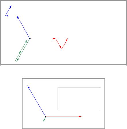
Graphically, the decomposition of the original unbalanced phasor diagram into symmetrical components is as follows:
Positive sequence |
|
phasor diagram |
|
C1 |
VA1 = 1680 V Ð 0o |
|
|
|
VB1 = 1680 V Ð 240o |
1680 |
VC1 = 1680 V Ð 120o |
|
|
V |
|
|
1680 V |
|
A1 |
1680 |
V |
|
|
B1 |
|
Voltage phasor diagram for |
|
|
C |
faulted generator |
|
|
|
|
|
VA = 2400 V Ð 0o |
|
2400 |
VB = 240 V Ð 240 |
o |
|
||
|
|
|
V |
VC = 2400 V Ð 120o |
|
|
2400 V |
|
|
A |
|
B |
240 V |
|
Negative sequence phasor diagram
B2
|
|
720 |
V |
|
|
||
720 V |
VA2 |
= 720 V Ð -60o |
|||||
|
|||||||
|
|
|
|||||
|
|
|
VB2 = 720 V Ð 60o |
||||
C2 |
|
|
|
||||
|
|
|
|
|
|||
720 |
VC2 |
= 720 V Ð 180o |
|
V |
|||
|
|
||
A2 |
|
|
Zero sequence phasor diagram
B0 A0
|
V |
C0 |
720 |
|
|
|
|
VA0 = 720 V Ð 60o VB0 = 720 V Ð 60o VC0 = 720 V Ð 60o
5.8. POLYPHASE AC POWER |
463 |
The graphical proof that these three symmetrical component phasor sets do indeed add up to be equivalent to the original (unbalanced) phasor diagram of the faulted generator is as follows:
Summation of symmetrical phasor sets (+, -, and 0 sequences)
720 |
V |
C0 |
|
C2 |
720 V
1680
VA = VA1 + VA2 + VA0 = 1680Ð0o + 720Ð-60o + 720Ð60o VB = VB1 + VB2 + VB0 = 1680Ð240o + 720Ð60o + 720Ð60o
VC = VC1 + VC2 + VC0 = 1680Ð120o + 720Ð180o + 720Ð60o
C1
V
B0
720
B2 |
720 |
V |
|
||
|
|
V
1680
1680 V |
720 |
A1 |
V |
|
A2 |
V
B1
A0
720 |
V |
|
Phasor diagram for (original) faulted generator
C |
|
|
|
VA = 2400 V Ð 0o |
|
2400 |
VB = 240 V Ð 240 |
o |
|
||
|
|
|
V |
VC = 2400 V Ð 120o |
|
|
2400 V |
|
|
A |
|
B |
240 V |
|
464 |
CHAPTER 5. AC ELECTRICITY |
In a perfectly balanced three-phase power system, the only sequence in existence is the positive sequence (1). Any and all measurements of voltage and current, therefore, represent the positive sequence of the system. since the magnitudes of the negativeand zero-sequence components are zero. If an imbalance occurs for any reason – from unbalanced single-phase loads on a three-phase power system to actual faults (opens, shorts) – negative-sequence and/or zero-sequence components arise.
While negative-sequence quantities cannot be measured directly by any voltmeter or ammeter, zero-sequence components can. In Y-connected systems, zero-sequence current manifests itself as current through the neutral conductor, while zero-sequence voltage manifests itself as voltage between the center of an ungrounded Wye and ground. Zero-sequence current manifests in Deltaconnected systems as current circulating in the phase elements of the source or load.
The following illustration shows a medium-voltage (4160 volt) electric motor circuit equipped with a protective relay to halt the motor in the event its electrical or thermal parameters indicate the potential for damage:
|
|
|
"Zero sequence" |
|
|
|
CT |
|
CT |
|
|
|
|
|
|
|
(Bearing) |
|
|
CT |
|
|
|
4160 VAC |
|
|
|
Motor |
RTD |
3-phase |
|
|
|
||
|
|
|
|
||
|
|
|
CT |
|
|
|
|
|
|
RTD |
|
PT |
PT |
|
|
|
(Stator) |
|
|
|
|
||
Line voltage sensing |
|
Line current sensing |
Ground fault sensing |
Temperature sensing |
|
|
Protective relay |
|
|
|
|
|
|
|
Trip contacts |
|
|
Control power in |
Analog signal output |
RS-485 comm |
|
|
|
125 VDC |
|
|
|
Trip coil on circuit breaker |
|
|
|
|
Trip |
|
|
|
|
|
|
|
|
125 VDC
4-20 mA |
Modbus |
Note the “zero sequence” current transformer (CT) encircling all three lines conducting power to the motor. This large CT magnetically senses the instantaneous sum of currents into and out of the motor, which should be zero under normal operating conditions. If, however, a ground fault develops within the motor, the instantaneous sum of currents will become non-zero, causing the “zero sequence CT” to register some current. If this zero-sequence current becomes large enough,
5.8. POLYPHASE AC POWER |
465 |
the protective relay will command the contactor feeding power to the motor to trip (open) in order to protect the motor against further damage.
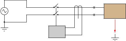
This exact same principle is used in household “GFCI” (Ground Fault Current Interruptor) receptacles and circuit breakers required by the National Electrical Code to be used in “wet” areas of a residence such as bathrooms: a small current transformer senses the net sum of current through the “hot” and “neutral” conductors. If this net current measurement is anything but zero, the interruptor contacts trip, ceasing the flow of power to the load and thereby protecting the person using that load from injury due to ground-fault current passing through their body:
Ground-Fault Current Interruptor (GFCI)
|
Interrupting |
Hair dryer, toaster, etc. |
|
|
contacts |
||
Hot |
CT |
||
|
|||
120 VAC |
|
120 VAC |
|
|
load |
||
|
|
||
Neutral |
|
|
|
|
Trip |
|
|
|
circuit |
|
Any current leaking from the load to earth ground is sensed as an imbalance of current by the CT