

5.8. POLYPHASE AC POWER |
439 |
5.8Polyphase AC power
“Polyphase” means “many phases,” describing a form of AC electrical system where multiple sinusoidal voltages exist that are not in step with each other. The most common form of polyphase AC power in industry is three-phase, but all polyphase systems share similar traits. A good way to understand three-phase AC systems is to begin with an understanding of simpler, single-phase systems.
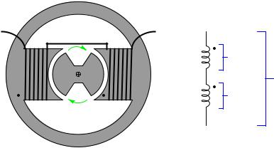
A simple alternator (AC generator) is nothing more than a magnetized rotor spinning between a pair of electromagnetic poles, the stationary wire coils (“stator windings”) developing AC voltage as the spinning rotor’s magnet passes by:
Mechanical
diagram
iron |
Schematic |
|
diagram |
||
|
|
|
60 V |
N |
S |
120 V |
|
|
|
|
|
60 V |
Note that the stator is comprised of two windings connected in series-aiding fashion, so that their respective AC voltages directly add. If each winding of this machine develops 60 volts, the series pair will develop 120 volts. This machine is properly called a single-phase alternator, because all its stator winding voltages are in-phase with each other.
440 |
CHAPTER 5. AC ELECTRICITY |
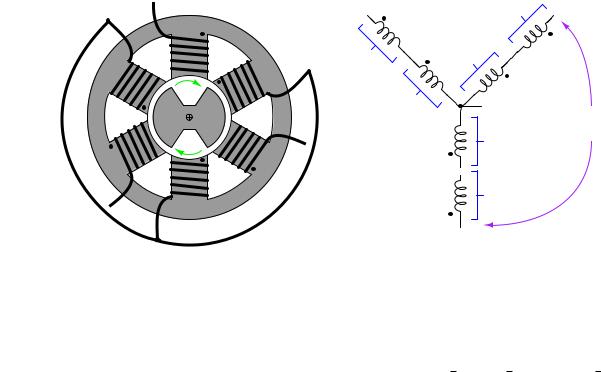
A much more common alternator design uses three sets of stator poles, each one with its own winding pair, to generate three AC voltages phase-shifted from one another by 120o. The reason these three AC voltages are not in-phase with each other is precisely because the three stator poles are not physically aligned with each other, which means the magnetic poles of the spinning rotor will pass by each stator pole pair at di erent times:
Mechanical |
Schematic |
|
diagram |
diagram 60 V |
|
A |
B |
|
A |
|
|
60 V |
60 V |
B |
|
|
C |
|
|
N |
60 V |
Neutral |
S |
208 V |
|
|
|
|
|
|
60 V |
C |
B |
|
|
A |
60 V |
|
|
|
Neutral |
|
C |
|
|
Note that each pair of stator winding voltages directly add, because they are in phase with each other. In the example shown, each individual stator winding develops 60 volts, with each seriesaiding pair (each “phase” of the alternator) developing 120 volts. However, the voltage appearing between di erent stator winding pairs is neither the simple sum (120 + 120) nor the simple di erence (120 − 120) of each phase voltage. Rather, the phase-to-phase voltage is the trigonometric sum of two phasor quantities, spaced 120o apart. In the example shown, 1206 0o + 1206 120o = 207.856 60o, which is approximately 208 volts. This machine is properly called a three-phase alternator. More specifically, this alternator is one with a wye-connected stator winding set, because the geometric configuration of the stator windings resembles that of the letter “Y”.
5.8. POLYPHASE AC POWER |
441 |
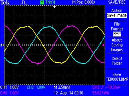
The following oscilloscope screenshot shows the output of a three-phase alternator, each channel of the oscilloscope connected across one phase of the alternator (e.g. Channel 1 across “A” and Neutral, Channel 2 across “B” and Neutral, and Channel 3 across “C” and Neutral):
In this oscillograph image we can clearly see a 120o phase shift between successive phase voltage waveforms. From this image we may also discern the phase sequence or phase rotation of the system: the sequential order in which the three phases reach their respective peak values. Phase sequence is determined by the direction of the alternator shaft’s rotation as well as the orientation of the stator phase windings. Surveying the three sine waves from left to right (the forward direction of time) on the oscillograph, we see channel 1 (Yellow) reaches its positive peak 120 degrees before channel 2 (Blue), which reaches its positive peak 120 degrees before channel 3 (Magenta). A common method of describing phase rotation is to list the phase letter labels in their order of sequence over time, in this case the triad ABC. It should be noted that a phase sequence of ABC is synonymous with BCA and also with CAB. This is easy to see if we write the letters in sequence for several rotations of the alternator, seeing that all three triads may be found within the longer sequence: ABCABCABCABC.
442 |
CHAPTER 5. AC ELECTRICITY |
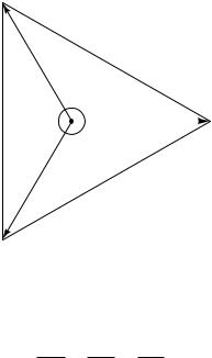
This trigonometric relationship between voltages in this “wye” connected alternator is clearly shown in the following phasor diagram. Solid phasors express the phase voltage for each of the three winding pairs in a three-phase alternator, while dashed lines express the line voltage between any two of the three output terminals on the alternator. The direction of each phasor expresses its phase shift in time, as the sine wave voltages produced by each of the three phase windings will be shifted apart from each other by 120 degrees. Here, each phase winding in the alternator happens to produce 120 VAC, resulting in a line voltage equal to the trigonometric sum of the 120 VAC phasors, 208 VAC:
Voltage phasor diagram for a wye-connected alternator
C
BC
V = 208 V
|
|
|
|
|
V |
|
|
|
|
|
|
|
|
|
|
|
CA |
|
|
|
|
|
|
|
V |
= |
208 |
|
|
|||
|
|
|
|
|
|
|
|
|||
|
|
|
C |
|
|
|
|
|
||
|
|
|
|
|
|
|
|
|
||
|
|
|
|
= |
|
|
|
|
V |
|
|
|
|
|
120 |
|
|
|
|
||
|
|
|
|
V |
|
|
|
|
|
|
|
|
|
|
|
|
o |
|
|
|
|
|
|
|
|
|
120 |
VA = 120 V |
||||
|
|
|
|
120o |
|
|
||||
|
|
|
|
|
|
|
|
|
A |
|
|
|
|
|
120 |
|
|
|
|||
|
|
|
|
|
|
|
|
|
||
|
|
|
|
V |
|
o |
|
|
|
|
|
|
|
120 |
|
|
|
|
|
|
|
|
|
= |
|
|
|
|
|
V |
||
|
B |
|
|
|
|
|
|
|||
V |
|
|
|
|
|
208 |
|
|||
|
|
|
|
|
|
|
||||
|
|
|
= |
|
|
|||||
|
|
|
|
|
|
|||||
|
|
|
|
|
|
|
||||
|
|
|
|
|
|
VAB |
|
|
|
|
B
A simple way to calculate the side lengths of these non-right triangles is to use the Law of Sines, which simply states the ratio between the length of a triangle’s side and the sine of its opposite angle is constant, for any triangle:
sin a = sin b = sin c A B C
Applying this to the solution of the voltage between phases A and B (120 volts each, individually):
sin 120o |
= |
sin 30o |
= |
sin 30o |
|
||||||||
|
VAB |
|
|
VA |
|
|
|
VB |
|
|
|||
|
sin 120o |
= |
|
sin 30o |
|
|
|||||||
|
|
VAB |
120 volts |
|
|
|
|||||||
|
|
|
|
|
|||||||||
|
|
|
|
|
|
|
|
sin 120o |
|
||||
VAB = (120 volts) |
|
||||||||||||
sin 30o |
|||||||||||||
VAB = 207.84 volts ≈ 208 volts
5.8. POLYPHASE AC POWER |
443 |
|||
sin 120o |
√ |
|
|
|
3), and this factor frequently appears in |
||||
The ratio sin 30o is equal to the square-root of three ( |
|
|||
three-phase electrical system calculations. |
|
|
|
|
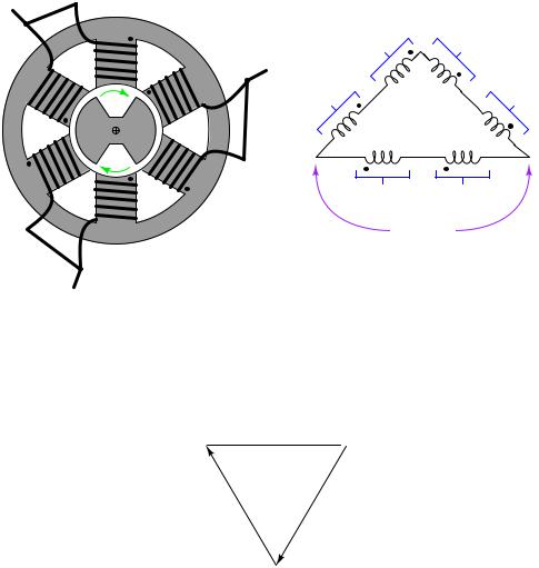
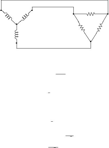
Some three-phase alternators have their phase windings connected di erently, in a “delta” configuration rather than a “wye” configuration:
Mechanical |
Schematic |
diagram |
diagram |
A |
60 V |
60 V |
|
||
B |
C |
60 V |
|
60 V |
|
N |
S |
|
C |
B |
|
|
60 V |
60 V |
A |
|
120 V |
The phasor diagram for voltage in a delta-connected alternator is simpler, because phase voltage is exactly equal to line voltage, with each phase coil directly connected to a pair of line terminals:
Voltage phasor diagram for a delta-connected alternator
VCA = 120 V
C  A
A
VA = 120 V
V |
V |
|
C |
BC |
= |
= |
120 |
|
V |
120 |
|
|
V |
|
|
|
120 |
|
V |
|
|
120 |
V |
|
|
|
|
|
|
|
|||
|
B |
= |
|
|
|
|
|
||
V |
|
|
|
|
= |
|
|||
|
|
|
|
|
|
|
|||
|
|
|
|
|
AB |
|
|
||
|
|
|
|
V |
|
|
|
|
|
|
|
|
|
|
|
|
|
|
B
444 |
CHAPTER 5. AC ELECTRICITY |
The following photograph shows the terminal connections on the rear side of a three-phase alternator intended to provide electrical power on a heavy-duty truck or boat. Note the three power terminals at the bottom of the photograph (with yellow-colored wire connectors attached), where the three-phase AC power is output. Also note the two copper “slip rings” I am pointing to with my finger, where DC power is conducted through stationary carbon “brushes,” through the copper rings on the shaft, to a winding on the spinning rotor to control its magnetization. The shaft of this alternator, normally coupled to the crankshaft of the vehicle’s engine by a V-belt, is on the far side of the alternator hidden from view of the camera:
Larger alternator units, such as those found in power plants, do not di er substantially in design from this small unit. Sets of stator windings around the circumference of the machine connected in either a wye or a delta configuration generate three-phase AC power, while a magnetized rotor spins at the center of the machine providing the changing magnetic field necessary to induce voltage in those stator windings. Permanent-magnet rotors are seldom used because they o er no way to control or regulate the machine’s output voltage during operation. Instead, the rotor has a single winding of its own, energized by DC supplied externally by a voltage regulator circuit. If more AC voltage is desired from the alternator, the regulator circuit sends more direct current to the rotor in order to strengthen its magnetic field. If less AC voltage is desired, the regulator sends less current to the rotor’s winding in order to weaken its magnetic field.
5.8. POLYPHASE AC POWER |
445 |
One of the advantages of three-phase AC power over single-phase AC power is a more constant delivery of electrical energy to the load over time. With three sets of stator windings at work, the combined e ect is not unlike a triple bicycle with the three riders’ legs staggered by 120o of rotation, or of a multi-cylinder automobile engine with the pistons staggered apart from each other: at any given time, at least one of the phases will be at or near its peak. Single-phase AC systems, by contrast, pulsate to a much greater extent.
In a single-phase AC circuit, energy transfer actually stops completely twice per cycle, when the current waveform passes through zero. This never happens in a polyphase system, because there are always other phases at non-zero current values when any one phase is at its zero-crossing point, owing to the fact that the phases in a polyphase power system are shifted from one another. This fact results in more e cient transfer of energy in AC power systems: a three-phase power system can actually transfer the same amount of power as a comparable single-phase power system using less metal in the power line conductors, despite the fact that a greater number of conductors is necessary (3 versus 2).
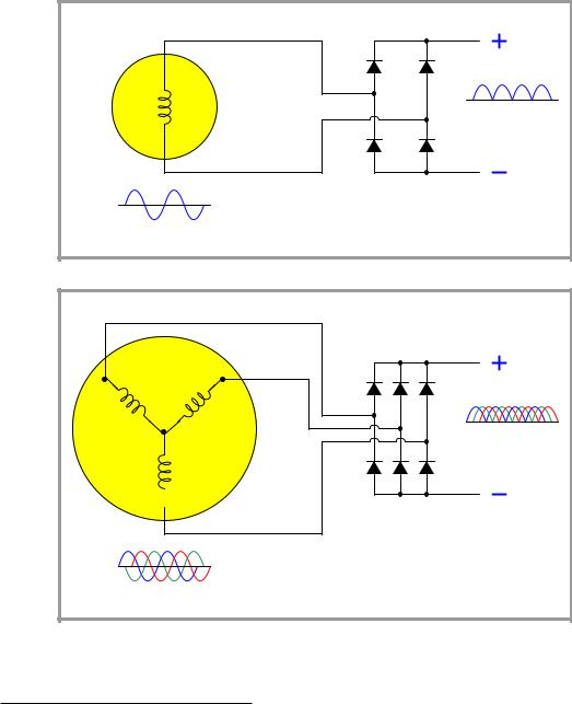
Another advantage of three-phase AC power is in applications where the AC is to be rectified into DC. The rectified output of a three-phase alternator is “smoother” than the rectified output of a single-phase alternator, with less ripple voltage to interfere with on-board electronic devices such as radios, because the phase-shifted currents overlap each other. This is why all automotive alternators are three-phase rather than single-phase machines.
446 |
CHAPTER 5. AC ELECTRICITY |
A comparison of single-phase rectification versus three-phase rectification shows this clearly:
Single-phase alternator |
Single-phase rectifier |
|
Rectified DC |
Single-phase AC |
|
Three-phase alternator |
|
Three-phase rectifier
A
B
Rectified DC
C 
Three-phase AC (ABC phase sequence)
Not only is the ripple of the rectified DC voltage less in a three-phase system than in a singlephase system, but the frequency of that ripple is three times as great, making it easier to filter41 out of the DC power.
41Low-pass filter circuits are typically used to “smooth” the ripple from the output of a rectifier. The greater the frequency of this ripple voltage, the easier it is to filter from the DC (which has a frequency of zero). All other factors being equal, a low-pass filter attenuates higher-frequency components to a greater extent than lower-frequency components.
5.8. POLYPHASE AC POWER |
447 |
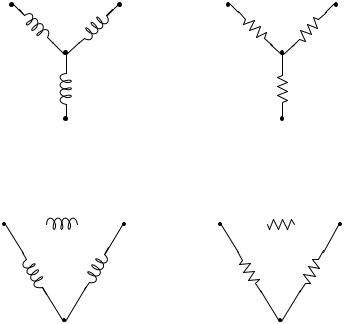
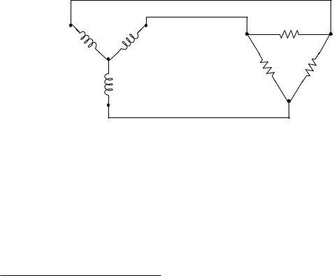
5.8.1Delta and Wye configurations
Two basic forms of three-phase sources and loads appearing in industrial power systems are the delta
(Δ) and the wye (or simply Y ) configurations. A “wye-connected” device has its three elements joined at one common point in the middle as such:
Wye-connected |
Wye-connected |
motor or generator |
resistive load |
By contrast, a “delta-connected” device has its three elements joined as the sides of a triangle:
Delta-connected |
Delta-connected |
|||||
motor or generator |
resistive load |
|||||
|
|
|
|
|
|
|
Each configuration has its own unique advantages and disadvantages in the larger context of a three-phase electrical power system. Either source type may connect to either load type (e.g. delta to wye, delta to delta, wye to delta, wye to wye) so long as the voltage and current ratings of all components are compatible.

448 |
CHAPTER 5. AC ELECTRICITY |
The voltage appearing across the terminals of each element in a polyphase device is called the phase voltage, and the current through each element in a polyphase device is called the phase current:
Iphase
Vphase  Iphase
Vphase
Voltage appearing between any two of the connecting conductors (power lines) is called the line voltage of the polyphase system, and current through any of the connecting conductors (power lines) is called the line current:
Iline
 Vline
Vline
Vline
Iline
Line and phase quantities relate to each other di erently between delta devices and wye devices.
√
Line voltage for a balanced42 wye device exceeds phase voltage by a factor of 3, while line current for a balanced delta device exceeds phase current by the same factor:
System type |
Voltage |
Current |
||||
|
√ |
|
|
|
|
|
Wye (Y) |
Vline = 3 × Vphase |
Iline √= |
|
Iphase |
||
|
||||||
Delta (Δ) |
Vline = Vphase |
Iline = 3 × Iphase |
||||
42Here, the term “balanced” refers to a condition where all phase voltages and currents are symmetrically equal. Unbalanced conditions can and do exist in real polyphase power systems, but the degree of imbalance is usually quite small except in cases of component faults.
5.8. POLYPHASE AC POWER |
449 |
While it may be tempting to simply memorize these mathematical relationships, it is far better to understand why they are so. In a wye-connected device, line current must be equal to phase current because each power line is in series with each (respective) phase element, and we know that series-connected elements must share the same current. Likewise, line voltage must be equal to phase voltage in a delta-connected device because each power line pair connects in parallel fashion to each (respective) phase element, and we know that parallel-connected elements always share the same voltage:
Iline = Iphase |
Vline = Vphase |
because currents are equal in series |
because voltages are equal in parallel |
Iline
Iphase
Vline
Vphase
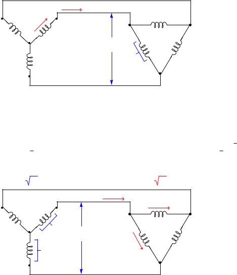
Phase and line voltages are unequal in wye-connected devices, as are phase and line currents in delta-connected devices. In each of these cases, though, we may see once again by visual inspection that these line and phase quantities cannot be equal because the line quantities are the result of two joining phase quantities. In a wye network, line voltage is the series (phasor) sum of two phase voltages. In a delta network, line current is the parallel (phasor) sum of two currents summing at a node. If we know the system in question is balanced, however, we may be assured that√the
multiplying factor between these line and phase quantities will be the square-root of three ( 3),
√ √
therefore line voltage is 3 times greater than wye phase voltage, and line current is 3 times greater than delta phase current:
Vline = 3 Vphase Iline = 3 Iphase
Iline |
Iphase |
|
Vphase Vline
Iphase
Vphase

450 CHAPTER 5. AC ELECTRICITY
As an example of phase and line voltages in a wye-connected system, we see a great many threephase industrial power circuits in the United States of the “480/277” volt configuration. These are a wye-connected devices exhibiting having phase voltages of 277 volts (each) and a balanced line voltage of 480 volts.
In the wye-connected system we see how the two phase voltages add in series (indirectly) to form the larger line voltage. In the delta-connected system we see how the larger line current splits up in parallel branches (indirectly) to form two smaller phase currents. The key to understanding these mathematical relationships is to recognize where the rules of series and parallel connections dictate the quantities be identical or di erent, and then all we√need to remember is that if the two are di erent, the line quantity will be greater by a factor of 3.
5.8. POLYPHASE AC POWER |
451 |
5.8.2Power in three-phase circuits
Suppose we have a 480/277 wye-connected alternator supplying electrical power to a delta-connected load consisting of three 200 ohm resistive heating elements:
480/277 V source |
480 V load |
200 Ω
200 Ω |
200 Ω |
To begin our calculation of all electrical quantities in this circuit, we will apply Ohm’s Law to the calculation of phase current at the load, since we already know phase voltage (480 volts) and phase resistance (200 ohms) there:
480 V
200 Ω
Now that we know phase current at the delta-connected load, we may calculate line current for the whole system by multiplying by the square-root of three:
√
Iline = ( 3)(2.4 A) = 4.157 A
This line current must be the same as the phase current in the wye-connected alternator, since line and phase currents are equal in wye-connected devices by virtue of their series connection. We already know the phase voltage of the alternator (277 volts) because that was given to us, but we could just as well calculate it from the line voltage of 480 volts as such:
√
Vline = ( 3)(Vphase(source))
Vline
Vphase(source) = √
3
480 V
Vphase(source) = √
3
Tabulating all phase voltages and currents in our balanced system with a line voltage of 480 V and a line current of 4.157 A:
Quantity |
Source |
Load |
|
|
|
Vphase |
277 V |
480 V |
Iphase |
4.157 A |
2.4 A |
452 |
CHAPTER 5. AC ELECTRICITY |
Power for each of the three source or three load elements in this balanced system is simply the product of phase voltage and phase current (P = IV ) because voltage and current are in-phase at each of the individual resistors. Expanding our table to include the power for each phase element:
Quantity |
Source |
Load |
|
|
|
Vphase |
277 V |
480 V |
Iphase |
4.157 A |
2.4 A |
Pphase |
1152 W |
1152 W |
Total generated power at the alternator (as well as total dissipated power at the resistive heater) is the simple sum of all three phase elements: 3456 watts in each case. No “square-root-of-three” factor is required in this calculation, because power (work over time) is not a phasor quantity43. The Law of Energy Conservation demands that all power be accounted for, and thus three resistors dissipating 1152 watts each must be together dissipating 3456 watts total:
480/277 V source |
Ptotal = 3456 W |
||
Ptotal = 3456 W |
|
1152 W |
|
|
|
|
|
1152 W |
1152 W |
|
|
|
1152 W |
1152 W |
1152 W |
|
|
|
|
In the interest of convenience, though, it is helpful to have a formula to calculate power in a balanced three-phase system knowing just the line voltage and current rather than phase voltages and currents. You will note how the simple product of line voltage (480 V) and line current (4.157 A) does not yield total power (3456 W) in this system. We may develop a proper formula for calculating total power from line voltage and current by beginning with the formula described in calculating total power from the power of each resistor at the delta-connected load:
Ptotal = (3)(Pphase)
Ptotal = (3)(Iphase)(Vphase)
43You may recall from basic physics that while force and displacement are both vector quantities (having direction as well as magnitude), work and energy are not. Since power is nothing more than the rate of work over time, and neither work nor time are vector quantities, power is not a vector quantity either. This is closely analogous to voltage, current, and power in polyphase electrical networks, where both voltage and current are phasor quantities (having phase angle “direction” as well as magnitude) but where power merely has magnitude. We call such “directionless” quantities scalar. Scalar arithmetic is simple, with quantities adding and subtracting directly rather than trigonometrically.

5.8. POLYPHASE AC POWER |
453 |
We may substitute Iline for Iphase and Vline for Vphase in this equation if we properly relate them
44 |
connection. While Vline = Vphase in a delta configuration, Iphase = |
Iline |
: |
|||||
for the delta |
√ |
|
|
|||||
3 |
||||||||
|
Ptotal = (3) |
√3 |
(Vline) |
|
|
|
|
|
|
|
|
Iline |
|
|
|
|
|
We may consolidate the two constants in this formula (3 and √ |
|
|
||||||||||||||||
3) by re-writing the number 3 as |
||||||||||||||||||
|
√ |
|
√ |
|
|
|
|
|
|
|
|
|
√ |
|
in the denominator: |
|||
the product |
3 |
3, then canceling one of these with the |
3 |
|||||||||||||||
|
|
|
|
|
|
|
|
|
|
Iline |
|
|
|
|
|
|||
|
|
|
|
|
Ptotal = (√3√3) |
|
|
|
|
|
||||||||
|
|
|
|
|
|
√ |
|
|
(Vline) |
|||||||||
|
|
|
|
|
3 |
|||||||||||||
√
Ptotal = ( 3)(Iline)(Vline)
As a test, we may check to see that this new formula accurately calculates the total power of our balanced three-phase system:
√
Ptotal = ( 3)(4.157 A)(480 V)
Ptotal = 3456 W
44We end up with the same final result if we substitute line quantities in a wye-connected system, too. Instead of
Vline = Vphase and Iphase = |
Iline |
in the delta connection we have Iline = Iphase and Vphase |
= |
Vline |
in the wye |
||
√3 |
√3 |
||||||
connection. The end-result is still Ptotal = (√ |
|
|
|
|
|
||
3)(Iline)(Vline) based on line quantities. |
|
|
|
||||
454 |
CHAPTER 5. AC ELECTRICITY |
5.8.3Grounded three-phase circuits
So far all the three-phase configurations shown have been ungrounded : that is, none of the terminals or conductors have any direct connection to earth ground. While it is possible (and practical in many cases) to use polyphase power without an explicit earth ground connection, it is not always the safest. Establishing a firm connection to earth limits the voltage which may develop between any non-grounded (“hot”) conductor and earth ground. This is especially important in power systems with overhead lines, where lightning strikes may dramatically elevate common-mode voltages in the system.
In wye-connected systems, the natural point to ground is the center of the “Y”, like this:
Wye-connected power source
A B
N |
4-wire, 3-phase |
|
power wiring |
||
|
C
The three “hot” terminals of the source are typically labeled “A”, “B”, and “C”, while the
grounded point is referred to as the “Neutral” (N). The voltage measured between any two of the
√
“hot” terminals (A to B, B to C, or A to C) will be 3 times more than the voltage measured between any “hot” terminal and the neutral (A to N, B to N, or C to N). Common voltages for 4-wire wye-connected systems include 208/120 and 480/277.
5.8. POLYPHASE AC POWER |
455 |
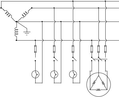
The existence of dual voltage levels in a center-grounded wye system enables the use of loads with di erent voltage ratings. For example, in a 208/120 wye system, a three-phase motor with windings rated for 208 volts would draw power from the three “hot” conductors directly, while light bulbs rated for 120 volts would connect between any “hot” conductor and the neutral:
Wye-connected
power source (208V/120V)
Fuse
Switch 
120 volt 120 volt 120 volt lamp lamp lamp
A
B
N
C
Fuses
 3-pole switch
208 volt motor
A good practice in such systems is to equally spread the 120 volt loads among the three phases, so that (ideally) the phase loading on the source will be nicely balanced when all loads are operating. If the loading is perfectly balanced, in fact, the neutral conductor will carry no current at the point where it connects to the center of the wye.
Note the use of fuses on all the “hot” load conductors, but no fuses on any “neutral” (grounded) conductor. The reason for this is so that in the event of a fuse blowing, only the hot conductor(s) will be disconnected from the load, leaving the neutral conductor connected and thereby maintaining the lowest possible potential at the load relative to earth ground.
456 |
CHAPTER 5. AC ELECTRICITY |
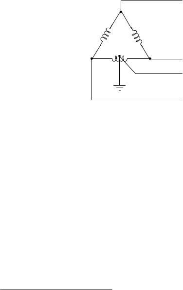
In delta-connected systems, there is no “natural” point to connect to earth ground as there is in wye-connected systems. The most common grounding configuration for a delta-connected source is shown here, sometimes called the “high-leg” connection. Here, one of the source’s phase coils is center-tapped to provide a connection point for earth ground:
Delta-connected power source
A
C
N
B
This configuration yields three di erent voltages available to power loads. If the phase voltage of the delta-connected source is 240 volts, the three available voltages are:
•240 volts (between A-B, B-C, and A-C)
•120 volts (between B-N and C-N)
•208 volts (between A-N)45
A disadvantage of this configuration is that the lower-voltage loads cannot be balanced among all three phase coils of the source as they can in wye-connected systems. Any single-phase loads (those connected between any one “hot” conductor and the neutral conductor) inevitably place more burden on the B-C phase coil than the other two phase coils. However, this imbalance is often negligible in industrial settings where three-phase loads are predominant and single-phase loads are few (and low-wattage).
45A colorful term for this odd voltage is bastard voltage.