

7.5. INSTRUMENT AND PROCESS EQUIPMENT SYMBOLS |
543 |
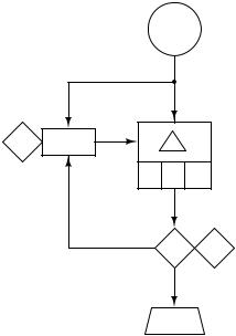
Rectangular blocks such as the Δ, P, I, and D shown in this diagram represent automatic functions. Diamond-shaped blocks such as the A and T blocks are manual functions (i.e. set by a human operator). Showing even more detail, the following functional diagram indicates the presence of setpoint tracking in the controller algorithm, a feature that forces the setpoint value to equal the process variable value any time the controller is in manual mode:
FT Flow transmitter
A T
PID controller
P I D
T A
FCV Flow control valve
Here we see a new type of line: dashed instead of solid. This too has meaning in the world of functional diagrams. Solid lines represent analog (continuously variable) signals such as process variable, setpoint, and manipulated variable. Dashed lines represent discrete (on/o ) signal paths, in this case the auto/manual state of the controller commanding the PID algorithm to get its setpoint either from the operator’s input (A) or from the process variable input (the flow transmitter: FT).
7.5Instrument and process equipment symbols
This section shows some of the many instrument symbols found in di erent types of technical diagrams used to document instrument systems.
544 |
CHAPTER 7. INSTRUMENTATION DOCUMENTS |
7.5.1Line types
|
Instrument supply |
|
|
|
or process connection |
|
|
Process flow line |
(impulse line) |
Waveguide |
Undefined |
Pneumatic signal |
Pneumatic signal |
|
|
|
(continuous) |
(discrete -- on/off) |
Capillary tube |
Hydraulic signal |
|
Electric signal |
Electric signal |
|
|
|
(continuous) |
(discrete -- on/off) |
|
Data link |
|
|
|
Fieldbus network |
(smart instrument) |
|
(or) |
(or) |
|
|
|
Mechanical link |
Data link |
Data link |
Radio link |
|
(common system) |
(independent systems) |
|||
|
|
Sonic or other wave
Note: the single backslash signifying a “discrete” or “binary” signal type has been removed from the ISA standard as of the 2009 ANSI publication. Regular pneumatic and electrical line symbols may represent either continuous or discrete states. The “triple-slash” alternative linetype for electrical symbols is also absent from the 2009 ANSI/ISA standard.
7.5. INSTRUMENT AND PROCESS EQUIPMENT SYMBOLS |
545 |
7.5.2Process/Instrument line connections
Generic |
Threaded |
Socket welded |
|||||||
|
|
|
|
|
|
|
|
|
|
|
|
|
|
|
|
|
|
|
|
|
|
|
|
|
|
|
|
|
|
Flanged |
Heat/cool traced |
(direct) Welded |
||||||||
|
|
|
|
|
|
|
|
|
|
|
|
|
|
|
|
|
|
|
|
|
|
|
|
|
|
|
|
|
|
|
|
|
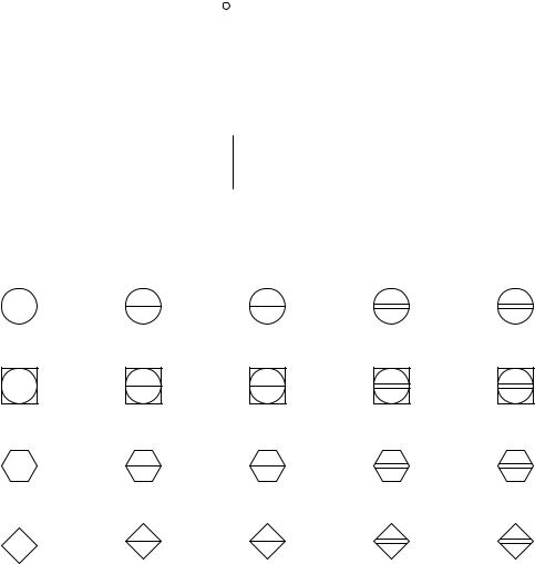
7.5.3Instrument bubbles
|
Main control panel |
Main control panel |
Auxiliary control panel |
Auxiliary control panel |
Field mounted |
front-mounted |
rear-mounted |
front-mounted |
rear-mounted |
Discrete instruments
Shared instruments
Computer
function
Logic
546 |
CHAPTER 7. INSTRUMENTATION DOCUMENTS |
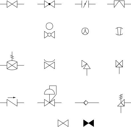
7.5.4Process valve types
Valve |
Globe valve |
Butterfly valve Diaphragm valve |
(generic) |
|
|
|
|
|
|
Ball valve |
|
Characterized |
Plug valve |
|||||||||||
Gate valve |
|
|
ball valve |
|||||||||||||||||
|
|
|
|
|
|
|
|
|
|
|
|
|
|
|
|
|
||||
|
|
|
|
|
|
|
|
|
|
|
|
|
|
|
|
|
|
|
|
|
|
|
|
|
|
|
|
|
|
|
|
|
|
|
|
|
|
|
|
|
|
|
|
|
|
|
|
|
|
|
|
|
|
|
|
|
|
|
|
|
|
|
|
|
|
|
|
|
|
|
|
|
|
|
|
|
|
|
|
|
|
|
|
|
|
|
|
|
|
|
|
|
|
|
|
|
|
|
|
|
|
|
|
|
|
|
|
|
|
|
|
|
|
|
|
|
|
|
|
|
|
|
|
|
|
Pneumatic pinch valve
Saunders valve |
Angle valve |
Three-way valve |
||||||||||
|
|
|
|
|
|
|
|
|
|
|
|
|
|
|
|
|
|
|
|
|
|
|
|
|
|
|
|
|
|
|
|
|
|
|
|
|
|
|
Pressure regulator
Pressure relief Check valve or safety valve
(generic)
Ball check valve
Valve status:
Open Closed
(may pass fluid) |
(blocks fluid flow) |
Valve status may or may not be shown in a process diagram. If you happen to see solid-colored valve symbols anywhere in a diagram, you know that status is being represented. If you see no solid-colored valves anywhere in the diagram, either all valves are shown open or else status is not represented at all.