

520 |
CHAPTER 6. INTRODUCTION TO INDUSTRIAL INSTRUMENTATION |
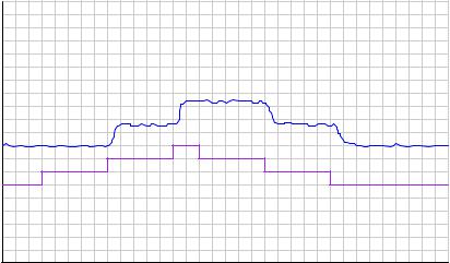
This next example shows another type of problem revealed by a trend recording during manualmode testing:
|
100 |
|
|
95 |
|
|
90 |
|
|
85 |
|
|
80 |
|
|
75 |
|
|
70 |
|
|
65 |
|
|
60 |
|
% |
55 |
PV |
50 |
||
|
45 |
|
|
40 |
|
|
35 |
Output |
|
30 |
|
|
25 |
|
|
20 |
|
|
15 |
|
|
10 |
|
|
5 |
|
|
0 |
|
Time 
Here, we see the process quickly responding to all step-changes in controller output except for those involving a change in direction. This problem is usually caused by mechanical friction in the final control element (e.g. “sticky” valve stem packing in a pneumatically-actuated control valve), and is analogous to “loose” steering in an automobile, where the driver must turn the steering wheel a little bit extra after reversing steering direction. Anyone who has ever driven an old farm tractor knows what this phenomenon is like, and how it detrimentally a ects one’s ability to steer the tractor in a straight line.
Sometimes it becomes useful to temporarily place a recorder into an instrumentation system for diagnostic purposes. On the simplest level, this might consist of a digital multimeter (DMM) connected to measure signal voltage or current, with its “minimum/maximum” capture mode engaged. On a more complex level, this might be a personal computer running data graphing software, connected to the instrumentation circuit through a data acquisition (DAQ) module converting the circuit’s analog voltage or current signals into digital values readable by the computer.
6.4.3Process switches and alarms
Another type of instrument commonly seen in measurement and control systems is the process switch. The purpose of a switch is to turn on and o with varying process conditions. Usually, switches are used to activate alarms to alert human operators to take special action. In other situations, switches are directly used as control devices.
6.4. OTHER TYPES OF INSTRUMENTS |
521 |
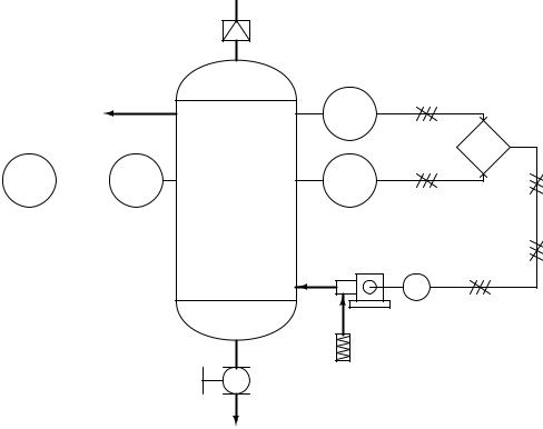
The following P&ID of a compressed air control system shows both uses of process switches:
PAH  PSHH
PSHH
PSH
PSL
Compressor
M 
Filter
Blowdown
The “PSH” (pressure switch, high) activates when the air pressure inside the vessel reaches its high control point. The “PSL” (pressure switch, low ) activates when the air pressure inside the vessel drops down to its low control point. Both switches feed discrete (on/o ) electrical signals to a logic control device (symbolized by the diamond) which then controls the starting and stopping of the electric motor-driven air compressor.
Another switch in this system labeled “PSHH” (pressure switch, high-high) activates only if the air pressure inside the vessel exceeds a level beyond the high shut-o point of the high pressure control switch (PSH). If this switch activates, something has gone wrong with the compressor control system, and the high pressure alarm (PAH, or pressure alarm, high) activates to notify a human operator.
All three switches in this air compressor control system are directly actuated by the air pressure in the vessel: in other words, these are direct process-sensing switches. It is possible, however, to build switch devices that interpret standardized instrumentation signals such as 3 to 15 PSI (pneumatic) or 4 to 20 milliamps (analog electronic), allowing us to build on/o control systems and alarms for any type of process variable measurable with a transmitter.
522 |
CHAPTER 6. INTRODUCTION TO INDUSTRIAL INSTRUMENTATION |
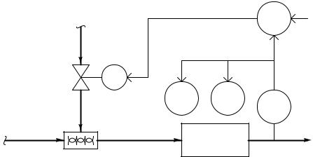
For example, the chlorine wastewater disinfection system shown earlier may be equipped with a couple of electronic alarm switches to alert an operator if the chlorine concentration ever exceeds pre-determined high or low limits:
Chlorine supply |
AIC |
SP |
|
M |
|
|
|
AAL |
AAH |
Cl2 |
|
|
|
AT |
|
Influent |
Contact |
Effluent |
|
chamber |
|||
|
|
||
Mixer |
|
|
The labels “AAL” and “AAH” refer to analytical alarm low and analytical alarm high, respectively. Note how the diagram shows these two alarm units connected to the electronic (4- 20 mA) signal output by the chlorine analyzer (AT). This tells us the AAL and AAH alarm units are really just electronic circuits, alarming if the analytical transmitter’s 4-20 mA analog signal falls below (AAL) or exceeds (AAH) certain pre-set limits. As such, the AAL and AAH alarms do not directly sense the chlorine concentration in the water, but rather indirectly sense it by monitoring the chlorine analyzer’s 4-20 milliamp output signal.
Since both alarms work o the 4 to 20 milliamp electronic signal output by the chlorine analytical transmitter (AT) rather than directly sensing the process, their construction is greatly simplified. If these were process-sensing switches, each one would have to be equipped with the analytical capability of directly sensing chlorine concentration in water. In other words, each switch would have to be its own self-contained chlorine concentration analyzer, with all the attendant complexity.
6.4. OTHER TYPES OF INSTRUMENTS |
523 |
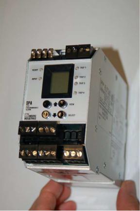
An example of an electronic alarm module (triggered by a 4-20 mA current signal coming from a transmitter) is the Moore Industries model SPA (“Site Programmable Alarm”), shown here:
In addition to providing alarm capability, this SPA module also provides a digital display (a small LCD screen) to show the analog signal value for operational or diagnostic purposes.
Like all current-operated alarm modules, the Moore Industries SPA may be configured to “trip” electrical contacts when the current signal reaches a variety of di erent programmed thresholds. Some of the alarm types provided by this unit include high process, low process, out-of-range, and high rate-of-change.
524 |
CHAPTER 6. INTRODUCTION TO INDUSTRIAL INSTRUMENTATION |
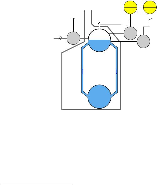
In a similar manner, we may add pressure-actuated process alarm switches to pneumatic (3-15 PSI) signal lines coming from pneumatic transmitters to add alarm capability to a system designed for continuous measurement. For example, if highand low-alarm capability were desired for the steam drum water level process described earlier in this chapter, one could add a pair of pressureactuated switches to the pneumatic level transmitter’s 3-15 PSI output signal line:
LAL |
LAH Alarm lights located |
|
in main control room |
wires wires
Pressure-actuated
alarm switches
Exhaust stack
LSL |
LSH |
A.S. |
|
|
|
||
|
|
tube |
Steam |
tube |
tube |
|
Steam drum |
|
|
LT |
|
tube tube |
tube |
|
|
|
|
water
(to pneumatic |
|
|
control system) |
|
Riser |
|
|
tubes |
Boiler |
|
Downcomer |
|
||
|
tubes |
Mud drum
These two pressure-actuated switches serve as water level alarms, because the air pressure signal actuating them comes from the pneumatic level transmitter, which outputs an air pressure signal in direct proportion to water level in the boiler’s steam drum. Even though the physical stimulus actuating each switch is an air pressure, the switches still serve the purpose of liquid level alarm signaling because that air pressure is an analogue (representation) of water level in the steam drum. In other words, these two alarm switches (LSL and LSH) indirectly sense water level by monitoring the pneumatic signal pressure output by the level transmitter (LT).
6.4. OTHER TYPES OF INSTRUMENTS |
525 |
The alternative to pressure-actuated water level alarm switches would be independent levelsensing switches attached directly to the steam drum, each switch equipped with its own means3 of directly sensing water level:
Alarm lights located in main control room
|
Exhaust stack |
LAH |
LAL |
|
|
|
|
||
|
A.S. |
|
|
|
|
|
Steam |
|
|
|
|
|
|
Level-actuated |
(to pneumatic |
|
Steam drum |
LSH |
alarm switches |
|
|
|||
LT |
|
|
||
control system) |
|
|
LSL |
|
|
water |
|
||
|
|
|
||
|
|
|
|
|
|
|
Riser |
|
|
|
|
tubes |
|
|
|
Boiler |
Downcomer |
|
|
|
tubes |
|
|
|
Mud drum
It should be mentioned that the choice between using process alarm switches directly actuated by the process versus alarm switches actuated by a transmitter’s analog signal is not arbitrary. In the system where the two alarm switches actuate from the transmitter’s 3-15 PSI output signal, the integrity of the water level control and that of the highand low-level alarms all depend on the proper function of one transmitter. If that one transmitter were to fail, all three system functions would be compromised. This elevates the importance of a single instrument, which is generally not desirable from the perspective of reliability and process safety. In the system where each level alarm switch independently senses steam drum water level, one device may fail without compromising either of the other two functions. This independence is desirable because it greatly reduces the probability of “common-cause” failures, where a single fault disables multiple system functions. The final determination should be based on a rigorous analysis of device versus system reliability, which is typically the task of a process engineer.
3These might be float-driven switches, where each switch is mechanically actuated by the buoyancy of a hollow metal float resting on the surface of the water. Another technology uses metal electrodes inserted into the water from above, sensing water level by electrical conductivity: when the water level reaches the probe’s tip, an electrical circuit is closed. For more information on liquid level switches, refer to section 9.6 beginning on page 675.
526 |
CHAPTER 6. INTRODUCTION TO INDUSTRIAL INSTRUMENTATION |
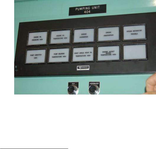
Process alarm switches may be used to trigger a special type of indicator device known as an annunciator. An annunciator is an array of indicator lights and associated circuitry designed to secure a human operator’s attention4 by blinking and sounding an audible buzzer when a process switch actuates into an abnormal state. The alarm state may be then “acknowledged” by an operator pushing a button, causing the alarm light to remain on (solid) rather than blink, and silencing the buzzer. The indicator light does not turn o until the actual alarm condition (the process switch) has returned to its regular state.
This photograph shows an annunciator located on a control panel for a large engine-driven pump. Each white plastic square with writing on it is a translucent pane covering a small light bulb. When an alarm condition occurs, the respective light bulb flashes, causing the translucent white plastic to glow, highlighting to the operator which alarm is active:
Note the two pushbutton switches below labeled “Test” and “Acknowledge.” Pressing the “Acknowledge” button will silence the audible buzzer and also turn any blinking alarm light into a steady (solid) alarm light until the alarm condition clears, at which time the light turns o completely. Pressing the “Test” button turns all alarm lights on, to ensure all light bulbs are still functional.
4D.A. Strobhar, writing in The Instrument Engineers’ Handbook on the subject of alarm management, keenly observes that alarms are the only form of instrument “whose sole purpose is to alter the operator’s behavior.” Other instrument devices work to control the process, but only alarms work to control the human operator.
6.4. OTHER TYPES OF INSTRUMENTS |
527 |
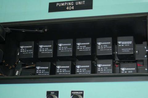
Opening the front panel of this annunciator reveals modular relay units controlling the blinking and acknowledgment latch functions, one for each alarm light:
This modular design allows each alarm channel to be serviced without necessarily interrupting the function of the other channels in the annunciator panel.
528 |
CHAPTER 6. INTRODUCTION TO INDUSTRIAL INSTRUMENTATION |
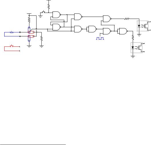
A simple logic gate circuit illustrates the acknowledgment latching feature (here implemented by an S-R latch circuit) common to all process alarm annunciators:
VDD
|
|
|
10 kΩ |
Alarm annunciator circuit |
|
|
Ack |
with "acknowledge" |
|
|
|
|
||
|
|
|
|
|
|
|
VDD |
|
|
|
|
|
|
1 kΩ |
|
10 kΩ |
|
|
|
Process |
|
|
|
Lamp |
(NC) |
|
|
contact |
|
switch |
|
|
|
|
|
|
|
|
P |
Process |
|
10 kΩ |
|
1 kΩ |
(NO) |
|
Pulse from |
||
|
|
|||
switch |
|
|
|
555 timer circuit |
|
|
|
|
Buzzer |
|
|
|
|
contact |
Panel-mounted annunciators are becoming a thing of the past, as computer-based alarm displays replace them with advanced capabilities such as time logging, first-event5 recording, and multiple layers of acknowledgment/access. Time logging is of particular importance in the process industries, as the sequence of events is often extremely important in investigations following an abnormal operating condition. Knowing what happened, and exactly when it happened is much more informative than simply knowing which alarms have tripped.
5When a complex machine or process with many shutdown sensors automatically shuts down, it may be di cult to discern after the fact which shutdown device was responsible. For instance, imagine an engine-powered generator automatically shutting down because one of the generator’s “trip” sensors detected an under-voltage condition. Once the engine shuts down, though, multiple trip sensors will show abnormal conditions simply because the engine is not running anymore. The oil pressure sensor is one example of this: once the engine shuts down, there will no longer be any oil pressure, thus causing that alarm to activate. The under-voltage alarm falls into this category as well: once the engine shuts down, the generator will no longer be turning and therefore its output voltage must be zero. The problem for any human operator encountering the shut-down engine is that he or she cannot tell which of these alarms was the initiating cause of the shutdown versus which of these alarms simply activated after the fact once the engine shut o . An annunciator panel showing both an under-voltage and a low oil pressure light does not tell us which event happened first to shut down the generator. A “first-event” (sometimes called a “first-out”) annunciator, however, shows which trip sensor was the first to activate, thus revealing the initiating cause of the event.