

5.3. SERIES AND PARALLEL CIRCUITS |
361 |
5.3Series and parallel circuits
Impedance in a series circuit is the orthogonal sum of resistance and reactance:
q
Z = R2 + (XL2 − XC2 )
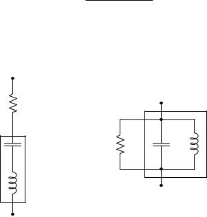
Equivalent series and parallel circuits are circuits that have the exact same total impedance as one another, one with series-connected resistance and reactance, and the other with parallelconnected resistance and reactance. The resistance and reactance values of equivalent series and parallel circuits may be expressed in terms of those circuits’ total impedance:
Rseries
Rparallel |
Xparallel |
Xseries
If the total impedance of one circuit (either series or parallel) is known, the component values of the equivalent circuit may be found by algebraically manipulating these equations and solving for the desired R and X values:
Z2 = RseriesRparallel |
Z2 = XseriesXparallel |
5.4Transformers
The transformer is one of the most important components in all of AC circuitry. Principally used to “step” between di erent values of AC voltage and current in power systems, transformers find uses in many other types of circuits including electronic amplifiers (for impedance matching) and even sensor circuits (sensing physical position).

362 |
CHAPTER 5. AC ELECTRICITY |
5.4.1Basic principles
Before exploring the operation of a transformer, it is useful to review the operation of a simple inductor, which is nothing more than a coil of wire usually wrapped around a ferromagnetic core material:
iron core |
φ |
φ |
I
AC voltage source
I
If we apply an alternating (AC) voltage to this coil, it will generate an alternating magnetic field in the core. Just how much magnetic flux (φ) will develop in the core depends on how much voltage we apply to the coil. The fundamental relationship between voltage and magnetic flux for any conductive coil is given by Faraday’s Law of Electromagnetic Induction3:
V = N dφdt
Where,
V = Voltage applied to the coil or induced by the coil (volts) N = Number of turns of wire
dφdt = Rate of change of magnetic flux (Webers per second)
3At first it may seem strange to apply Faraday’s Law here, because this formula is typically used to describe the amount of voltage produced by a coil of wire exposed to a changing magnetic field, not the amount of magnetic field produced by an applied voltage. However, the two are closely related because the inductor must produce a voltage drop in equilibrium with the applied voltage just like any other component, in accordance with Kirchho ’s Voltage Law. In a simple circuit such as this where the voltage source directly connects to the inductor (barring any resistive losses in the connecting wires), the coil’s induced voltage drop must exactly equal the source’s applied voltage at all points in time, and so Faraday’s Law works just as well to describe the source’s applied voltage as it does to describe the coil’s induced voltage. This is the principle of self-induction.

5.4. TRANSFORMERS |
363 |
If the applied voltage is sinusoidal (i.e. shaped like a sine wave), then the magnetic flux magnitude will trace a cosine wave over time. We may demonstrate this mathematically by substituting sin ωt (the sine of some frequency ω at any particular point in time t) for V in Faraday’s equation and integrating:
|
V = N |
dφ |
|
|
|
|
|
|
dt |
|
|
|
|||
|
|
|
|
|
|||
|
sin ωt = N |
dφ |
|
|
|||
|
dt |
|
|||||
|
|
|
|
||||
|
sin ωt dt = N dφ |
|
|||||
Z |
sin ωt dt = Z |
N dφ |
|||||
Z |
sin ωt dt = N |
Z |
dφ |
||||
1
−ω cos ωt + φ0 = N φ
1
φ = −N ω cos ωt + φ0
Thus, the amount of magnetic flux (φ) in the core at any point in time t is proportional to the cosine of the frequency-time function ωt plus any residual magnetism (φ0) the core happened to start out with before any voltage was applied to the coil.
The amount of current drawn by this inductor depends on the reluctance of the core’s magnetic “circuit” and the number of turns in the coil (N ). The less reluctance o ered by the magnetic path, the less current will be necessary to generate the requisite magnetic field to balance the applied voltage. If we were to take two perfect inductors (i.e. lacking wire resistance) – one with a heavy ferrous core and one with a light ferrous core (or even an air core) – and apply the same AC voltage to them, they would both generate the exact same strength of alternating magnetic field, but the inductor with the lesser core would draw more current from the source in doing so. In other words, the latter inductor would exhibit less reactance (i.e. fewer ohms) to oppose current.
364 |
CHAPTER 5. AC ELECTRICITY |
Things get interesting if we wrap a second coil of wire around the same core as the first. For the sake of analysis we will label voltage polarities at one of the peaks of the AC source:
iron core |
φ |
φ |
I
AC |
I |
I |
|
voltage |
|||
|
R |
||
source |
|
I
At that moment in time when the top terminal of the source is positive and the bottom terminal is negative, we see that the first coil drops the same voltage (due to self-induction), and that the second coil drops the same voltage as well (due to mutual induction). The polarity of both coils’ voltages are identical because they are wrapped in the same direction around the core and they both experience the same magnetic flux (φ). When we examine the directions of current through each coil, however, we see they are opposite one another: the left-hand coil acts as a load (drawing energy from the AC voltage source) while the right-hand coil acts as a source (providing energy to the resistive load).
What we have created here is a true transformer : an electromagnetic component transferring energy from electric form to magnetic form and back again to electric form. The AC voltage source is able to energize the resistive load without direct conductive connection between the two, since the magnetic flux serves as the energy “link” between the two circuits.
Transformers are typically drawn as a set of coils sharing a common core. The coil connected to an electrical source is called the primary, while the coil connected to an electrical load is called the secondary. If the core is ferromagnetic, it is shown as a set of parallel lines between the coils:
A simple transformer circuit
Primary |
Secondary |
5.4. TRANSFORMERS |
365 |
5.4.2Loading e ects
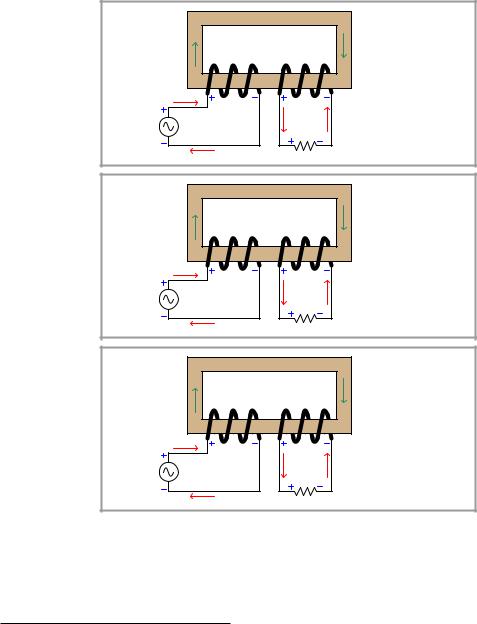
We may explore transformer behavior by observing the e ects of powering one with a constant4- voltage AC source and varying the load resistance:
|
|
φ |
iron core |
|
|
|
Normal load |
|
|
|
|
|
|
R = Normal |
|
|
|
|
|
|
|
|
|
|
|
|
|
|
|
φ |
VS = Normal |
|
|
|
|
|
|
|
|
|
|
|
|
|
|
|
IS = Normal |
AC |
IP |
VP |
|
VS |
|
|
φ = Normal |
|
IS |
IS |
|
|
|||
voltage |
|
|
|
|
VP = Normal |
||
|
|
|
R |
|
|
||
source |
|
|
|
|
|
IP = Normal |
|
|
|
IP |
|
|
|
|
|
|
|
|
|
|
|
|
|
|
|
φ |
iron core |
|
|
|
Light load |
|
|
|
|
|
|
R = Large |
|
|
|
|
|
|
|
|
|
|
|
|
|
|
|
φ |
VS = Normal |
|
|
|
|
|
|
|
|
|
|
|
|
|
|
|
IS = Small |
AC |
IP |
VP |
|
VS |
|
|
φ = Normal |
|
IS |
IS |
|
|
|||
voltage |
|
|
|
|
VP = Normal |
||
|
|
|
R |
|
|
||
source |
|
|
|
|
|
IP = Small |
|
|
|
IP |
|
|
|
|
|
|
|
|
|
|
|
|
|
|
|
φ |
iron core |
|
|
|
Heavy load |
|
|
|
|
|
|
R = Small |
|
|
|
|
|
|
|
|
|
|
|
|
|
|
|
φ |
VS = Normal |
|
|
|
|
|
|
|
|
|
|
|
|
|
|
|
IS = Large |
AC |
IP |
VP |
|
VS |
|
|
φ = Normal |
|
IS |
IS |
|
|
|||
voltage |
|
|
|
|
VP = Normal |
||
|
|
|
R |
|
|
||
source |
|
|
|
|
|
IP = Large |
|
|
|
IP |
|
|
|
|
|
|
|
|
|
|
|
|
Observe how voltage at both coils is una ected by load, and similarly how the magnetic flux remains unchanged under di erent load conditions. The secondary coil acts like a voltage source to the resistive load, reflecting the nature of the primary coil’s source behavior. The magnetic flux amplitude is una ected by secondary loading in order to satisfy Kirchho ’s Voltage Law and Faraday’s Law at the primary coil: the coil’s voltage drop must be equal and opposite to the source’s
4In this context, “constant” means an alternating voltage with a consistent peak value, not “constant” in the sense that a DC source is constant at all points in time.
366 |
CHAPTER 5. AC ELECTRICITY |
applied voltage, and so the magnetic flux must alternate at the same rates and reach the same peaks so long as the primary source voltage does the same.
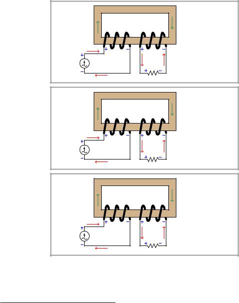
Continuing our exploration of transformer behavior, we will now power one with a constant5- current AC source and vary the load resistance:
|
|
φ |
iron core |
|
|
|
Normal load |
|
|
|
|
|
|
R = Normal |
|
|
|
|
|
|
|
|
|
|
|
|
|
|
|
φ |
VS = Normal |
|
|
|
|
|
|
|
|
|
|
|
|
|
|
|
IS = Normal |
AC |
IP |
VP |
|
VS |
|
|
φ = Normal |
|
IS |
IS |
|
|
|||
current |
|
|
|
|
VP = Normal |
||
|
|
|
R |
|
|
||
source |
|
|
|
|
|
IP = Normal |
|
|
|
IP |
|
|
|
|
|
|
|
|
|
|
|
|
|
|
|
φ |
iron core |
|
|
|
Light load |
|
|
|
|
|
|
R = Small |
|
|
|
|
|
|
|
|
|
|
|
|
|
|
|
φ |
VS = Small |
|
|
|
|
|
|
|
|
|
|
|
|
|
|
|
IS = Normal |
AC |
IP |
VP |
|
VS |
|
|
φ = Small |
|
IS |
IS |
|
|
|||
current |
|
|
|
|
VP = Small |
||
|
|
|
R |
|
|
||
source |
|
|
|
|
|
IP = Normal |
|
|
|
IP |
|
|
|
|
|
|
|
|
|
|
|
|
|
|
|
φ |
iron core |
|
|
|
Heavy load |
|
|
|
|
|
|
R = Large |
|
|
|
|
|
|
|
|
|
|
|
|
|
|
|
φ |
VS = Large |
|
|
|
|
|
|
|
|
|
|
|
|
|
|
|
IS = Normal |
AC |
IP |
VP |
|
VS |
|
|
φ = Large |
|
IS |
IS |
|
|
|||
current |
|
|
|
|
VP = Large |
||
|
|
|
R |
|
|
||
source |
|
|
|
|
|
IP = Normal |
|
|
|
IP |
|
|
|
|
|
|
|
|
|
|
|
|
Observe how current now is the una ected quantity, while voltage and magnetic flux are loaddependent. The secondary coil now acts like a current source to the resistive load, reflecting the nature of the primary coil’s source behavior. As load resistance varies, the secondary coil’s voltage varies proportionately, which in turn demands a commensurate change in magnetic flux.
5In this context, “constant” means an alternating voltage with a consistent peak value, not “constant” in the sense that a DC source is constant at all points in time.