

174 |
CHAPTER 2. PHYSICS |
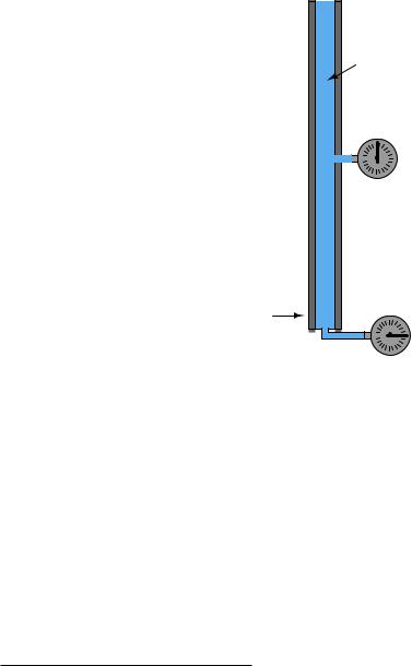
An interesting use of fluid we see in the field of instrumentation is as a signaling medium, to transfer information between places rather than to transfer power between places. This is analogous to using electricity to transmit voice signals in telephone systems, or digital data between computers along copper wire. Here, fluid pressure represents some other quantity, and the principle of force being distributed equally throughout the fluid is exploited to transmit that representation to some distant location, through piping or tubing:
Pressure gauge
Closed bulb filled with fluid
Pipe
This illustration shows a simple temperature-measuring system called a filled bulb, where an enclosed bulb filled with fluid is exposed to a temperature that we wish to measure. A rise in temperature makes the fluid expand and thereby increases pressure sensed at the gauge. The purpose of the fluid here is two-fold: first to sense temperature, and second to relay this temperature measurement a long distance away to the gauge. The principle of even pressure distribution allows the fluid to act as a signal medium to convey the information (bulb temperature) to a distant location.

2.11. FLUID MECHANICS |
175 |
2.11.2Pascal’s Principle and hydrostatic pressure
We learned earlier that fluids tend to evenly distribute any applied force. This fundamental principle is the basis of fluid power and fluid signaling systems, where pressure is assumed to be transferred equally to all points in a confined fluid. In the example of a hydraulic lift given earlier, we assume that the pressure throughout the fluid pathway is equal:
|
|
|
|
|
|
|
|
|
Resulting |
|
|
Applied |
|
|
|
|
force |
|
|
||||
|
|
|
|
(1350 lbs) |
|
|
|||||
|
force |
|
|
|
|
|
|
||||
|
|
|
|
|
|
|
|
||||
(150 lbs) |
Hydraulic lift |
|
|
|
|
|
|||||
|
|
|
|
|
Small |
Large |
|
|
|
|
|
|
|
|
|
|
piston |
piston |
|
|
|
|
|
|
|
|
|
(A = 3 in2) |
|
|
|
|
|||
|
|
|
|
2 |
) |
|
|
|
|
||
Pressure = |
|
|
|
|
|
(A = 27 in |
|
|
|
Pressure = |
|
|
|
|
|
|
|
|
|
Fluid |
|
||
50 PSI |
|
|
|
|
|
|
|
|
|
50 PSI |
|
|
|
|
|
|
|
|
|
|
|
||
|
|
|
|
|
|
|
|
|
|
|
|
|
|
|
|
|
|
|
|
|
|
|
|
|
|
|
|
|
|
||||||
Pressure = |
Pressure = |
|
|
||||||||
|
|
50 PSI |
|
50 PSI |
|
|
|||||
If additional force is applied to the small piston (say, 160 lbs instead of 150 lbs), the fluid pressure throughout the system will increase, not just the fluid pressure in the vicinity of the piston. The e ect of this additional force will be immediately62 “felt” at all points of the system. The phenomenon of pressure changes being evenly distributed throughout an enclosed fluid is called Pascal’s principle.
Pascal’s principle is really nothing more than the direct consequence of fluids’ ability to flow. The only way an additional applied pressure would not be transmitted to all points within a confined fluid volume is if the fluid molecules were somehow not free to move. Since they are mobile, any compression applied to one region of that fluid will propagate to all other regions within that fluid volume. As fluid molecules are subjected to greater pressure, they naturally try to migrate to regions of lower pressure where they “bump up” against other fluid molecules, distributing that increased pressure in doing so.
62There is actually a speed of propagation to this increase in pressure, and it is the speed of sound within that particular fluid. This makes sense, since sound waves are nothing more than rapidly-changing regions of pressure within a material.

176 |
CHAPTER 2. PHYSICS |
Pascal’s principle tells us any change in applied pressure to a confined fluid will be distributed evenly throughout, but it does not say pressure will be the same throughout all points. If forces other than those applied to pistons exert pressure on the fluid, we may indeed experience gradients of pressure throughout a confined fluid volume.
In cases where we are dealing with tall columns of dense fluid, there is another force we must consider: the weight of the fluid itself. Suppose we took a cubic foot of water which weighs approximately 62.4 pounds, and poured it into a very tall vertical tube with a cross-sectional area of 1 square inch:
Water column
 weight = 62.4 lbs
144 ft
(1728 inches)
Cross-sectional
tube area = 1 in2
Pressure gauge
62.4 PSI
Naturally, we would expect the pressure measured at the bottom of this tall tube to be 62.4 pounds per square inch63, since the entire column of water (weighing 62.4 pounds) has its weight supported by one square inch of area.
63Interestingly, the amount of pressure generated by the weight of a fluid depends only on the height of that fluid column, not its cross-sectional area. Suppose we had a column of water the same height (144 feet) but in a tube having an area twice as large: 2 square inches instead of 1 square inch. Twice the area means twice the volume of water held in the tube, and therefore twice the weight (124.8 lbs). However, since this greater weight is distributed over a proportionately greater area at the bottom of the tube, the pressure there remains the same as before: 124.8 pounds ÷ 2 square inches = 62.4 pounds per square inch.
2.11. FLUID MECHANICS |
177 |
If we placed another pressure gauge mid-way up the tube, though, how much pressure would it register? At first you might be inclined to say 62.4 PSI as well, because you learned earlier in this lesson that fluids naturally distribute force throughout their bulk. However, in this case the pressure is not the same mid-way up the column as it is at the bottom:
(Half-way up)
Cross-sectional
tube area = 1 in2
Water column |
weight = 62.4 lbs |
Pressure gauge |
31.2 PSI |
Pressure gauge |
62.4 PSI
The reason for this apparent discrepancy is that the source of pressure in this fluid system comes from the weight of the water column itself. Half-way up the column, the water only experiences half the total weight (31.2 pounds), and so the pressure is half of what it is at the very bottom. We did not consider this e ect before, because we assumed the force exerted by the piston in the hydraulic lift was so large it “swamped” the weight of the fluid itself. Here, with our very tall column of water (144 feet tall!), the e ect of gravity upon the water’s mass is quite substantial. Indeed, without a piston to exert an external force on the water, weight is the only source of force we have to consider when calculating pressure.
This fact does not invalidate Pascal’s principle. Any change in pressure applied to the fluid column will still be distributed equally throughout. For example, if we were to place a piston at the top of this fluid column and apply a force to the fluid, pressure at all points in that fluid column would increase by the same amount64. This is not the same as saying all pressures will be equal throughout the column, however.
64Suppose a 1 square inch piston were set on the top of this tall fluid column, and a downward force of 20 lbs were applied to it. This would apply an additional 20 PSI pressure to the fluid molecules at all points within the column. The pressure at the bottom would be 82.4 PSI, and the pressure at the middle would be 51.2 PSI.
178 |
CHAPTER 2. PHYSICS |
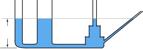
An interesting fact about pressure generated by a column of fluid is that the width or shape of the containing vessel is irrelevant: the height of the fluid column is the only dimension we need to consider. Examine the following tube shapes, all connected at the bottom:
3 feet
Since the force of fluid weight is generated only along the axis of gravitational attraction (straight down), that is the only axis of measurement important in determining “hydrostatic” fluid pressure.
The fixed relationship between the vertical height of a water column and pressure is such that sometimes water column height is used as a unit of measurement for pressure. That is, instead of saying “30 PSI,” we could just as correctly quantify that same pressure as 830.4 inches of water (”W.C. or ”H2O), the conversion factor being approximately 27.68 inches of vertical water column per PSI.
As one might guess, the density of the fluid in a vertical column has a significant impact on the hydrostatic pressure that column generates. A liquid twice as dense as water, for example, will produce twice the pressure for a given column height. For example, a column of this liquid (twice as dense as water) 14 inches high will produce a pressure at the bottom equal to 28 inches of water (28 ”W.C.), or just over 1 PSI. An extreme example is liquid mercury, which is over 13.5 times as dense as water. Due to its exceptional density and ready availability, the height of a mercury column is also used as a standard unit of pressure measurement. For instance, 25 PSI could be expressed as 50.9 inches of mercury (”Hg), the conversion factor being approximately 2.036 inches of vertical mercury column per PSI.
The mathematical relationship between vertical liquid height and hydrostatic pressure is quite simple, and may be expressed by either of the following formulae:
P = ρgh
P = γh
Where,
P = Hydrostatic pressure in units of weight per square area unit: pascals (N/m2) or lb/ft2
ρ = Mass density of liquid in kilograms per cubic meter (metric) or slugs per cubic foot (British) g = Acceleration of gravity (9.81 meters per second squared or 32.2 feet per second squared)
γ = Weight density of liquid in newtons per cubic meter (metric) or pounds per cubic foot (British)
h = Vertical height of liquid column

2.11. FLUID MECHANICS |
179 |
Dimensional analysis – where we account for all units of measurement in a formula – validates the mathematical relationship between pressure, density, and height. Taking the second formula as
an example: |
|
|
|
|
|
ft2 |
P = γh |
1 |
|||
= |
ft3 |
||||
|
lb |
|
|
lb |
ft |
As you can see, the unit of “feet” in the height term cancels out one of the “feet” units in the denominator of the density term, leaving an answer for pressure in units of pounds per square foot. If one wished to set up the problem so the answer presented in a more common pressure unit such as pounds per square inch, both the liquid density and height would have to be expressed in appropriate units (pounds per cubic inch and inches, respectively).
Applying this to a realistic problem, consider the case of a tank filled with 8 feet (vertical) of castor oil, having a weight density of 60.5 pounds per cubic foot:
8 ft |
Castor |
γ = 60.5 lb/ft3 |
oil |
|
|
|
|
|
|
|
P = ??? |
This is how we would set up the formula to calculate for hydrostatic pressure at the bottom of
the tank: |
|
|
|
|
P = γh |
||
P = |
.5 lb |
(8 ft) |
|
60 |
|
||
ft3 |
|||
P = 484 lb ft2
If we wished to convert this result into a more common unit such as PSI (pounds per square inch), we could do so using an appropriate fraction of conversion units:
P = |
ft2 |
|
144 in2 |
|
|
|
|
484 lb |
|
1 ft2 |
|
P = |
3.36 lb |
= 3.36 PSI |
|||
|
|||||
|
|
in2 |
|
|
|

180 |
CHAPTER 2. PHYSICS |
2.11.3Fluid density expressions
The density of any substance is defined as the ratio of its mass or weight to the volume occupied by that mass or weight. Common expressions of density include pounds per cubic foot (British units) and kilograms per cubic meter (metric units). When the substance in question is a liquid, a common form of expression for density is a ratio of the liquid’s density to the density of pure water at standard temperature65. This ratio is known as specific gravity. For example, the specific gravity of glycerin may be determined by dividing the density of glycerin by the density of water:
Specific gravity of any liquid = Dliquid
Dwater
Specific gravity of glycerin = |
Dglycerin |
= |
78.6 lb/ft3 |
= 1.26 |
Dwater |
62.4 lb/ft3 |
The density of gases may also be expressed in ratio form, except the standard of comparison is ambient air instead of water. Chlorine gas, for example, has a specific gravity of 2.47 (each volumetric unit of chlorine having 2.47 times the mass of the same volume of air under identical temperature and pressure conditions). Specific gravity values for gases are sometimes called relative gas densities to avoid confusion with “specific gravity” values for liquids.
As with all ratios, specific gravity is a unitless quantity. In our example with glycerine, we see how the identical units of pounds per cubic foot cancel out of both numerator and denominator, to leave a quotient with no unit at all.
An alternative to expressing fluid density as a ratio of mass (or weight) to volume, or to compare it against the density of a standard fluid such as pure water or air, is to express it as the ratio of volume to mass. This is most commonly applied to vapors such as steam, and it is called specific volume. The relationship between specific volume and density is one of mathematical reciprocation: the reciprocal of density (e.g. pounds per cubic foot) is specific volume (e.g. cubic feet per pound). For example, consulting a table of saturated steam properties, we see that saturated steam at a pressure of 60 PSIA has a specific volume of 7.175 cubic feet per pound. Translating this into units of pounds per cubic feet, we reciprocate the value 7.175 to arrive at 0.1394 pounds per cubic foot.
Industry-specific units of measurement also exist for expressing the relative density of a fluid. These units of measurement all begin with the word “degree” much the same as for units of temperature measurement, for example:
•Degrees API (used in the petroleum industries)
•Degrees Baum´e (used in a variety of industries including paper manufacture and alcohol production)
•Degrees Twaddell (used in the textile industry for tanning solutions and the like)
65Usually, this standard temperature is 4 degrees Celsius, the point of maximum density for water. However, sometimes the specific gravity of a liquid will be expressed in relation to the density of water at some other temperature. In some cases specific gravity is expressed for a liquid at one temperature compared to water at another temperature, usually in the form of a superscript such as 20/4 (liquid at 20 degrees Celsius compared to water at 4 degrees Celsius).

2.11. FLUID MECHANICS |
181 |
The mathematical relationships between each of these “degree” units of density versus specific gravity66 is as follows:
141.5
Degrees API = Specific gravity − 131.5
Degrees Twaddell = 200 × (Specific gravity − 1)
Two di erent formulae exist for the calculation of degrees Baum´e, depending on whether the liquid in question is heavier or lighter than water. For lighter-than-water liquids:
140
Degrees Baum´e (light) = Specific gravity − 130
Note that pure water would measure 10o Baum´e on the light scale. As liquid density decreases, the light Baum´e value increases. For heavier-than-water liquids:
145 Degrees Baum´e (heavy) = 145 − Specific gravity
Note that pure water would measure 0o Baum´e on the heavy scale. As liquid density increases, the heavy Baum´e value increases.
Just to make things confusing, there are di erent standards for the heavy Baum´e scale. Instead of the constant value 145 shown in the above equation (used throughout the United States of America), an older Dutch standard used the same formula with a constant value of 144. The Gerlach heavy Baum´e scale uses a constant value of 146.78:
144 Degrees Baum´e (heavy, old Dutch) = 144 − Specific gravity
146.78 Degrees Baum´e (heavy, Gerlach scale) = 146.78 − Specific gravity
There exists a seemingly endless array of “degree” scales used to express liquid density, scattered throughout the pages of history. For the measurement of sugar concentrations in the food industries, the unit of degrees Balling was invented. This scale was later revised to become the unit of degrees Brix, which is directly proportional to the percent concentration of sugar in the liquid. Another density scale used for expressing sugar concentration is degrees Plato. The density of tanning liquor may be measured in degrees Bark. Milk density may be measured in degrees Soxhlet. Vegetable oil density (and in older times, the density of oil extracted from sperm whales) may be measured in degrees Oleo.
66For each of these calculations, specific gravity is defined as the ratio of the liquid’s density at 60 degrees Fahrenheit to the density of pure water, also at 60 degrees Fahrenheit.
182 |
CHAPTER 2. PHYSICS |
2.11.4Manometers
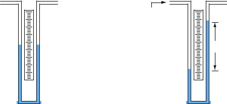
Expressing fluid pressure in terms of a vertical liquid column makes perfect sense when we use a very simple kind of motion-balance pressure instrument called a manometer. A manometer is nothing more than a piece of clear (glass or plastic) tubing filled with a liquid of known density, situated next to a scale for measuring distance. The most basic form of manometer is the U-tube manometer, shown here:
|
U-tube manometer |
|
(vented) |
(vented) |
(vented) |
|
Applied |
|
|
pressure |
|
|
h |
Height |
|
difference |
The basis for all manometers is the mathematical relationship between a liquid’s density (ρ in mass units or γ in weight units) and vertical height. The diameter of the manometer tubes is irrelevant:
P = ρgh
P = γh
Pressure is read on the scale as the di erence in height (h) between the two liquid columns. One nice feature of a manometer is it really cannot become “uncalibrated” so long as the fluid is pure and the assembly is maintained in an upright position. If the fluid used is water, the manometer may be filled and emptied at will, and even rolled up for storage if the tubes are made of flexible plastic.
2.11. FLUID MECHANICS |
183 |
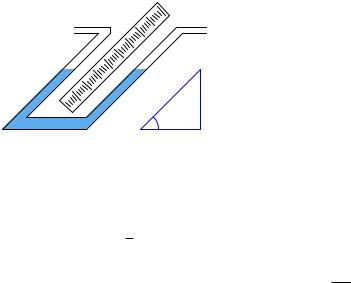
We may create even more sensitive manometers by purposely inclining one or more of the tubes, so that the liquid must travel a farther distance along the tube length to achieve the same vertical shift in height. This has the e ect of “amplifying” the liquid’s motion to make it easier to resolve small pressures:
Inclined manometer
x h
θ
This way, a greater motion of liquid (x) is required to generate the same hydrostatic pressure (vertical liquid displacement, h) than in an upright manometer, making the inclined manometer more sensitive. As the similar triangle in the illustration shows, x and h are related trigonometrically by the sine function:
sin θ = hx
The di erence in fluid column positions measured diagonally along the scale (x) must always be greater than the vertical height di erence between the two columns (h) by a factor of sin1 θ , which will always be greater than one for angles less than 90o. The smaller the angle θ, the greater the ratio between x and h, leading to more sensitivity.
184 |
CHAPTER 2. PHYSICS |
If even more sensitivity is desired, we may construct something called a micromanometer, consisting of a gas bubble trapped in a clear horizontal tube between two large vertical manometer chambers:
A simple micromanometer
Gas |
bubble |
Scale |
Pressure applied to the top of either vertical chamber will cause the vertical liquid columns to shift just the same as any U-tube manometer. However, the bubble trapped in the clear horizontal tube will move much farther than the vertical displacement of either liquid column, owing to the huge di erence in cross-sectional area between the vertical chambers and the horizontal tube. This amplification of motion is analogous to the amplification of motion in a hydraulic piston system (where the smaller piston moves farther than the larger piston), and makes the micromanometer exceptionally sensitive to small pressures.
The movement of the gas bubble within the clear horizontal viewing tube (x) relates to applied pressure by the following formula:
x = γhAlarge
2Asmall
Using water as the working liquid in a standard U-tube manometer, 1 PSI of applied gas pressure results in approximately 27.7 inches of vertical liquid column displacement (i.e. 27.7 inches of height di erence between the two water columns). This relatively large range of motion limits the usefulness of water manometers to modest pressures only. If we wished to use a water manometer to measure the pressure of compressed air in an industrial pneumatic supply system at approximately 100 PSI, the manometer would have to be in excess of 230 feet tall! Clearly, a water manometer would not be the proper instrument to use for such an application.
However, water is not the only viable liquid for use in manometers. We could take the exact same clear U-tube and fill it partially full of liquid mercury instead, which is substantially denser than water. In a mercury manometer, 1 PSI of applied gas pressure results in very slightly more than 2 inches of liquid column displacement. A mercury manometer applied to the task of measuring air pressure in an industrial pneumatic system would only have to be 17 feet tall – still quite large and cumbersome67 for a measuring instrument, but not impossible to construct or to use.
67A colleague of mine told me once of working in an industrial facility with a very old steam boiler, where boiler
2.11. FLUID MECHANICS |
185 |
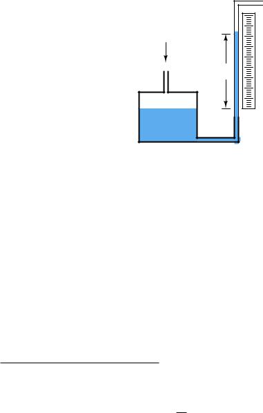
A common form of manometer seen in industrial instrument calibration shops is the well type, consisting of a single vertical tube and a relatively large reservoir (called the “well”) acting as the second column:
"Well" manometer |
|
Applied |
|
pressure |
|
Height |
Scale |
h |
|
Well |
|
Due to the well’s much larger cross-sectional area, liquid motion inside of it is negligible compared to the motion of liquid inside the clear viewing tube. For all practical purposes68, the liquid level inside the “well” is constant, and so the liquid inside the tube moves the full distance equivalent to the applied pressure. Thus, the well manometer provides an easier means of reading pressure: no longer does one have to measure the di erence of height between two liquid columns, only the height of a single column.
steam pressure was actually indicated by tall mercury manometers reaching from floor to ceiling. Operations personnel had to climb a ladder to accurately read pressure indicated by these manometers!
68To give some perspective on just how little the liquid level changes in the well, consider a well-type manometer with a 1/4 inch (inside) diameter viewing tube and a 4-inch diameter circular well. The ratio of diameters for these two liquid columns is 16:1, which means their ratio of areas is 256:1. Thus, for every inch of liquid motion in the
viewing tube, the liquid inside the well moves only 1 of an inch. Unless the viewing tube is quite tall, the amount
256
of error incurred by interpreting the tube’s liquid height directly as pressure will be minimal – quite likely less than what the human eye is able to discern on a ruler scale anyway. If the utmost accuracy is desired in a well manometer, however, we may compensate for the trifling motion of liquid in the well by building a custom ruler for the vertical
tube – one with a 255256 reduced scale (so that 255256 of an inch of liquid motion in the tube reads as exactly 1 inch of liquid column) in the case of the 1/4 inch tube and 4 inch well dimensions.