


314 Spatial Sound
8.1.2 Dolby Surround system
Dolby Surround originated from a type of matrix surround sound technique for film sound reproduction in cinemas by Dolby Laboratories. Drawn a lesson from the 4-2-4 matrix quadraphone, this type of technique was designed on the basis of new consideration; that is, under the condition of the limited capacity of transmission or storage media, a front-biased reproduction of the spatial information of sound is adopted to ensure that localization effects match with the picture. The surround channel is mainly intended for ambient sound and some special effects. In the mid-1970s, Dolby Labs introduced the Dolby Stereo, a four-channel matrix surround sound technique for cinemas. Dolby Stereo involves three original front channels and a surround channel. Dolby Stereo converts the four original signals into two independent signals by matrix encoding to store signals in optical soundtracks in a 35 mm film on the basis of previous 4-2-4 matrix quadraphones. Since the end of the 1970s, Dolby Stereo has been widely used for film sound reproduction in cinema. Dolby Surround technique, a consumer version of Dolby Stereo, was subsequently used for domestic reproduction by using a stereophonic videotype recorder and a laser disk (LD) as signal storage media (Dolby Laboratories, 1998; Julstrom, 1987).
The principles of matrix encoding in Dolby Surround and Dolby Stereo are basically identical. The four original signals, including left, center, and right channel signals in the front and a surround channel signal, are denoted by EL, ER, EC, and ES. They may be correlated or uncorrelated. The encoding equation is given as
ELT EL 0.71EC 0.71jES ERT ER 0.71EC 0.71jES |
(8.1.8) |
They may also be written in a matrix form:
|
|
|
|
|
|
|
|
EL |
|
|
ELT |
|
1 |
0.71 |
0 |
0.71j |
EC |
|
(8.1.9) |
||
|
ERT |
|
|
0.71 |
1 |
0.71j |
|
|
. |
|
|
|
0 |
|
ER |
|
|||||
|
|
|
|
|
|
|
|
|||
|
|
|
|
|
|
|
|
ES |
|
|
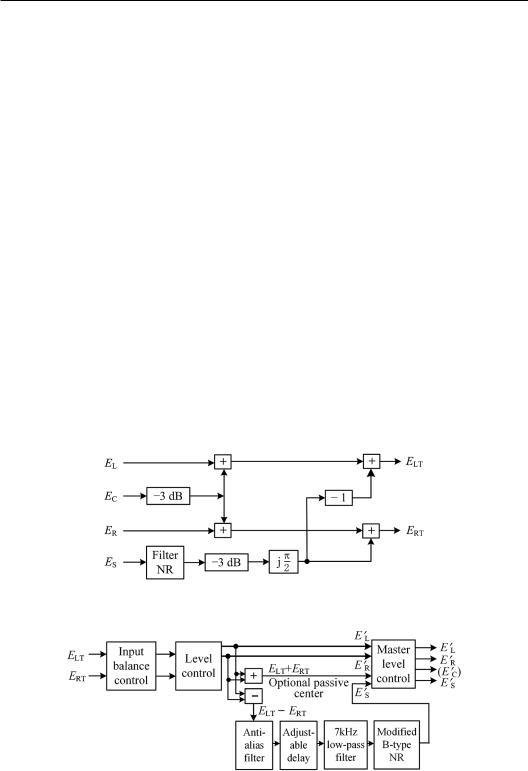
The original left channel signal EL is directly mixed to the ELT channel; the original right channel signal ER is directly mixed to the ERT channel; the center channel signal EC is mixed to ELT andERT channels after a −3 dB attenuation; and the surround channel signal ES is mixed to ELT and ERT channels after ±90° phase shift and a −3 dB attenuation. The subscript LT and RT denote the left total and right total signals, respectively.
Linear (matrix) decoding was used in early Dolby Surround, resulting in four-channel- reproduced signals E′L, E′C, E′R, and E′S. The decoding equation is given as
|
|
|
|
1 |
|
EL |
|
||||
|
|
|
|
|
|
EC |
|
|
0.71 |
||
|
|
|
0 |
||
|
ER |
|
|
|
|
|
|
|
|||
ES |
|
|
0.71 |
||
0 |
|
|
|
|
0.71 |
|
ELT |
(8.1.10) |
|
1 |
|
|
. |
|
|
ERT |
|
||
|
|
|
|
|
0.71 |
|
|
|
|
Substituting Equation (8.1.9) into Equation (8.1.10) leads to
Matrix surround sound 315
|
|
|
|
EL EL 0.71EC 0.71jES |
EC 0.71EL EC 0.71ER |
. |
(8.1.11) |
|
|
||
ER ER 0.71EC 0.71jES |
ES 0.71EL 0.71ER jES |
|
|
After decoding is completed, the crosstalk between opposite channels vanishes, i.e., the separation between opposite channels is infinite. In particular, the original center channel signal does not appear in the surround channel after decoding and vice versa, which is an advantage of Dolby Surround encoding/decoding. However, the magnitude ratio between the crosstalk of an adjacent channel and the desired signal is 0.71/1 = 0.71 (−3 dB), and the separation between adjacent channels is only 3 dB. In fact, crosstalk in traditional 4-2-4 matrix systems is inevitable.
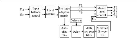
Figure 8.2 shows the block diagram of the Dolby Surround encoder. A band-pass filter within 100 Hz–7 kHz and noise reduction processing are added to the surround channel. Figure 8.3 illustrates the block diagram of the basic Dolby Surround decoder used in early times. The surround channel signal is subjected to an anti-aliasing filter, a low-pass (more strictly a band-pass filter within 100 Hz–7 kHz), and modified Dolby B noise reduction. A low-pass filter is used to reduce the side effects of matrix encoding/decoding. Moreover, an adjustable delay of the order of 20–30 ms is added to the surround channel. This delay aims to take advantage of the precedence effect (Section 1.7.2) to reduce the influence of surround channel signals on front localization.
In domestic use, the loudspeaker configuration for Dolby Surround is similar to that of the 5.1 channel surround sound. It involves the left, center, and right loudspeakers in the front and a pair of surround loudspeakers in the sides and slightly back or slightly above the horizontal plane. The simplest method is to feed the same surround signal to two surround loudspeakers because only a single surround signal is derived after decoding. Some postprocessing techniques, such as signal decorrelation, are also applied to derive two surround
Figure 8.2 Block diagram of a Dolby Surround encoder.
Figure 8.3 Block diagram of a basic Dolby Surround decoder.

316 Spatial Sound
channel signals and improve the perceived effect of ambient sound in reproduction. A threeloudspeaker configuration is also used in the early Dolby Surround reproduction. The left and right channel signals are reproduced by a pair of left and right loudspeakers in the front; the center channel signal is simultaneously reproduced by the left and right loudspeakers with −3 dB attenuation (phantom center); and the surround channel signal is reproduced by a back loudspeaker.
8.1.3 Dolby Pro-Logic decoding technique
Passive decoding is used in early Dolby Surround. In this technique, the coefficients in a decoding matrix are constants. A major problem of passive decoding in Dolby Surround is the crosstalk between adjacent channels that spoil virtual source localization in reproduction. In 1987, logic decoding was used in Dolby Pro-Logic, which was also modified from film sound for domestic or consumer reproduction (Dolby Laboratories, 1998; Hull, 1999), to enhance the separation between channels. Logic decoding is a time-variant and adaptive or active decoding technique through which decoding coefficients vary with instantaneous characteristics or relationship among the encoded signals. The relative magnitude and phase between two encoded signals, namely, ELT and ERT, are detected to evaluate the dominant component of four original signals at each instant. The obtained information enables the adaptive decoder to steer the signals to appropriate channels with a smooth control of gain so that the gains of output channels with dominant component are enhanced, and the gains of other output channels are attenuated. The adaptive decoder enhances the separation between channels up to an order of 30 dB.
To illustrate the principle of Dolby Pro-Logic decoder, a case is considered in which three original front-channel signals are created via pair-wise amplitude panning and the original surround channel signal is an ambient signal. Starting from the direction of the right channel to the direction of the left channel anticlockwise, the original signals of three front channels are created. The second column in Table 8.2 illustrates the variation in the three original front-channel signals and the case of surround channel signal only. The notation “↑”in the table denotes the signal magnitude increases smoothly, and the notation “↓” corresponds to the signal magnitude reduces smoothly. Ideally, the allocation of four-channel signals after adaptive decoding should be identical to that of the original signals.
Table 8.2 Basic information of the adaptive decoding provided by the encoding signals ELT and ERT
|
|
|
Relationship between |
Relationship between |
Target direction |
Original signal |
Encoding signals |
ELT and ERT |
(ELT + ERT) and (ELT − ERT) |
Right |
ER =1, |
ELT = 0 |
ELT = 0 |
Out of phase, |
|
Other = 0 |
ERT = 1 |
|
|ELT +ERT| = |ELT − ERT| |
Right→ Center |
|ER |↓, |EC |↑, |
ELT = 0.71EC |
In phase |
Out of phase, |
|
Other = 0 |
ERT = ER + 0.71EC |
|
|ELT +ERT| > |ELT− ERT| |
Center |
EC = 1, |
ELT = 0.71EC |
In phase, |
| ELT −ERT | = 0 |
|
Other = 0 |
ERT = 0.71EC |
ELT = ERT |
|
Center→Left |
|EC|↓, |EL |↑, |
ELT = EL + 0.71EC |
In phase |
In phase, |
|
Other = 0 |
ERT = 0.71EC |
|
|ELT +ERT| > |ELT − ERT| |
Left |
EL = 1, |
ELT = 1 |
ERT = 0 |
In phase, |
|
Other = 0 |
ERT = 0 |
|
|ELT +ERT| = |ELT − ERT| |
Surround(back) |
ES = 1 |
ELT = −0.71jES |
Out of phase |
|ELT+ERT | = 0 |
|
Other = 0 |
ERT = 0.71jES |
|
|
|
|
|
|
|

Matrix surround sound 317
The third column in Table 8.2 illustrates the two encoded signals ELT and ERT given as Equation (8.1.8). The fourth column in Table 8.1 shows the relative magnitudes and phases between two encoded signals. The relative magnitude and phase change with the variation in the panning of original signals, which provide information on the separation of the front and back dominant components. Thus, the crosstalk between the center and surround channels decreases. When the original signals are panned from the right channel through the center channel to the left channel, ELT and ERT signals are in phase. When the original signal is panned to the full right or full left, either ELT or ERT vanishes. When the original signal is fed to the surround channel only, ELT and ERT are out of phase. Therefore, signal steering in adaptive decoding can be controlled by the detected information from ELT and ERT. When ELT and ERT are in phase, the gain of the surround channel in the decoding outputs is restrained. When either of ELT or ERT vanishes, the gains of surround and center channels in the decoding outputs are restrained. When ELT and ERT are out of phase, the gains of the three frontal channels in the decoding outputs are restrained.
Similarly, the relative magnitude and phase between the sum (ELT + ERT) and difference (ELT − ERT) of the encoded signals in the fifth column of Table 8.2 provide the left–right information of the dominant component. This information is applied to control the signal steering and smooth transition of the gain of the left and right channel signals in the decoding outputs. When the original signal is panned to center or surround channel only, either |ELT − ERT | or |ELT + ERT| vanishes, the gains of the left and right channels in the adaptive decoding outputs are restrained. When the original signal is panned between the right and center channels, signals (ELT + ERT) and (ELT − ERT) are out of phase, the gains of the left and surround channels in the adaptive decoding outputs are restrained, and the gains of the right and center channels in the adaptive decoding outputs are controlled on the basis of the relative magnitude between |ELT + ERT | and |ELT − ERT |. When the original signal is panned between the left and center channels, the signals (ELT + ERT) and (ELT − ERT) are in phase, and the gains of the left and center channels are controlled on the basis of the relative magnitude
between | ELT + ERT | and | ELT − ERT |.
The overall power of all channels outputs in a decoder should be a constant when the coefficients of decoding change adaptively. Therefore, the gain of a channel in the decoding output should be increased smoothly when the gain of an adjacent channel output is reduced smoothly. Moreover, the response time of an adaptive decoder should be chosen carefully. A short response time is beneficial to recreating the virtual source with a rapid change in the direction but is inclined to creating an audible discontinuous artifact.
According to the aforementioned principle, adaptive decoders can be implemented with various methods (Gundry, 2001). The early Dolby Pro-Logic decoder is implemented with an analog circuit. Controlling signals are derived from the relative magnitude and phase between signals ELT and ERT and between (ELT + ERT) and (ELT − ERT). The gain of each channel in the decoding outputs is controlled by voltage-controlled amplifiers. Dolby Pro-Logic decoding can also be implemented via digital signal processing. This function is found in some products of Dolby digital surround sound processor. Figure 8.4 shows the block diagram of a Dolby Pro-Logic decoder.
8.1.4 Some developments on matrix surround sound and logic decoding techniques
Since the end of the 1980s, the development of digital techniques has solved the problems of the transmission and storage of multichannel signals. However, matrix surround sound techniques are still developed because two-channel transmission and storage media still occupy a large proportion in practice even in the age of digital techniques. The transmission and
318 Spatial Sound
Figure 8.4 Block diagram of Dolby Pro-Logic.
storage of two-channel signals reduce the bit rate of data and thus compress the data of multichannel sound.
After the development of Dolby Pro-Logic, various encoding and adaptive decoding techniques for matrix surround sound have also been established. One feature of these new matrix surround sound techniques is that they can manipulate more than four-channel spatial information. For example, in the encoding of five-channel sound signals into two-channel independent signals, the general equation is given as
|
ELT LEL CEC LSELS |
RSERS |
|
(8.1.12) |
|||
|
ERT RER CEC LSELS RSERS. |
||||||
|
|
||||||
Equation (8.1.12) can be written as a matrix form |
|
|
|
||||
|
|
|
|
|
EL |
|
|
ELT |
L |
C |
0 LS |
RS EC |
(8.1.13) |
||
|
|
|
C |
R LS |
|
ER |
|
ERT |
0 |
RS |
|
|
|||
|
|
|
|
|
ELS |
|
|
|
|
|
|
|
|
|
|
|
|
|
|
|
ERS |
|
|
Generally, the encoding coefficients κL, χR, κC, and χC are real values, and κLS, κRS, χLS, and χRS are real or complex values. The coefficients should satisfy |κLS|2 + |χLS |2 =1 and |κRS|2 + |χRS|2 = 1 to maintain the constant overall power of signals after encoding. If κL = χR = 1 and κC = χC = 0.71 are chosen, the original left, center, and right channel signals are encoded identical to those in Dolby Stereo or Dolby Surround. The original leftand right-surround signals are encoded into the independent signals ELT and ERT with appropriate gains and phase shifts.
Different encoding coefficients are used in various five-channel matrix surround sound techniques and systems. Constant coefficients are used in passive encoding. For more sophisticated active or adaptive encoding, encoding coefficients are changed adaptively according to the instantaneous characteristics of input signals to optimize the encoding performance of different signals. The two-channel encoded signals are converted back into five or more channels reproduced signals. Various decoding matrices and methods are used in different matrix surround sound techniques. In addition to decoding the two-channel signals encoded from original five-channel signals, some newly developed decoding methods can decode the encoded signals from Dolby Stereo or Dolby Surround and manipulate the usual two-chan- nel stereophonic signals to obtain five or more channel reproduced signals.

Matrix surround sound 319
A simple choice of encoding coefficients is described as follows (Faller and Schillebeeckx, 2011):
L R 1 C C |
2 |
|
|
|
|
|
|||||
2 |
|
|
|
(8.1.14) |
|||||||
|
|
|
|
|
|
|
|
||||
|
3 |
|
|
|
|
|
|
|
|||
LS |
j |
RS |
1 j LS |
1 j |
RS |
3 |
j. |
||||
2 |
2 |
||||||||||
|
|
|
2 |
|
|
2 |
|
|
|||
Lexicon Logic 7 is another matrix surround sound technique with adaptive decoding developed in the mid of 1990 (Griesinger, 1996, 1997a). It preserves the left–right and front– back separation of the reproduced signals and enhances the front–back balance for different types of program materials. Lexicon Logic 7 is intended for high-quality domestic or consumer reproduction. In addition to be used for reproduction with an accompanying picture, it improves performance for music reproduction. Lexicon Logic 7 encodes the original 5.1-channel signals into two-channel signals and then decodes into fiveor seven-channel signals. The loudspeaker configuration for seven-channel reproduction is similar to that of the discrete 7.1 channel system in Figure 5.10. A pair of side surround loudspeakers improves the lateral localization in reproduction with an accompanying picture and auditory spatial impression in music reproduction.
Two major considerations of Lexicon Logic 7 encoding are as follows:
1. It can effectively encode the original 5.1-channel signals so that the encoded signals can be decoded with minimal loss.
2. The encoded signals should be stereophonically compatible.
An adaptive encoding algorithm is used on the basis of this consideration in Lexicon Logic 7. According to the information detected from the relative magnitudes and phases between the original five-channel inputs, encoding coefficients are changed adaptively. The encoding of the original left, center, and right channel signals is similar to that of Dolby Stereo or Dolby Surround, e.g., taking κL = χR = 1, κC = χC = 0.71 in Equation (8.1.12).
The encoding of original surround channel signals is complicated. In the adaptive encoding algorithm, the encoding coefficients for surround signals in Equation (8.1.12) are written as follows:
LS
LS
0.91
0.38
w E , E |
w |
2 |
E , E |
j |
|
RS |
0.38 |
w |
|
|
E , E |
|
w |
2 |
|
E , E |
|
j |
|
|||||||||||||
|
1 L |
LS |
|
|
|
L |
LS |
|
|
|
|
|
1 |
R |
RS |
|
|
R |
RS |
|
(8.1.15) |
|||||||||||
w E |
, E |
|
w |
2 |
E |
, E |
|
j |
|
|
0.91 w |
|
E , E |
w |
|
|
|
E , E |
j . |
|||||||||||||
|
|
RS |
2 |
|
||||||||||||||||||||||||||||
|
1 L |
LS |
|
|
L |
LS |
|
|
|
|
|
1 |
|
R |
RS |
|
|
|
R |
RS |
|
|
|
|||||||||
Where two functions w1 and w2 vary with the relative magnitude and phase of the original input signals. In the basic operation of the encoder, two functions become w1 = 0, w2 = 1, then κLS = −0.91j, χRS = 0.91j, κRS = −0.38j, χLS = 0.38j. The original surround signals are mixed to the encoded signals with a ±90° phase shift because all the encoding coefficients are imaginary values. For a single original surround signal only (e.g., ELS) or two decorrelated surround signals, the overall power of two encoded signals is identical to that of original signals. In this case, the basic operation of the encoder is appropriate. For two identical original surround signals, the basic operation of the encoder leads to an undesired boost of 1.29 times (2.2 dB) in each encoded output signal. In this case, adaptive encoding algorithm should reduce w2 by a factor up to 1/1.29 or −2.2 dB. Moreover, when the original leftand
320 Spatial Sound
right-surround signals are similar in terms of magnitude but are out of phase, the basic operation of the encoder generates two almost identical encoded signals ELT ≈ ERT. These encoded signals are mistakenly decoded as a center channel signal in reproduction. Through adaptive encoding, w1 increases to create a 90° phase difference between the encoded signals ELT and ERT and thus avoid this error.
For classical music recording, surround channels often record reverberation. To be compatible with stereophonic reproduction, original surround signals are mixed to the two encoded signals with a −3 dB attenuation in accordance with the standard in Europe. In the adaptive encoding in Lexicon Logic 7, the relative signal levels of three original front-channel signals are compared with two original surround channel signals. If the maximum of two surround channel levels is lower than the maximum of the three front-channel levels with −3 dB, the surround channel signals are processed as reverberation and attenuated by changing w2 in Equation (8.1.15). A maximal attenuation of −3 dB is reached when the surround channel level is lower than that of the front-channel level by at least −8 dB.
Lexicon Logic 7 can decode the two encoded signals ELT and ERT into fiveor sevenchannel outputs. The principle of adaptive decoding in Lexicon Logic 7 is similar to that of Dolby Pro-Logic. Different decoding modes are used for music and programs with an accompanying picture. The practical decoder of Lexicon Logic 7 is complicated and described in Griesinger’s studies.
Dolby Labs developed new generations of matrix surround sound and adaptive encoding/ decoding technique. Dolby Pro-Logic II encodes the original 5.1 channel signals into two independent signals by using a matrix method (Dressler, 2000). Encoding is also expressed in Equation (8.1.12), and the encoding coefficients are
L R 1 C C 0.71
LS |
19 j RS |
6 |
j LS |
19 j RS |
6 |
(8.1.16) |
|
j. |
|||||||
25 |
25 |
||||||
|
25 |
|
25 |
|
The 5.1-channel reproduced signals are derived from the two encoded signals via adaptive decoding (Gundry, 2001). In comparison with traditional Dolby Surround and Dolby ProLogic, Dolby Pro-Logic II has two surround channels. All five main channels are full audible bandwidths. Pro-Logic II also enables bass management. In accordance with different modes (such as movie, Pro-Logic, and music modes), Pro-Logic II can decode two-channel encoded signals or upmix stereophonic signals into 5.1-channel outputs. The music mode is mainly for upmixing the two-channel stereophonic inputs into 5.1-channel outputs. A Dolby ProLogic II decoder provides some user-adjustable parameters for optional controls, including dimension (front and back sound field) control and center width control, because universal or optimal methods for upmixing have yet to be developed. A high-frequency shelf filter is also provided in the surround channel to model the high-frequency roll-off of ambience caused by room reflection and absorption. In addition, Dolby Pro-Logic II utilizes feedback control to improve the dynamic characteristic in adaptive decoding.
The Dolby Pro-Logic IIx introduced in 2002 can further decode or upmix the two-channel encoded signals, two-channel stereophonic signals, and 5.1-channel signals into horizontal 6.1- and 7.1-channel signals.
Introduced in 2009, Dolby Pro-Logic IIz embeds two front-height channels into 5.1- or 7.1-channel horizontal surround sound to improve the reproduction of vertical information in the front, leading to 5.1+2 or 7.1+2 channel reproduction (Tsingos et al., 2010). The signals of two front-height channels are mixed with original 5.1- or 7.1-channel signals by matrix encoding and delivered with 5.1- or 7.1-channel media. For example, in 7.1+2
Matrix surround sound 321
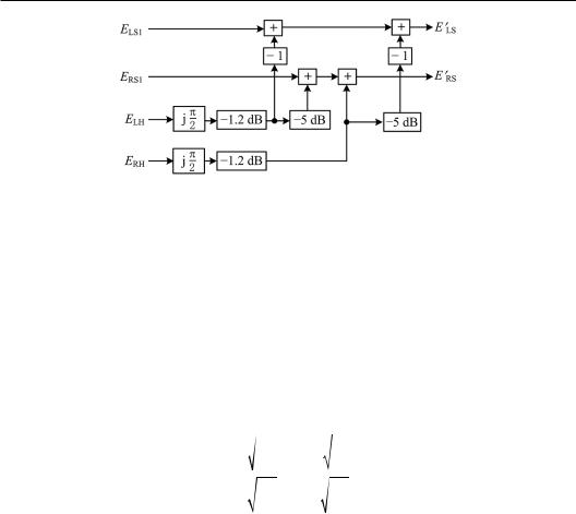
Figure 8.5 Block diagram of a Dolby Pro-Logic IIz encoder.
channel reproduction, original signals involve seven horizontal channel signals, e.g., leftfront EL, center EC, right-front ER, left-side surround ELS1, right-side surround ERS1, left-back surround ELS2, right-back surround ERS2, and two height signals, e.g., the left-front height ELH and right-front height ERH. It also involves a signal ELFE of a low-frequency effect channel.
The signals EL, EC, ER, ELS2, ERS2, and ELFE are delivered separately; the signals ELS1, ERS1, ELH, and ERH are mixed into two signals E′LS and E′RS by encoding matrix and then deliv-
ered. Therefore, all the signals are delivered via 7.1-channel media. Prior to be encoded, the signals ELS1 and ERS1 may be delayed appropriately to reduce their influence on localization. Figure 8.5 illustrates the block diagram of the Dolby Pro-Logic Iizencoder. The encoding equation is given as
|
|
19 |
|
|
6 |
|
||
ELS ELS1 |
|
|
25 jELH |
|
|
|
jERH |
|
|
25 |
|||||||
|
|
|
|
|
|
(8.1.17) |
||
|
|
6 |
|
|
19 |
|
||
ERS ERS1 |
|
|
|
jELH |
25 jERH . |
|||
|
25 |
|||||||
The adaptive decoding outputs of Pro-Logic Iiz are reproduced by 5.1+2 or 7.1+2 loudspeaker configuration. The horizontal loudspeaker configuration is similar to that of 5.1 or 7.1-channel configuration in Figures 5.1 and 5.10. Two additional height loudspeakers are arranged above the horizontal left and right loudspeakers approximately at azimuths θ = ±30° and elevation ϕ = 45° or at wider azimuths of θ = ±45° and elevation of ϕ = 45°.The 5.1+2 loudspeaker configuration in Pro-Logic IIz is similar to the loudspeaker configuration 4 for 7.1-channel sound in Figure 6.12.
Pro-Logic IIz adaptive decoding generates optimal results of Pro-Logic IIz-encoded signal inputs. Moreover, Pro-Logic IIz decoder can generates up to 7.1+2 channel outputs for any inputs from stereophonic to 5.1- or 7.1-channel to improve the performance in reproduction.
Dolby Digital Surround EX for cinema use, which was introduced by Dolby Laboratories and Lucasfilm THX in 1998, also uses matrix encoding and adaptive decoding (Dolby Laboratories, 2002). Dolby Digital Surround EX is a 6.1-channel system. It is constructed by adding a rear-surround channel to a 5.1-channel system to improve the localization in the rear. The original signals involve the left, center, right, left-surround, rear-surround, and rightsurround signals, as well as a signal for a low-frequency effect channel. The left-surround, rear-surround, and right-surround signals are encoded into two signals by matrix encoding and delivered, together with the three front-channel signals through 5.1-channel media. Adaptive decoding generates three surround channel outputs from the two encoded surround signals and then realizes 6.1-channel reproduction.