

13.6 Insulation of Vibrations |
217 |
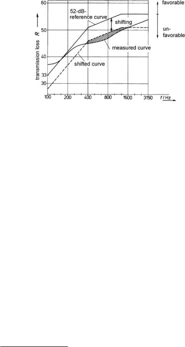
Fig. 13.13 Determination of the Weighted Sound-Reduction Index, ISO 140, or SoundTransmission Class, ASTM E90. The reference curve is considered between 100 Hz and 3150 Hz (ISO 140) or 125 Hz and 4000 Hz (ASTM E90)
13.6 Insulation of Vibrations
Insulation of structure-borne sound often turns out to be difficult in practice. On the one hand, materials like steel or concrete have only very low damping coefficients for structure-borne sound waves. On the other hand, it is often impossible to construct adequate insulation measures like soft, resilient inlays in optimal positions. For these reasons, it is best to take care of preventing structure-borne sound from entering structures like buildings, vehicles, and engines in the first place. Directly insulating the vibration source reduces this undesired effect, usually accomplished by providing an elastic support for the source. We now elaborate on how elastic support works acoustically.
Since sources of structure-borne sound are usually small compared to the wavelengths of structure-borne sound waves, we illustrate the fundamental principle of vibration insulation with concentrated elements. Further, we restrict ourselves to an example with only one degree of freedom. If there are more degrees of freedom involved, comparable measures are taken for each of them.
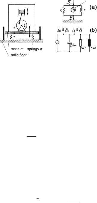
The example with a single-mass vibrator pictured in Fig. 13.14 is known as the engine-support problem. The figure shows a sketch of the situation and a mechaniccircuit diagram with an equivalent electric circuit of the 1st-kind analogy.
In our example, we is assume that the exciting force, F 0, is a constant sinusoidal force.3 The task at this point is to tune the system in such a way that the force draining
3 Alternatively, a constant velocity, v 0, could be assumed.
218 |
13 Insulation of Airand Structure-Borne Sound |
Fig. 13.14 Insulation of a single-mass vibrator—illustration of the situation and equivalent circuits
(a) Mechanic equvalent. (b) Electric equivalent
into the ground, F 1, is minimized. To this end, an Insulation Index, RI, is defined as follows,
|
|
|
|
RI |
= |
|
|
F |
1 |
|
|
|
|
|
|
(13.34) |
||||
|
|
|
|
|
|
20 lg |
F |
0 |
. |
|
|
|
|
|
||||||
|
|
|
|
|
|
|
|
|
|
|
|
|
|
|
|
|
|
|
|
|
|
|
|
|
|
|
|
|
|
|
|
|
|
|
|
|
|
|
|
|
|
After a short calculation—based on Fig. 13.14—one gets |
|
|
|
|||||||||||||||||
|
|
|
|
|
|
|
|
|
|
|
|
|
1 |
|
|
|
|
|
|
|
|
|
F 0 |
|
r + j ω m + |
|
|
|
|
|
|
|
|||||||||
|
|
= |
j ω n |
. |
|
|
(13.35) |
|||||||||||||
|
|
F |
|
|
|
|
|
|
1 |
|
|
|
|
|
|
|||||
|
|
|
|
1 |
|
|
|
|
|
r + |
j ω n |
|
|
|
|
|
|
|
|
|
and, with |
|
|
|
|
|
|
|
|
|
|
|
|
|
|
|
|
|
|||
1 |
|
|
|
|
|
|
|
|
ω0 m |
|
= |
ω0 |
|
|
||||||
ω0 = |
√ |
|
and |
Q = |
|
|
|
|
|
, |
(13.36) |
|||||||||
|
|
r |
|
ω |
||||||||||||||||
m n |
|
|
||||||||||||||||||
where ω = r/m is the (angular) frequency bandwidth, we obtain the following expression,
|
|
|
|
|
|
ω 2 |
+ |
Q2 |
ω |
|
|
2 |
1 |
2 |
|
|
|
||
|
|
|
|
|
|
ω0 |
|
ω0 |
|
− |
|
|
|
|
|
||||
|
|
|
|
|
|
|
|
|
|
|
|
|
|
||||||
|
= |
|
|
|
|
|
|
|
ω |
|
|
2 |
|
|
|
|
|
||
RI |
|
20 lg |
|
|
|
|
|
|
2 |
Q |
|
|
|
|
|
dB . |
(13.37) |
||
|
|
|
|
|
|
|
|
|
ω0 |
|
|
|
|
|
|
|
|||
|
|
|
|
|
|
|
|
|
|
+ |
|
|
|
|
|
|
|
|
|
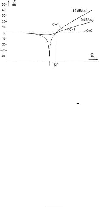
Figure 13.15 presents a plot of this function for various values of the quality factor, Q. Asymptotic values for the slopes of the curves are as follows.
–Q > 1 After the vanishing√damping at ω0/ω = 1 the damping becomes positive beyond ω0/ω = 2 (13.37). By dividing by Q2 and neglecting
tiny members of the sums, we get RI 20 lg (ω/ω0)4 ω2. This means that the slope approximates 12 dB/oct.
13.6 Insulation of Vibrations |
219 |
Fig. 13.15 Transmission loss of a single-mass vibrator as a function of frequency
– Q = 1 This is a reasonably-damped oscillating
sum |
√ |
|
|
I |
|
( |
ω |
/ |
ω0 |
)2 |
members again, we get R |
|
20 lg |
|
|
||||||
ω0/ω = |
|
2 |
is 6 dB/oct. |
|
|
|
|
|
|
|
case. Neglecting smallω. The slope, beyond
√
Note that RI only becomes positive for values of ω/ω0 > 2. To insulate a source of structure-borne sound, the support must therefore be tuned to a resonance frequency well below the operating frequency, which is usually the frequency of the exciting force. This technique is called low-end tuning. Usually one aims for a frequency ratio of 1/5–1/10.
The insulation index decreases with increased damping of the system because the damping acts as a sound bridge. However, moderate damping is still important because it limits the “dancing” effect experienced by vibrating system at the resonance frequency or close to it. This dancing effect also occurs when a rotating engine starts up and runs slowly through the resonance point of the support. It is thus wise to limit the movement at these frequencies with properly adjusted dashpots or even hard mechanic boundaries.
Many types of elastic elements are available used for vibration insulation, including steel springs, rubber-metal-compound elements, rubber, and synthetic-foam plates. Progressive spring characteristics like those provided by rubber help avoiding dancing of the source.
If the elastic element in use is known to have a linear characteristic, the resonance frequency, ω0, is determinable from the amount, x , that the element compresses under a load. This is a handy on-site check of whether the right elastic elements have been installed or if there are accidental sound bridges. The relevant formula is
f0 |
≈ |
√ |
|
5 |
|
, |
(13.38) |
Hz |
|
|
|
||||
x |
/cm |
220 |
|
|
|
|
|
|
13 Insulation of Airand Structure-Borne Sound |
||||
with |
|
|
|
|
|
|
|
|
|
|
|
ω0 = |
1 |
|
n = |
x0 |
|
and applying F = m · 9.81 |
m |
|
|||
√ |
|
, |
|
, |
|
. |
(13.39) |
||||
F |
s2 |
||||||||||
m n |
|||||||||||
When a sound-insulation increase of 12 dB/oct is not sufficient, multi-layer supports are be applied. In terms of transmission theory, this technique is equivalent to low-pass filters of higher order. Vibrations at distinct frequencies are further reduced with tuned resonating absorbers, also called vibration extinctors—for details see the solution for Problem 13.4.
The reciprocal nature of vibration insulation enables its usage in protecting equipment that would be impaired by vibration, like fine-weighing scales or electron microscopes. One possible technique is to place sensitive equipment on a heavy table supported by air cushions.
13.7 Insulation of Floors with Regard to Impact Sounds
In architectural acoustics tapping sound, that is, structure-borne sound excited by walking on floors (footfall), is of particular relevance. Such sound is transmitted to adjacent rooms, especially below the floor, and then radiated as airborne sound. This effect also holds for other approximately point-wise sources of excitation like knocking, falling items, pushed chairs, or household appliances.
Insulation against this kind of sound are accomplished with resilient floor coverings, such as carpets, plastics layers, or wooden plates, under-packed with a compliant layer. We estimate the achieved insulation in the same manner as described earlier. The quantity used as “mass” in such an estimation is that part of the total source mass that is in direct contact with the floor, and the value used as compliance is the one given by the contact area.
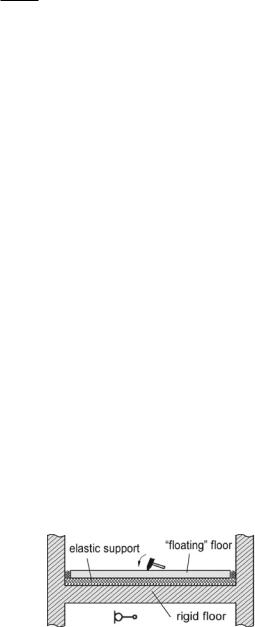
The floating or resilient floor is another efficient method for reducing tapping sounds. As sketched in Fig. 13.16, such a floor consists of a load-distributing plate, possibly made of cast concrete, supported by a compliant layer, usually made of mineral wool or synthetic elastic foam.
Fig. 13.16 Floating-floor construction for insulation against tapping sounds