

11.6 Resonance Absorbers |
179 |
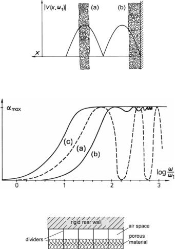
Fig. 11.9 Placements of layers of porous material in front of a hard wall. (a) With air-gap.
(b) Directly on the wall
Fig. 11.10 Absorption of porous material as a function of frequency. (a) Finite layer with air-gap.
(b) Finite layer directly on wall. (c) Infinite thickness
Fig. 11.11 Porous absorber in a cassette structure
11.6 Resonance Absorbers
As shown above, when using absorbent materials the effective layer must be placed a quarter wavelength, λ/4, in front of the wall. For a 100-Hz frequency with a wavelength of 3.4 m, for instance, this means placement of 85 cm in front of walls. In practice, so much space is usually not available.
Especially for low frequencies, that is, for so-called bass traps, a different absorber principle is employed, which is based on resonance absorption. To this end, the absorbent wall is covered with acoustic resonators, the input impedance of which is
180 |
11 Dissipation, Reflection, Refraction, and Absorption |
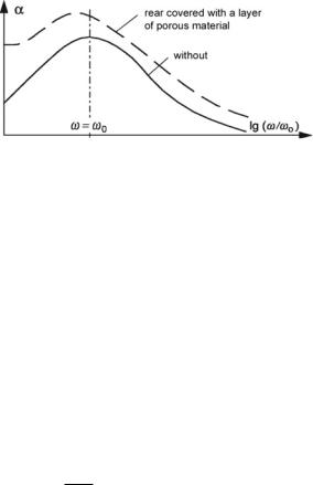
Fig. 11.12 Absorption of resonance absorbers as a function of frequency
low at their resonance frequency. Such resonators gain from efficient positioning—in enclosed spaces preferably in edges and corners.
The principle frequency relationship of α for resonance absorbers is plotted in Fig. 11.12, both with and without additional porous material.
Technical data for diffuse sound incidence are available from the literature or directly from the suppliers. In the following, we only present fundamental concepts. Three basic types of resonance absorbers are available, Helmholtz absorbers, membrane absorbers, and micro-perforated panel absorbers. These types also exist in combined and/or integrated form.
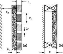
Helmholtz Absorbers
Plates with holes or slits in them are placed at a distance from a wall. Absorbent materials is often put on the rear side of the plates. Figure 11.13a illustrates the arrangement. For the wall impedance we get
|
|
|
|
|
p |
|
|
1 |
|
|
|
|||
|
Z wall |
= |
|
|
→ |
|
= Z a A = j ω m |
+ |
|
+ r , |
|
(11.38) |
||
|
|
v |
|
|||||||||||
|
|
|
j ω n |
|
||||||||||
|
|
|
|
|
|
|
→ |
|
|
|
|
|
|
|
where r = Ξ b1 is the area-specific resistance, |
n = κ b2 the area-specific com- |
|||||||||||||
pliance, and m |
= |
|
3 |
+ |
η) |
σ the area-specific mass. Thereby, σ |
= |
4 |
||||||
|
(b |
|
|
|
π r2/b2 is the |
|||||||||
perforation rate |
(porosity), and η is a correction factor (mouth correction) consider- |
|||||||||||||
ing that at the mouth of a hole or slit more air mass is moved than is actually inside the mouth. An estimate for circular holes is η = 1.6 r.
Membrane Absorbers
These absorbers possess co-vibrating membranes—such as plates, foils, or other mass-afflicted materials—in front of an air-gap before a wall. To decrease their resonance frequencies, the membranes are sometimes loaded with additional weight. Absorbent material is used to partly or completely fill the air-space. The arrangement is depicted in Fig. 11.13b. Numerous different built forms exist, including such with more than one membrane layer.
11.6 Resonance Absorbers |
181 |
Fig. 11.13 Resonance absorbers. (a) Helmholtz absorber. (b) Membrane absorber
Although bending waves of the membranes are certainly possible, for rough calculations, we usually assume wall-perpendicular movements only. The reason for this assumption is that reacting forces due to bending of the material are usually negligible compared to those due to the stiffness of the air cushion. m is the area-specific mass of the plate, and n = κ b is its compliance. The area specific resistance, r , is hard to estimate. It contains losses within the plate.
Micro-perforated Panel Absorbers
A special kind of panel absorbers uses micro-perforated panels. These absorbers incorporate perforated thin panels or foils in front of an air-gap before a rigid wall, similar to what Fig. 11.13a shows, but without absorbent materials on the rear side of the panel. The perforations in the thin panel or foil are in the sub-millimeter range (diameter 0.1–1 mm) to provide high acoustic resistance but low area-specific acoustic-mass reactance. This low mass reactance is necessary for broadband absorbers. Besides the micro-perforated panels or foils, no further absorbent material is required.
Micro-perforated panel absorbers are of the resonant type. Single-panel absorbers have bandwidth as wide as 1–2 octaves. Two different resonant frequencies about 20% apart, realizable with double-layered micro-perforated panels, allow for even broader absorption bandwidths. Yet, the most intriguing feature is that microperforated panel absorbers are producible from a great variety of panel or foil materials, including thin metal sheets and flexible and/or translucent foils.

182 |
11 Dissipation, Reflection, Refraction, and Absorption |
11.7 Exercises
Dissipation, Reflection, Refraction, and Absorption
Problem 11.1 Using the updated Euler equation and the continuity equation (11.13) for porous media,
(a) Derive the second-order wave equation |
|
||||||||||||
|
∂2 p |
|
|||||||||||
|
|
|
|
− ( j ω + σ Ξ )( j ω κ) |
p |
= 0. |
(11.39) |
||||||
|
|||||||||||||
|
∂ x |
2 |
|
||||||||||
|
|
|
|
||||||||||
(b) Show that the characteristic (field) impedance is |
|
||||||||||||
|
|
|
|
|
|
p |
|
|
|
||||
|
|
|
|
|
|
|
|
||||||
|
|
Z c = |
|
|
i → |
= eq(ω) K , |
(11.40) |
||||||
|
|
|
v |
||||||||||
|
|
|
|
|
|
|
i → |
|
|||||
with K = 1/κ and eq(ω) being the equivalent dynamic density of the porous media—see (11.17)].
Problem 11.2 A K undt’s tube is considered lossy, that is, with a complex propagation coefficient, γ = α + j β.
How do losses influence the standing waves and, therefore, the measurement results concerning the envelope’s maximum and minimum values and the standing wave ratio, given that the standing-wave-ratio method is applied?
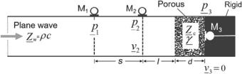
Problem 11.3 A K undt’s tube is lossless with air as the medium, similar to Fig. 7.8, and the specimen under test is a piece of porous material with a thickness, d, which is appropriately fitted in the tube end with a rigid backing. In addition to two microphone positions, M1, M2, in front of the material surface, a further microphone, M3, is placed in the rigid backing right on the back surface of the porous material as shown in Fig. 11.14.
Determine the complex-valued propagation coefficient, γ, and the characteristic impedance, Z c, of the porous material.
Problem 11.4 A sound wave is incident with an angle of θ1 upon a boundary between two different media, Z 1, β1 and Z 2, β2.
Determine the reflected and transmitted waves. Express the reflectance (reflection coefficient) and the absorption coefficient.
What conditions lead to maximum absorption?
11.7 Exercises |
183 |
Fig. 11.14 Three microphone method in Kundt’s tube for characterizing the porous materials
Problem 11.5 Discuss the angular dependence of the degree of absorption, α, of a wall based on the ratio | Z wall|/Zw, air .
Chapter 12
Geometric Acoustics and Diffuse Sound
Fields
So far in this book, we dealt with sound propagation on the basis of the wave equation. However, this approach becomes difficult when treating sound fields inside rooms with complicated shapes like concert halls or churches. An approximate method called geometrical acoustics is useful in these cases.
This method considers sound propagation in terms of so-called sound rays. We introduced sound rays already in Sect. 10.5, where a ray icon designates the wave bundle that emerges from a circular hole in a rigid wall when R λ. The idea is that the wave bundle propagates along a straight line like a ray of light.
The concept of rays is mathematically defined as the limiting case of maintaining plane areas of constant phase and letting the wavelength go to zero. In practice, rays serve to approximate propagating waves under the following two conditions. The wavelength is small compared to the linear dimensions of boundary areas and obstacles. Diffraction and interference are negligibly.
The energy density, W , within a ray is equal to the energy density in a plane propagating wave. To compute its amount, we consider a wave bundle propagating through an area of 1 m2 for 1 m—see Fig. 12.1 for illustration. The energy density, then, is the active power, P, times the traveling time, t1 = (1/c) · 1 m, divided by the volume of 1 m3—or, in mathematical terms,
W |
|
|
|
I |
|
1 m2 |
|
1 |
|
|
1 m |
1 |
|
|
|
| |
−→ |
| |
|
, |
(12.1) |
||||||||||
|
|
−→ |
|
|
|
|
|
|
|
|
|
|
|
|
|
|
|
|
|
|
|
|
|||||||||
|
|
= | | · |
|
|
|
|
|
· |
|
|
|
|
|
= |
|
|
I |
|
= |
I |
|
|
|||||||||
|
ray |
|
|
|
|
|
|
c |
|
|
|
1 m |
3 |
|
|
|
c |
|
c |
|
|||||||||||
|
|
|
|
|
|
|
|
|
|
|
|
|
|
|
|
|
|
|
|
|
|
|
|
||||||||
|
|
|
|
|
|
|
|
|
|
|
|
|
|
|
|
|
|
|
|
|
|
|
|
||||||||
|
|
|
|
|
|
P |
|
|
|
|
|
|
|
|
|
t1 |
|
V −1 |
|
|
|
|
|
|
|
|
|
||||
|
|
|
|
|
|
|
|
|
|
|
|
|
|
|
|
|
|
|
|
|
|
|
|
||||||||
W
−→
where I is the sound-intensity vector, and I is the magnitude of the averaged sound intensity.
© Springer-Verlag GmbH Germany, part of Springer Nature 2021 |
185 |
N. Xiang and J. Blauert, Acoustics for Engineers, https://doi.org/10.1007/978-3-662-63342-7_12