

90 6 Electric-Field Transducers
6.6 Dielectric Sound Emitters and Receivers
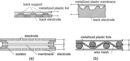
Dielectric sound emitters are used as loudspeakers, especially tweeters, and as ultrasound emitters—see Fig. 6.15. When light, tightly stretched membranes are used, mechanic tuning to the high-frequency end is unavoidable but maybe compensated for with equalization in the electric circuit.
Since the membrane experiences only tiny displacements, large areas that move in phase are necessary for efficient sound emission. The efficiency increases proportional to polarization-voltage square, but high voltages carry the danger of electric burn-throughs. Fortunately, there are self-healing membrane materials. Various shapes are possible, including large planes and spheres, whereby wire meshes are in use for the back electrodes. Loudspeakers have been built with a frequency range down to 50 Hz using this principle. Figure 6.16 shows two realized push-pull arrangement. There are also dielectric (electrostatic) headphones, which are known for their particularly “clear” presentation. This auditory clearness, which also holds for electrostatic loudspeakers, is attributed to their tiny moving masses, which do not cause any severe phase distortions.
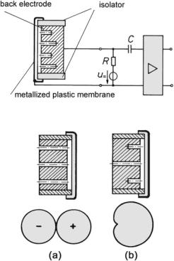
Dielectric sound receivers are known as condenser microphones. They have a broad frequency range and only minimal distortions, making a high-quality condenser microphone a good choice for studio and measuring applications. Figure 6.17 presents a schematic section of such a microphone. The air-gap behind the membrane is typically 5–100 μm, and capsule capacitances are 20–100 pF for studio and measuring microphones. The membranes are usually gold-coated plastic foils. Polarization voltages are 40–200 V. The losses of the capsule capacitance are minimal, represented by a so-called charge resistance as high as 0.5–300 G . Due to the high inner impedance, the connecting wires are prone to induce noise, such as humming. Further, they add a parasitic capacitance and may cause mechanical
Fig. 6.15 Examples of dielectric sound emitter constructions
Fig. 6.16 Electrostatic loudspeaker with push/pull driving forces. (a) Arrangement as used in high-quality loudspeaker. (b) Arrangement as, for example, used in spherical loudspeakers
6.6 Dielectric Sound Emitters and Receivers |
91 |
Fig. 6.17 Condenser microphone with accompanying electric circuit
Fig. 6.18 Figure-of-eight or cardioid microphone
problems. To avoid such issues, there is often an impedance-converting amplifier positioned back-to-back with the capsule. After this stage, typical sensitivities are about Tup ≈ 10–30 mV/Pa.
Condenser microphones, when driven in a so-called low-frequency circuit— shown in Fig. 6.17—have, on principle, a low-end roll-off that is determined by the first-order R/C high-pass formed by the capsule capacitance and the charge resistance.
An alternative method of operating dielectric microphones, the so-called highfrequency circuit, avoids this high-pass behavior. Here, due to their varying capacitance, condenser microphones are integrated into electric-oscillator circuits as frequency-determining elements. However, in this mode, the condenser microphones no longer act as reversible transducers but as controlled couplers. The principle is applied for measurement microphones because it is extremely resistant to induced noise. Also, as it does not have a lower cut-off frequency, you can even measure the static air pressure with it!
Condenser microphones are elongation transducers. As pressure receivers they are high-end tuned, and as figure-of-eight or cardioid microphones—such as shown in Fig. 6.18—they are low-end tuned with prominent damping.
92 |
6 Electric-Field Transducers |
Fig. 6.19 Microphone with a steerable directional characteristic. (a) Spherical. (b) Wide-angle cardioid. (c) Cardioid. (d) Super cardiod. (e) Figure-of-eight
Fig. 6.20 Silicon-chip microphone (schematic)
High symmetry of the figure-of-eight directional characteristic is achieved by placing a counter electrode on the other side of the capsule. This detail also allows the directional characteristic to be steered electrically since the sensitivities of the membranes are controlled by the applied polarization voltages. Figure 6.19 provides an overview.
Miniature dielectric microphones, MEMS, are manufactured very much like electronic chips, for instance, by etching little membranes with an air-gap into the substrate of silicon wafers. This process leads to silicon-chip microphones— schematically shown in Fig. 6.20. Due to their very small dimensions, MEMS microphones are easily arranged in arrays. Both during the production process and the actual use, these microphones withstand fairly high temperatures.
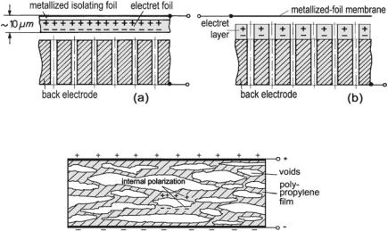
In a similar way as magnetization is achieved with magnets, polarization is achieved with so-called electrets. These are materials that show a permanent polarization after appropriate treatment, such as exposure of heated material to strong electric fields and subsequent down-cooling, corona discharge, or other forms of electron bombardment. If such a material, for example, teflon or fluorocarbon, is positioned behind the membrane, an external polarization voltage becomes superfluous. These electrets easily mimic polarization voltages of 100 V. Figure 6.21 illustrates the principle.
Electret microphones, including an integrated impedance converter, are manufactured very economically and have become a widespread microphone type worldwide.
6.6 Dielectric Sound Emitters and Receivers |
93 |
Fig. 6.21 Electret microphones. (a) Version with electret membrane. (b) Version with electret back electrode
Fig. 6.22 Piezoelectret film
Recently, elastic electrets have become available. An example would be piezoelectric polymer films, made from polyethylene. They are extruded and treated mechanically afterward in such a way that they develop a cellular structure with ample void bubbles in it—sketched in Fig. 6.22. Polarization is performed by corona discharge with the effect that surface polarization develops around the voids. These so-called piezoelectrets behave very much like piezoelectric material—see Table 6.1 for comparison. Piezoelectret films, coated with conducting layers, act as microphones without additional attachments. Stacked ≈50 μm layers of these films achieve sensitivities of ≥20 mV/Pa.
6.7 Further Transducer and Coupler Principles
In addition to the transducer principles that we already discussed in the current and prior sections, there are some further techniques, even without magnetic and electric fields, that we like to mention briefly.
The first bases on the fact that a wire with a varying current passing through it heats up, causes variations of the air pressure around it, and radiates sound. This is called a thermophone. The wire resistance also varies in response to the varying velocity of airflow, making it useful as a velocity receiver. Such a device is called a hot-wire anemometer. Modern constructions employ micro-machined sensors with two very thin, heated wires. These cover a frequency range from 0 Hz up to more than 20 kHz.