
- •Contents
- •Acknowledgments
- •Preface
- •What a Crossover Does
- •Why a Crossover Is Necessary
- •Beaming and Lobing
- •Passive Crossovers
- •Active Crossover Applications
- •Bi-Amping and Bi-Wiring
- •Loudspeaker Cables
- •The Advantages and Disadvantages of Active Crossovers
- •The Advantages of Active Crossovers
- •Some Illusory Advantages of Active Crossovers
- •The Disadvantages of Active Crossovers
- •The Next Step in Hi-Fi
- •Active Crossover Systems
- •Matching Crossovers and Loudspeakers
- •A Modest Proposal: Popularising Active Crossovers
- •Multi-Way Connectors
- •Subjectivism
- •Sealed-Box Loudspeakers
- •Reflex (Ported) Loudspeakers
- •Auxiliary Bass Radiator (ABR) Loudspeakers
- •Transmission Line Loudspeakers
- •Horn Loudspeakers
- •Electrostatic Loudspeakers
- •Ribbon Loudspeakers
- •Electromagnetic Planar Loudspeakers
- •Air-Motion Transformers
- •Plasma Arc Loudspeakers
- •The Rotary Woofer
- •MTM Tweeter-Mid Configurations (d’Appolito)
- •Vertical Line Arrays
- •Line Array Amplitude Tapering
- •Line Array Frequency Tapering
- •CBT Line Arrays
- •Diffraction
- •Sound Absorption in Air
- •Modulation Distortion
- •Drive Unit Distortion
- •Doppler Distortion
- •Further Reading on Loudspeaker Design
- •General Crossover Requirements
- •1 Adequate Flatness of Summed Amplitude/Frequency Response On-Axis
- •2 Sufficiently Steep Roll-Off Slopes Between the Filter Outputs
- •3 Acceptable Polar Response
- •4 Acceptable Phase Response
- •5 Acceptable Group Delay Behaviour
- •Further Requirements for Active Crossovers
- •1 Negligible Extra Noise
- •2 Negligible Impairment of System Headroom
- •3 Negligible Extra Distortion
- •4 Negligible Impairment of Frequency Response
- •5 Negligible Impairment of Reliability
- •Linear Phase
- •Minimum Phase
- •Absolute Phase
- •Phase Perception
- •Target Functions
- •All-Pole and Non-All-Pole Crossovers
- •Symmetric and Asymmetric Crossovers
- •Allpass and Constant-Power Crossovers
- •Constant-Voltage Crossovers
- •First-Order Crossovers
- •First-Order Solen Split Crossover
- •First-Order Crossovers: 3-Way
- •Second-Order Crossovers
- •Second-Order Butterworth Crossover
- •Second-Order Linkwitz-Riley Crossover
- •Second-Order Bessel Crossover
- •Second-Order 1.0 dB-Chebyshev Crossover
- •Third-Order Crossovers
- •Third-Order Butterworth Crossover
- •Third-Order Linkwitz-Riley Crossover
- •Third-Order Bessel Crossover
- •Third-Order 1.0 dB-Chebyshev Crossover
- •Fourth-Order Crossovers
- •Fourth-Order Butterworth Crossover
- •Fourth-Order Linkwitz-Riley Crossover
- •Fourth-Order Bessel Crossover
- •Fourth-Order 1.0 dB-Chebyshev Crossover
- •Fourth-Order Linear-Phase Crossover
- •Fourth-Order Gaussian Crossover
- •Fourth-Order Legendre Crossover
- •Higher-Order Crossovers
- •Determining Frequency Offsets
- •Filler-Driver Crossovers
- •The Duelund Crossover
- •Crossover Topology
- •Crossover Conclusions
- •Elliptical Filter Crossovers
- •Neville Thiele MethodTM (NTM) Crossovers
- •Subtractive Crossovers
- •First-Order Subtractive Crossovers
- •Second-Order Butterworth Subtractive Crossovers
- •Third-Order Butterworth Subtractive Crossovers
- •Fourth-Order Butterworth Subtractive Crossovers
- •Subtractive Crossovers With Time Delays
- •Performing the Subtraction
- •Active Filters
- •Lowpass Filters
- •Highpass Filters
- •Bandpass Filters
- •Notch Filters
- •Allpass Filters
- •All-Stop Filters
- •Brickwall Filters
- •The Order of a Filter
- •Filter Cutoff Frequencies and Characteristic Frequencies
- •First-Order Filters
- •Second-Order and Higher-Order Filters
- •Filter Characteristics
- •Amplitude Peaking and Q
- •Butterworth Filters
- •Linkwitz-Riley Filters
- •Bessel Filters
- •Chebyshev Filters
- •1 dB-Chebyshev Lowpass Filter
- •3 dB-Chebyshev Lowpass Filter
- •Higher-Order Filters
- •Butterworth Filters up to 8th-Order
- •Linkwitz-Riley Filters up to 8th-Order
- •Bessel Filters up to 8th-Order
- •Chebyshev Filters up to 8th-Order
- •More Complex Filters—Adding Zeros
- •Inverse Chebyshev Filters (Chebyshev Type II)
- •Elliptical Filters (Cauer Filters)
- •Some Lesser-Known Filter Characteristics
- •Transitional Filters
- •Linear-Phase Filters
- •Gaussian Filters
- •Legendre-Papoulis Filters
- •Laguerre Filters
- •Synchronous Filters
- •Other Filter Characteristics
- •Designing Real Filters
- •Component Sensitivity
- •First-Order Lowpass Filters
- •Second-Order Filters
- •Sallen & Key 2nd-Order Lowpass Filters
- •Sallen & Key Lowpass Filter Components
- •Sallen & Key 2nd-Order Lowpass: Unity Gain
- •Sallen & Key 2nd-Order Lowpass Unity Gain: Component Sensitivity
- •Filter Frequency Scaling
- •Sallen & Key 2nd-Order Lowpass: Equal Capacitor
- •Sallen & Key 2nd-Order Lowpass Equal-C: Component Sensitivity
- •Sallen & Key 2nd-Order Butterworth Lowpass: Defined Gains
- •Sallen & Key 2nd-Order Lowpass: Non-Equal Resistors
- •Sallen & Key 2nd-Order Lowpass: Optimisation
- •Sallen & Key 3rd-Order Lowpass: Two Stages
- •Sallen & Key 3rd-Order Lowpass: Single Stage
- •Sallen & Key 4th-Order Lowpass: Two Stages
- •Sallen & Key 4th-Order Lowpass: Single-Stage Butterworth
- •Sallen & Key 4th-Order Lowpass: Single-Stage Linkwitz-Riley
- •Sallen & Key 5th-Order Lowpass: Three Stages
- •Sallen & Key 5th-Order Lowpass: Two Stages
- •Sallen & Key 5th-Order Lowpass: Single Stage
- •Sallen & Key 6th-Order Lowpass: Three Stages
- •Sallen & Key 6th-Order Lowpass: Single Stage
- •Sallen & Key Lowpass: Input Impedance
- •Linkwitz-Riley Lowpass With Sallen & Key Filters: Loading Effects
- •Lowpass Filters With Attenuation
- •Bandwidth Definition Filters
- •Bandwidth Definition: Butterworth Versus Bessel
- •Variable-Frequency Lowpass Filters: Sallen & Key
- •First-Order Highpass Filters
- •Sallen & Key 2nd-Order Filters
- •Sallen & Key 2nd-Order Highpass Filters
- •Sallen & Key Highpass Filter Components
- •Sallen & Key 2nd-Order Highpass: Unity Gain
- •Sallen & Key 2nd-Order Highpass: Equal Resistors
- •Sallen & Key 2nd-Order Butterworth Highpass: Defined Gains
- •Sallen & Key 2nd-Order Highpass: Non-Equal Capacitors
- •Sallen & Key 3rd-Order Highpass: Two Stages
- •Sallen & Key 3rd-Order Highpass in a Single Stage
- •Sallen & Key 4th-Order Highpass: Two Stages
- •Sallen & Key 4th-Order Highpass: Butterworth in a Single Stage
- •Sallen & Key 4th-Order Highpass: Linkwitz-Riley in a Single Stage
- •Sallen & Key 4th-Order Highpass: Single-Stage With Other Filter Characteristics
- •Sallen & Key 5th-Order Highpass: Three Stages
- •Sallen & Key 5th-Order Butterworth Filter: Two Stages
- •Sallen & Key 5th-Order Highpass: Single Stage
- •Sallen & Key 6th-Order Highpass: Three Stages
- •Sallen & Key 6th-Order Highpass: Single Stage
- •Sallen & Key Highpass: Input Impedance
- •Bandwidth Definition Filters
- •Bandwidth Definition: Subsonic Filters
- •Bandwidth Definition: Combined Ultrasonic and Subsonic Filters
- •Variable-Frequency Highpass Filters: Sallen & Key
- •Designing Filters
- •Multiple-Feedback Filters
- •Multiple-Feedback 2nd-Order Lowpass Filters
- •Multiple-Feedback 2nd-Order Highpass Filters
- •Multiple-Feedback 3rd-Order Filters
- •Multiple-Feedback 3rd-Order Lowpass Filters
- •Multiple-Feedback 3rd-Order Highpass Filters
- •Biquad Filters
- •Akerberg-Mossberg Lowpass Filter
- •Akerberg-Mossberg Highpass Filters
- •Tow-Thomas Biquad Lowpass and Bandpass Filter
- •Tow-Thomas Biquad Notch and Allpass Responses
- •Tow-Thomas Biquad Highpass Filter
- •State-Variable Filters
- •Variable-Frequency Filters: State-Variable 2nd Order
- •Variable-Frequency Filters: State-Variable 4th-Order
- •Variable-Frequency Filters: Other Orders of State-Variable
- •Other Filters
- •Aspects of Filter Performance: Noise and Distortion
- •Distortion in Active Filters
- •Distortion in Sallen & Key Filters: Looking for DAF
- •Distortion in Sallen & Key Filters: 2nd-Order Lowpass
- •Distortion in Sallen & Key Filters: 2nd-Order Highpass
- •Mixed Capacitors in Low-Distortion 2nd-Order Sallen & Key Filters
- •Distortion in Sallen & Key Filters: 3rd-Order Lowpass Single Stage
- •Distortion in Sallen & Key Filters: 3rd-Order Highpass Single Stage
- •Distortion in Sallen & Key Filters: 4th-Order Lowpass Single Stage
- •Distortion in Sallen & Key Filters: 4th-Order Highpass Single Stage
- •Distortion in Sallen & Key Filters: Simulations
- •Distortion in Sallen & Key Filters: Capacitor Conclusions
- •Distortion in Multiple-Feedback Filters: 2nd-Order Lowpass
- •Distortion in Multiple-Feedback Filters: 2nd-Order Highpass
- •Distortion in Tow-Thomas Filters: 2nd-Order Lowpass
- •Distortion in Tow-Thomas Filters: 2nd-Order Highpass
- •Noise in Active Filters
- •Noise and Bandwidth
- •Noise in Sallen & Key Filters: 2nd-Order Lowpass
- •Noise in Sallen & Key Filters: 2nd-Order Highpass
- •Noise in Sallen & Key Filters: 3rd-Order Lowpass Single Stage
- •Noise in Sallen & Key Filters: 3rd-Order Highpass Single Stage
- •Noise in Sallen & Key Filters: 4th-Order Lowpass Single Stage
- •Noise in Sallen & Key Filters: 4th-Order Highpass Single Stage
- •Noise in Multiple-Feedback Filters: 2nd-Order Lowpass
- •Noise in Multiple-Feedback Filters: 2nd-Order Highpass
- •Noise in Tow-Thomas Filters
- •Multiple-Feedback Bandpass Filters
- •High-Q Bandpass Filters
- •Notch Filters
- •The Twin-T Notch Filter
- •The 1-Bandpass Notch Filter
- •The Bainter Notch Filter
- •Bainter Notch Filter Design
- •Bainter Notch Filter Example
- •An Elliptical Filter Using a Bainter Highpass Notch
- •The Bridged-Differentiator Notch Filter
- •Boctor Notch Filters
- •Other Notch Filters
- •Simulating Notch Filters
- •The Requirement for Delay Compensation
- •Calculating the Required Delays
- •Signal Summation
- •Physical Methods of Delay Compensation
- •Delay Filter Technology
- •Sample Crossover and Delay Filter Specification
- •Allpass Filters in General
- •First-Order Allpass Filters
- •Distortion and Noise in 1st-Order Allpass Filters
- •Cascaded 1st-Order Allpass Filters
- •Second-Order Allpass Filters
- •Distortion and Noise in 2nd-Order Allpass Filters
- •Third-Order Allpass Filters
- •Distortion and Noise in 3rd-Order Allpass Filters
- •Higher-Order Allpass Filters
- •Delay Lines for Subtractive Crossovers
- •Variable Allpass Time Delays
- •Lowpass Filters for Time Delays
- •The Need for Equalisation
- •What Equalisation Can and Can’t Do
- •Loudspeaker Equalisation
- •1 Drive Unit Equalisation
- •3 Bass Response Extension
- •4 Diffraction Compensation Equalisation
- •5 Room Interaction Correction
- •Equalisation Circuits
- •HF-Cut and LF-Boost Equaliser
- •Combined HF-Boost and HF-Cut Equaliser
- •Adjustable Peak/Dip Equalisers: Fixed Frequency and Low Q
- •Adjustable Peak/Dip Equalisers With High Q
- •Parametric Equalisers
- •The Bridged-T Equaliser
- •The Biquad Equaliser
- •Capacitance Multiplication for the Biquad Equaliser
- •Equalisers With Non-Standard Slopes
- •Equalisers With −3 dB/Octave Slopes
- •Equalisers With −3 dB/Octave Slopes Over Limited Range
- •Equalisers With −4.5 dB/Octave Slopes
- •Equalisers With Other Slopes
- •Equalisation by Filter Frequency Offset
- •Equalisation by Adjusting All Filter Parameters
- •Component Values
- •Resistors
- •Through-Hole Resistors
- •Surface-Mount Resistors
- •Resistors: Values and Tolerances
- •Resistor Value Distributions
- •Obtaining Arbitrary Resistance Values
- •Other Resistor Combinations
- •Resistor Noise: Johnson and Excess Noise
- •Resistor Non-Linearity
- •Capacitors: Values and Tolerances
- •Obtaining Arbitrary Capacitance Values
- •Capacitor Shortcomings
- •Non-Electrolytic Capacitor Non-Linearity
- •Electrolytic Capacitor Non-Linearity
- •Active Devices for Active Crossovers
- •Opamp Types
- •Opamp Properties: Noise
- •Opamp Properties: Slew Rate
- •Opamp Properties: Common-Mode Range
- •Opamp Properties: Input Offset Voltage
- •Opamp Properties: Bias Current
- •Opamp Properties: Cost
- •Opamp Properties: Internal Distortion
- •Opamp Properties: Slew Rate Limiting Distortion
- •Opamp Properties: Distortion Due to Loading
- •Opamp Properties: Common-Mode Distortion
- •Opamps Surveyed
- •The TL072 Opamp
- •The NE5532 and 5534 Opamps
- •The 5532 With Shunt Feedback
- •5532 Output Loading in Shunt-Feedback Mode
- •The 5532 With Series Feedback
- •Common-Mode Distortion in the 5532
- •Reducing 5532 Distortion by Output Stage Biasing
- •Which 5532?
- •The 5534 Opamp
- •The LM4562 Opamp
- •Common-Mode Distortion in the LM4562
- •The LME49990 Opamp
- •Common-Mode Distortion in the LME49990
- •The AD797 Opamp
- •Common-Mode Distortion in the AD797
- •The OP27 Opamp
- •Opamp Selection
- •Crossover Features
- •Input Level Controls
- •Subsonic Filters
- •Ultrasonic Filters
- •Output Level Trims
- •Output Mute Switches, Output Phase-Reverse Switches
- •Control Protection
- •Features Usually Absent
- •Metering
- •Relay Output Muting
- •Switchable Crossover Modes
- •Noise, Headroom, and Internal Levels
- •Circuit Noise and Low-Impedance Design
- •Using Raised Internal Levels
- •Placing the Output Attenuator
- •Gain Structures
- •Noise Gain
- •Active Gain Controls
- •Filter Order in the Signal Path
- •Output Level Controls
- •Mute Switches
- •Phase-Invert Switches
- •Distributed Peak Detection
- •Power Amplifier Considerations
- •Subwoofer Applications
- •Subwoofer Technologies
- •Sealed-Box (Infinite Baffle) Subwoofers
- •Reflex (Ported) Subwoofers
- •Auxiliary Bass Radiator (ABR) Subwoofers
- •Transmission Line Subwoofers
- •Bandpass Subwoofers
- •Isobaric Subwoofers
- •Dipole Subwoofers
- •Horn-Loaded Subwoofers
- •Subwoofer Drive Units
- •Hi-Fi Subwoofers
- •Home Entertainment Subwoofers
- •Low-Level Inputs (Unbalanced)
- •Low-Level Inputs (Balanced)
- •High-Level Inputs
- •High-Level Outputs
- •Mono Summing
- •LFE Input
- •Level Control
- •Crossover In/Out Switch
- •Crossover Frequency Control (Lowpass Filter)
- •Highpass Subsonic Filter
- •Phase Switch (Normal/Inverted)
- •Variable Phase Control
- •Signal Activation Out of Standby
- •Home Entertainment Crossovers
- •Fixed Frequency
- •Variable Frequency
- •Multiple Variable
- •Power Amplifiers for Home Entertainment Subwoofers
- •Subwoofer Integration
- •Sound-Reinforcement Subwoofers
- •Line or Area Arrays
- •Cardioid Subwoofer Arrays
- •Aux-Fed Subwoofers
- •Automotive Audio Subwoofers
- •Motional Feedback Loudspeakers
- •History
- •Feedback of Position
- •Feedback of Velocity
- •Feedback of Acceleration
- •Other MFB Speakers
- •Published Projects
- •Conclusions
- •External Signal Levels
- •Internal Signal Levels
- •Input Amplifier Functions
- •Unbalanced Inputs
- •Balanced Interconnections
- •The Advantages of Balanced Interconnections
- •The Disadvantages of Balanced Interconnections
- •Balanced Cables and Interference
- •Balanced Connectors
- •Balanced Signal Levels
- •Electronic vs Transformer Balanced Inputs
- •Common-Mode Rejection Ratio (CMRR)
- •The Basic Electronic Balanced Input
- •Common-Mode Rejection Ratio: Opamp Gain
- •Common-Mode Rejection Ratio: Opamp Frequency Response
- •Common-Mode Rejection Ratio: Opamp CMRR
- •Common-Mode Rejection Ratio: Amplifier Component Mismatches
- •A Practical Balanced Input
- •Variations on the Balanced Input Stage
- •Combined Unbalanced and Balanced Inputs
- •The Superbal Input
- •Switched-Gain Balanced Inputs
- •Variable-Gain Balanced Inputs
- •The Self Variable-Gain Balanced Input
- •High Input Impedance Balanced Inputs
- •The Instrumentation Amplifier
- •Instrumentation Amplifier Applications
- •The Instrumentation Amplifier With 4x Gain
- •The Instrumentation Amplifier at Unity Gain
- •Transformer Balanced Inputs
- •Input Overvoltage Protection
- •Noise and Balanced Inputs
- •Low-Noise Balanced Inputs
- •Low-Noise Balanced Inputs in Real Life
- •Ultra-Low-Noise Balanced Inputs
- •Unbalanced Outputs
- •Zero-Impedance Outputs
- •Ground-Cancelling Outputs
- •Balanced Outputs
- •Transformer Balanced Outputs
- •Output Transformer Frequency Response
- •Transformer Distortion
- •Reducing Transformer Distortion
- •Opamp Supply Rail Voltages
- •Designing a ±15 V Supply
- •Designing a ±17 V Supply
- •Using Variable-Voltage Regulators
- •Improving Ripple Performance
- •Dual Supplies From a Single Winding
- •Mutual Shutdown Circuitry
- •Power Supplies for Discrete Circuitry
- •Design Principles
- •Example Crossover Specification
- •The Gain Structure
- •Resistor Selection
- •Capacitor Selection
- •The Balanced Line Input Stage
- •The Bandwidth Definition Filter
- •The HF Path: 3 kHz Linkwitz-Riley Highpass Filter
- •The HF Path: Time-Delay Compensation
- •The MID Path: Topology
- •The MID Path: 400 Hz Linkwitz-Riley Highpass Filter
- •The MID Path: 3 kHz Linkwitz-Riley Lowpass Filter
- •The MID Path: Time-Delay Compensation
- •The LF Path: 400 Hz Linkwitz-Riley Lowpass Filter
- •The LF Path: No Time-Delay Compensation
- •Output Attenuators and Level Trim Controls
- •Balanced Outputs
- •Crossover Programming
- •Noise Analysis: Input Circuitry
- •Noise Analysis: HF Path
- •Noise Analysis: MID Path
- •Noise Analysis: LF Path
- •Improving the Noise Performance: The MID Path
- •Improving the Noise Performance: The Input Circuitry
- •The Noise Performance: Comparisons With Power Amplifier Noise
- •Conclusion
- •Index

342 Bandpass and Notch Filters
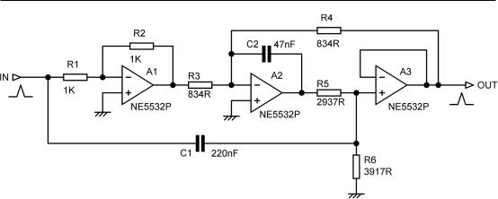
Figure 12.8: Bainter filter with symmetrical notch at 1 kHz and a Q of 2.3.
An Elliptical Filter Using a Bainter Highpass Notch
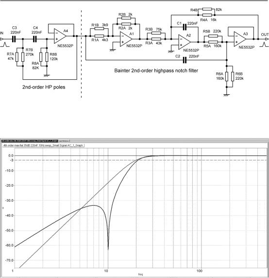
The ability of the Bainter to give either a lowpass or highpass notch makes it a very useful building block for elliptical filters that have a zero or zeros in the stopband. I have made use of this in designing a comprehensive suite of elliptical highpass subsonic filters to assist with vinyl reproduction. [3] What I consider the most effective of these is shown in Figure 12.9, with 2xE24 pairs given for the awkward resistor values. It is a 4th-order elliptical filter with a single stopband notch centred on 10
Hz, where spurious vinyl signals are often at their maximum level due to arm/cartridge resonance.
The complete filter consists of a 2nd-order highpass stageA4, placed at the front to reduce internal clipping problems (I call this the New Order) and followed by a Bainter highpass notch. The response is shown in Figure 12.10. The noise output was −113 dBu (22Hz–22kHz, rms sensing) with all opamps 5532. The filter easily handled 10 Vrms in/out at low distortion from 50 Hz to 50 kHz. My recent book Electronics for Vinyl [3] contains much more on subsonic filtering.
I like the Bainter filter. It is a very useful and well-behaved filter configuration. It may not be the simplest of filters, but its inherently deep notch and its good noise and distortion behaviour are a joy to work with. Mr Bainter, I salute you.
There are relatively few references to the Bainter filter in the literature; Valkenburg [4] is one.
The Bridged-Differentiator Notch Filter
Anotch filter that can be tuned with one control can be useful in development work. Figure 12.5d shows a bridged-differentiator notch filter tuneable from 80 to 180 Hz by RV1. R3 must theoretically be six times the total resistance betweenAand B, which here is 138 kΩ, but 139 kΩ gives a deeper notch, about −27 dB across the tuning range. The downside is that Q varies with frequency from 3.9 at 80 Hz to 1.4 at 180 Hz; clearly it is no substitute for a state-variable filter where frequency and Q can be changed independently. It may be an economical circuit in terms of amplifiers, but it uses three capacitors instead of the two in the 1-BPand Bainter filters.

Bandpass and Notch Filters 343
Figure 12.9: Schematic of practical 4th-order A0 = −35 dB classical highpass elliptical filter, using the New Order.
Figure 12.10: Frequency response of 4th-order A0 = −35 dB classic (non-MCP) highpass elliptical filter compared with 3rd-order Butterworth. Response is −3 dB at 21 Hz,
almost the same as the Butterworth, which is −3 dB at 20 Hz.
Boctor Notch Filters
Another interesting notch filter is the Boctor circuit, which uses only one opamp. [5], [6] Versions exist that can give either a lowpass or highpass notch. The design equations are complicated but can be found in the two references given. Figure 12.11 shows the lowpass and highpass versions.

344 Bandpass and Notch Filters
Figure 12.11: Lowpassnotch (a) and highpass notch (b) Boctor filters. The design at
(b) has a notch at 150 Hz with a Q of 1.
Figure 12.12: Response of Boctor filter in Figure 12.7b, giving a highpass notch at 150 Hz with a Q of 1.
Figure 12.12 shows the highpass notch produced by the Boctor circuit of Figure 12.11b; the highfrequency passband gain is +12 dB, with a gain of +6 dB on the low-frequency side of the notch. The capacitor values may be scaled to change the notch frequency, but they must be the same. A lowpass notch is the mirror image of this sort of response, with the low-gain section on the high-frequency side.
Like Bainter filters, Boctor highpass or lowpass notch filters are frequently used as a component part of elliptical filters.

Bandpass and Notch Filters 345
Other Notch Filters
The field of active filters is rich in possibilities. Other notch filters that there is no space to examine here, but which can be found in the filter textbooks, can be derived from biquad filters such as the Fliege filter, [7] the Tow-Thomas filter, the KHN state-variable filter, the Berka-Herpy filter, the Akerberg-Mossberg filter, and the Natarajan filter; these give symmetrical notches. See Chapter 10 for more on them. Filters apart from the Bainter and the Boctor that can generate highpass or lowpass notches are Friend’s SAB circuit [8] and the Scultety filter. The only reference I can find for the latter is [9], which at least gives the schematic; the same reference also gives schematics of the other filter mentioned in this section.
The Wien-Robinson filter is not biquad-based but uses a Wien network with feedback around it. [10] Notch depth depends on component accuracy, unlike the Bainter, and it seems to have no compensating advantages.
Simulating Notch Filters
When simulating notch filters, assessing the notch depth can be tricky.You need a lot of frequency steps to ensure you really have hit bottom with one of them. For example, in one run, 50 steps/decade showed a −20 dB notch, but upping it to 500 steps/decade revealed it was really −31 dB deep. In most cases having a stupendously deep notch is pointless. If you are trying to remove an unwanted signal, then it only has to alter in frequency by a tiny amount and you are on the side of the notch rather than the bottom, and the attenuation is much reduced. The exception to this is the THD analyser, where a very deep notch (120 dB or more) is needed to reject the fundamental so very low levels of harmonics can be measured. This is achieved by continuously servo-tuning the notch, so it is kept exactly on the incoming frequency.
References
[1]Augustadt, H. Electric Filter US Patent 2,106,785, February 1938, assigned to Bell Telephone Labs
[2]Bainter, J. R. “Active Filter Has Stable Notch, and Response Can Be Regulated” Electronics, pp. 115–117, 2 October 1975
[3]Self, Douglas “Electronics for Vinyl” Taylor & Francis, 2017
[4]Valkenburg, Van “Analog Filter Design”, pp. 346–349
[5]Boctor, S.A. “SingleAmplifier Functionally Tuneable Low-Pass Notch Filter” IEEE Trans Circuits & Systems, CAS-22, 1975, pp. 875–881
[6]Valkenburg, Van “Analog Filter Design”, p. 349
[7]Carter and Mancini (ed.) “Opamps for Everyone” Third Edn, Newnes, 2009, Chapter 21, p. 447, ISBN: 978- 1-85617-505-0
[8]Valkenburg, Van “Analog Filter Design”, p. 356
[9]www.schematica.com/active_filter_resources/a_list_of_active_filter_circuit_topologies.html;Accessed July 2017
[10]Tietze and Shenk “Electronic Circuits” Second Edn, Springer, 2008, pp. 825–826
