

280 Other Lowpass and Highpass Filters
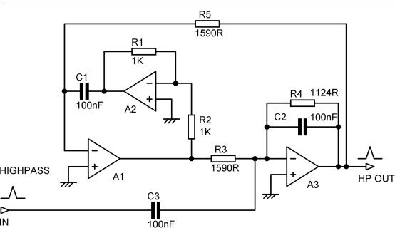
Figure 10.9: Akerberg-Mossberg 2nd-order highpass filter; cutoff 1 kHz. Not recommended.
There are also three capacitors instead of two, adding to the cost. However, errors in the value of C3 do not affect the cutoff frequency or Q of the filter, just the gain, moving the response up or down without changing its shape. Depending on the application, this may mean that the accuracy of C3 can be relaxed compared with C1 and C2.
Overall, the highpassAkerberg-Mossberg filter is interesting but not recommended. I have therefore not given the detailed design process.
Tow-Thomas Biquad Lowpass and Bandpass Filter
This lowpass and bandpass biquad filter configuration was introduced by Tow [4] and Thomas [5], [6] and is sometimes called the Ring-of-Three circuit. It should not be confused with the Ring-of- Two circuit, which is a clever way of making a voltage reference [7] and nothing to do with active filters. There are other multi-amplifier biquad configurations, but if the term “biquad” is used without qualification it normally means the Tow-Thomas biquad.All biquads are inherently 2nd-order, because the response is controlled by quadratic equations, but they can be cascaded into higher-order filters in the same way as other 2nd-order filters.
The Tow-Thomas biquad has advantages over other types of active filter. The component sensitivities are low. The distortion performance is good because all three amplifiers are working in shunt-feedback mode, so there is no common-mode signal on the opamp inputs and therefore no common-mode distortion. This is very much in contrast to the Sallen & Key filter, which usually has the full signal
Other Lowpass and Highpass Filters 281
voltage on the inputs. The TT biquad was built and measured (see Chapter 11) and proved very tractable and easy to apply. Unlike theAkerberg-Mossberg filter . . .
The Tow-Thomas biquad gives lowpass and bandpass responses simultaneously; this might allow for some elegant fill-driver crossovers (see Chapter 4) so long as the bandpass output has the correct Q. The bandpass output has −6 dB/octave skirts. The TT does not directly give a highpass output. Configurations that give all three responses directly are often called universal filters rather than
biquads; the KHN state-variable filter is the best-known example and is dealt with later in this chapter. The TT biquad is sometimes confused with the KHN state-variable filter because it has three amplifiers and apparently two integrators, but in the TT A1 is actually a leaky integrator, due to the presence of
R3, and not a pure integrator likeA2; the filter operation is quite different.
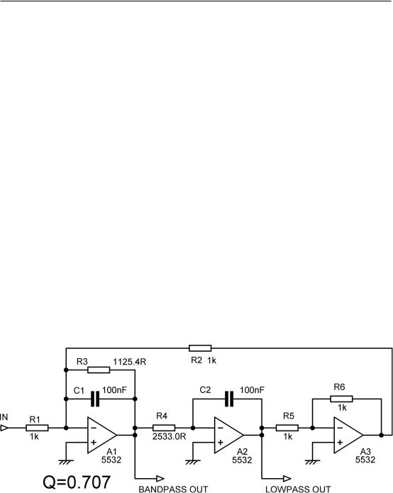
Figure 10.10 shows a Tow-Thomas 2nd-order Butterworth lowpass filter designed to give 0 dB gain in the passband of the lowpass output at A2. The lowpass output from A2 is in phase with the input in the passband. The output fromA3 is the same signal as atA2 but phase inverted, and it has to be said that having two lowpass outputs in anti-phase is rarely if ever useful in crossover design. The inverter is essential to the circuit operation, but as I have said elsewhere it irks me to have an opamp doing just a phase inversion; it hardly seems to be earning its keep.
The design process is: |
|
|
Decide the passband gain A required. |
|
|
Choose a convenient value for C |
C1 = C2 = C |
10.7 |
(It is not essential to have C1 = C2, but it is obviously convenient and simplifies the design.) Choose a convenient value for R2, such as 1 kΩ.
This however has deeper implications than mere convenience, which will be explained in a moment.
Figure 10.10: First version Tow-Thomas 2nd-order Butterworth lowpass biquad filter, centre frequency 1 kHz, +1 dB peak gain at A1 output.
282 Other Lowpass and Highpass Filters
Choose a convenient value for R5 = R6, such as 1 kΩ. |
|
10.8 |
|||||
Then: R3 = |
Q |
|
10.9 |
||||
2π f0C |
|
|
|
||||
1 |
|
|
|
10.10 |
|||
and: R4 = |
|
|
|
||||
(2π f0C)2 R2 |
|
||||||
Finally, R1 is set by the required passband gain A: R1 = |
R2 |
10.11 |
|||||
A |
|||||||
|
|
|
|
|
|
||
In any multi-amplifier filter, unity gain at one amplifier output can co-exist with more gain at the others, which will cause premature clipping internal to the filter. This needs to be checked for by simulation for each amplifier across the whole working frequency range. Here the output ofA3 is clearly at the same level asA2, so no problem there. But . . . simulation shows a peak gain of +1.0 dB at the A1 bandpass output, which is not exactly disastrous but not ideal for maximum headroom; we can do better. The gain in the lowpass passband is always unity so long as R1 = R2.
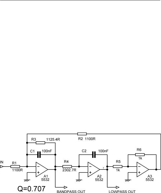
The initial choice of R2 = 1000 Ω gave us Figure 10.10. The gain atA1 output can be reduced by increasing the initial value of R2. So we try setting R2 = 1100 Ω and find that recalculating the values of R3 and R4 gives a peak gain atA1 output of only +0.2 dB, which we can ignore. R1 is now also set to R2 = 1100 Ω to maintain unity gain in the lowpass passband. R3 remains at the same value, since
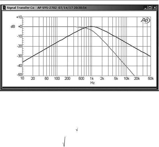
R2 does not appear in Equation 10.9, but R4 does change; see Figure 10.11. The frequency response of this circuit is shown in Figure 10.12. We will call it TTVersion 1; see Table 10.3.
Figure 10.11: Improved Tow-Thomas 2nd-order Butterworth lowpass biquad filter, centre frequency 1 kHz, +0.2 dB peak gain at A1 output. This is TT Version 1.
Other Lowpass and Highpass Filters 283
Figure 10.12: Tow-Thomas 2nd-order biquad filter; centre frequency 1 kHz.
The full analysis equations for the Tow-Thomas biquad, including non-equal capacitors, are:
Cutoff frequency: f0 |
= |
1 |
10.12 |
||
|
2π R2 R4 C1 C2 |
||||
For Q: Q = |
|
R32 C1 |
10.13 |
||
R2 R4 C2 |
|
||||
If C1 = C2 = C and R2 = R4 = R, which is also likely to be true in many cases, the analysis equations are much simplified:
Cutoff frequency: f0 = |
|
1 |
10.14 |
||||
2π RC |
|||||||
For Q: Q = |
R3 |
|
|
|
10.15 |
||
R |
|
|
|||||
|
|
|
|
|
|||
For passband gain A: A = |
|
R2 |
|
10.16 |
|||
|
R1 |
|
|||||
|
|
|
|
|
|
|
|
284 Other Lowpass and Highpass Filters
One of the advantages of the Tow-Thomas biquad over Sallen & Key configurations is that it allows what is called orthogonal tuning. This means that the three parameters of frequency f0, Q, and gain can be adjusted independently if it is done in the right order; thus:
1.Adjust R2 to get the required cutoff frequency f0.
2.Adjust R3 to get the required Q. This will not affect the f0 previously set.
3.Adjust R1 to get the desired passband gainA. This will not affect f0 or Q.
As R1 is feeding into a virtual earth point, this is pretty obvious, unlike Step 2.
This will not be useful for production purposes, as presumably all parameters have been decided and fixed by the use of fixed resistors. It can however be very handy during crossover development work.
If the filter Q is greater than 0.7071 (1/√2), then gain peaking will occur at the lowpass output around the cutoff frequency. If we assume a Q of 1 is required, as is used to make up a two-stage 3rd-order Butterworth filter, then the peaking is +1.25 dB, which has a small effect on the headroom. We will call this TTVersion 2, with the component values given in Table 10.3; they give 0 dB peak gain for the bandpass output, so there will be no headroom problems there. If you want to avoid any compromise on the headroom, the passband gain can be reduced as required by increasing the input resistor R1.
TTVersion 3 is a TT example with a Q of 2.56, the highest Q required in a four-stage Butterworth 8thorder filter. If we try R2 = 1000 Ω we get R3 = 4074.4 Ω and R4 = 2533.0 Ω. SPICE simulation then shows us that the gain peaks at +8.2 dB at the lowpass output, which is what we expect with a Q that is relatively high by crossover standards; the passband gain is still unity. However, as with all multi-stage filters, we must check the levels at every amplifier output. TheA3 output is an inverted version of A2 output, so there are no problems there. But . . . atA1 the bandpass output peaks at +12.1 dB at the cutoff frequency, and that is going to restrict headroom.
As we saw in the first example, the gain atA1 output can be reduced by increasing the initial value of
R2; this leads to a lower value for R4, so less gain is required in the A1 stage to give the same output at A2. R1 is then increased in the same ratio as R2 to keep the lowpass passband gain at unity. This process is illustrated in Table 10.2, which shows how increasing the initial value of R2 affects the other components and the gain distribution in the filter. Note that R3 does not change, as the Q is not changing.
Table 10.2: Component values for 1 kHz cutoff and Q = 2.56. R3 = 4074.4 Ω.
R5 = R6 and C1 = C2 = 100 nF.
R2 |
R4 |
R1 |
Peak gain at A1 out |
Peak gain at A2 out |
|
|
|
|
|
1000 Ω |
2533.0 Ω |
1000 Ω |
12.1 dB |
8.2 dB |
1590 Ω |
1593.1 Ω |
1590 Ω |
8.2 dB |
8.4 dB |
2000 Ω |
1266.5 Ω |
2000 Ω |
6.2 dB |
8.3 dB |
2500 Ω |
1013.2 Ω |
2500 Ω |
4.2 dB |
8.3 dB |
3000 Ω |
844.34 Ω |
3000 Ω |
2.6 dB |
8.3 dB |
4000 Ω |
633.26 Ω |
4000 Ω |
0.16 dB |
8.3 dB |
|
|
|
|
|