

92 Crossover Types
Figure 4.38: The frequency response of a 3rd-order 1.0 dB-Chebyshev crossover, resulting from summation with one of the filter outputs phase reversed. The dashed line is at −1 dB.
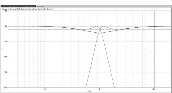
If one output is inverted we get instead a gentle dip, as in Figure 4.38, which looks more promising as a subject for frequency-offsetting.As we saw with the 3rd-order Linkwitz-Riley crossover, to tackle a dip in the combined response, it is necessary to push the curves together rather than pull them apart, and so the offset ratio will be less than 1.0.
An offset ratio of 0.946 (making the highpass cutoff 0.946 kHz and the lowpass cutoff 1/0.946 = 1.057 kHz, gives the maximally flat response in Figure 4.39. The response deviations are ±1.6 dB, and once more the Chebyshev filter does not look like a promising start for a crossover design.
Fourth-Order Crossovers
The 4th-order crossovers give still greater separation between the drive units than the 1st-, 2nd-, or 3rd-order types. The 24 dB/octave slopes minimise the chances that out-of-band drive unit
irregularities or tweeter and midrange resonances will be excited. Modulation distortion will be further reduced, though probably not to a great extent. The sensitivity to driver time-delay misalignments is further lessened due to the narrower crossover region. The 4th-order Butterworth crossover does not gives a flat summed amplitude response, but the 4th-order Linkwitz-Riley famously does. For the
Butterworth and Linkwitz-Riley versions, inverting one output gives a useless response with a deep notch at the crossover frequency.
Since 4th-order filters are used, their extra phase-shift gives outputs that are 360° apart, which is the same as being in-phase and so eliminates lobing errors and tilting of the vertical coverage pattern in the crossover region; this is a major advantage.

Crossover Types 93
Figure 4.39: Zooming in on the frequency response of a 3rd-order 1.0 dB-Chebyshev crossover, with frequency offset of 0.946 times and reversed-phase summation.
Ripple is ±1.6 dB, vertical scale ±2 dB.
Fourth-order crossovers have further reduced sensitivity to driver time-misalignments because of their steeper 24 dB/octave slopes. Vance Dickason records [2] that a 4th-order Butterworth crossover and a 2 inch time-misalignment gives an amplitude response error of about 1 dB, smaller than that of any other crossover examined so far.
Despite their advantages, 4th-order filters are rarely used in passive crossovers because the greater number of expensive inductors increases the losses due to their resistance, and increasing the inductor wire gauge to reduce these losses puts the cost up even more. Fourth-order crossovers also require a greater number of big capacitors.
I was inspired by Vance Dickason [2] to investigate some more exotic filters as possible candidates for crossovers; the linear-phase filter, the Gaussian filter, and the Legendre filter. It has to be said that on examination none look very promising. Other unusual filters such as transitional and synchronous types are looked at in Chapter 7.
Fourth-Order Butterworth Crossover
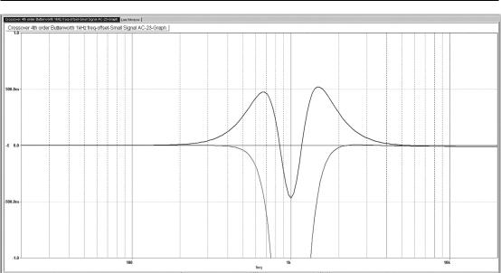
The 4th-order Butterworth sums to give a +3.0 dB hump at the crossover frequency, as in Figure 4.40, while the summation with one phase reversed gives a deep crevasse, as in Figure 4.41; this is the exact opposite of the behaviour of the 2nd-order Butterworth. A frequency offset of 1.128 times reduces the hump to a maximally flat ripple of ±0.47 dB, as seen in Figure 4.42.
Figure 4.40: The frequency response of a 4th-order Butterworth crossover, resulting from in-phase summation. The dashed line is at −3 dB.
Figure 4.41: The frequency response of a 4th-order Butterworth crossover with reverse-phase summation. The dashed line is at −3 dB.
Crossover Types 95
Figure 4.42: Zooming in on the frequency response of a 4th-order Butterworth crossover with in-phase summation, and an optimal frequency-offset
ratio of 1.128 times. The error is ±0.47 dB.
The 4th-order Butterworth crossover produces a flat power response, and so it is a CPC crossover. The outputs are 360° apart in phase at all times. This is equivalent to being in-phase, and so there is no tilting of the vertical coverage pattern in the crossover region. The summed group delay has a significant peak just below the crossover frequency.
Given that the best possible amplitude response flatness obtainable by frequency offset is ±0.47 dB, there seems no reason to use the 4th-order Butterworth in preference to the 4th-order Linkwitz-Riley crossover. The phase and group delay plots are therefore not shown.
Fourth-Order Linkwitz-Riley Crossover
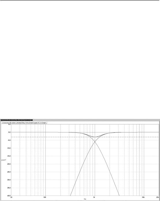
The 4th-order Linkwitz-Riley is considered by many the best crossover alignment of the lot. The inphase response sums to completely flat, making it anAPC type; see Figure 4.43. (The reversed-phase response in Figure 4.44 has a deep crevasse at the crossover frequency and is of no value.) The outputs are 360° apart in phase at all times, so there is no lobe tilting in the crossover region. The crossover point is at −6 dB. There is a −3 dB dip in the power response, so it is not a CPC crossover.
One of the beauties of this type of crossover is the ease of its design. It is normally made by cascading two 2nd-order Butterworth filters with identical cutoff frequencies and identical Q’s of 0.7071 (1/√2). Thus it is sometimes called a “squared Butterworth” filter, or, less logically, a “−6 dB Butterworth” filter.
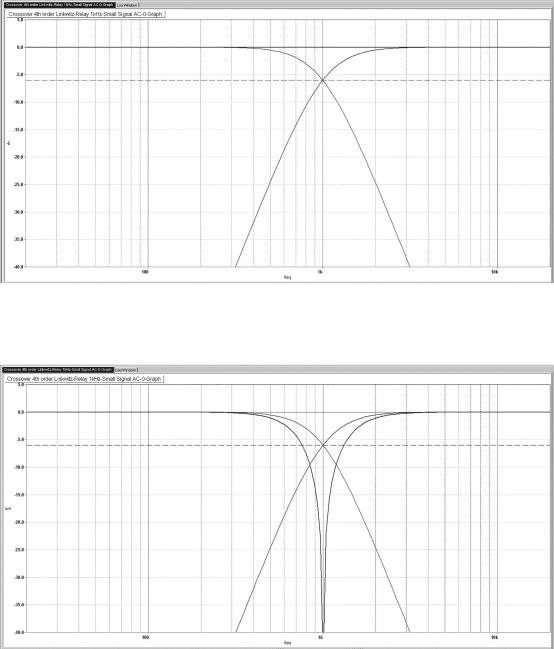
Figure 4.43: The frequency response of a 4th-order Linkwitz-Riley crossover, resulting from in-phase summation. The dashed line is at −6 dB.
Figure 4.44: The frequency response of a 4th-order Linkwitz-Riley crossover, resulting from phase-inverted summation. The dashed line is at −6 dB.
Crossover Types 97
Figure 4.45 shows the −3 dB dip in the power response. The two outputs are at −6 dB at the crossover point and are regarded as uncorrelated, so they RMS-sum to give −3 dB. While this is not ideal, it is a modest dip, and the use of 4th-order filters means it is not wide, so the effect on the reverberant energy in a listening space will be correspondingly small.
Figure 4.46 illustrates how the outputs are 360° apart in phase at all times. This is equivalent to being in-phase and so eliminates tilting of the vertical coverage lobes in the crossover region. The summed phase swings through 360° across the audio band and thus emulates a 2nd-order allpass filter.
The summed group delay in Figure 4.47 has a flat LF region at 450 usec, which is longer than any of the lower-order crossovers we have looked at; however, that is much less than the 3.2 ms audibility threshold at 500 Hz, as quoted in Chapter 3. The group delay shows a moderate peak of 540 usec just below the crossover frequency.
Passive versions of the 4th-order Linkwitz-Riley are relatively uncommon because of the power losses and the number of components in a passive 4th-order crossover, but one example of a loudspeaker using the technology was the KEF Model 105, [5] of which the first version was released in 1977.
The 4th-order Linkwitz-Riley crossover is widely considered to be the best. It sums to a flat amplitude response, and its power response has a dip of limited width which is only −3 dB deep. There is no lobe tilting, and the 24 dB/octave slopes are considered adequate for the vast majority of drive units. On the debit side, the phase response is that of a 2nd-order allpass filter rather than a 1st-order, and the group delay is relatively long, at 450 usec, and has a peak.
Figure 4.45: The power response of a 4th-order Linkwitz-Riley crossover, resulting from in-phase summation. The dashed line is at −3 dB.
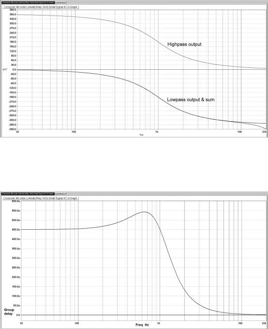
Figure 4.46: The phase response of a 4th-order Linkwitz-Riley crossover, in-phase connection. There is a constant 360° phase difference between the two outputs (the summed phase trace is on top of the lowpass output trace).
Figure 4.47: The group delay response of a 4th-order Linkwitz-Riley crossover, in-phase connection.