

- •Contents
- •Acknowledgments
- •Preface
- •What a Crossover Does
- •Why a Crossover Is Necessary
- •Beaming and Lobing
- •Passive Crossovers
- •Active Crossover Applications
- •Bi-Amping and Bi-Wiring
- •Loudspeaker Cables
- •The Advantages and Disadvantages of Active Crossovers
- •The Advantages of Active Crossovers
- •Some Illusory Advantages of Active Crossovers
- •The Disadvantages of Active Crossovers
- •The Next Step in Hi-Fi
- •Active Crossover Systems
- •Matching Crossovers and Loudspeakers
- •A Modest Proposal: Popularising Active Crossovers
- •Multi-Way Connectors
- •Subjectivism
- •Sealed-Box Loudspeakers
- •Reflex (Ported) Loudspeakers
- •Auxiliary Bass Radiator (ABR) Loudspeakers
- •Transmission Line Loudspeakers
- •Horn Loudspeakers
- •Electrostatic Loudspeakers
- •Ribbon Loudspeakers
- •Electromagnetic Planar Loudspeakers
- •Air-Motion Transformers
- •Plasma Arc Loudspeakers
- •The Rotary Woofer
- •MTM Tweeter-Mid Configurations (d’Appolito)
- •Vertical Line Arrays
- •Line Array Amplitude Tapering
- •Line Array Frequency Tapering
- •CBT Line Arrays
- •Diffraction
- •Sound Absorption in Air
- •Modulation Distortion
- •Drive Unit Distortion
- •Doppler Distortion
- •Further Reading on Loudspeaker Design
- •General Crossover Requirements
- •1 Adequate Flatness of Summed Amplitude/Frequency Response On-Axis
- •2 Sufficiently Steep Roll-Off Slopes Between the Filter Outputs
- •3 Acceptable Polar Response
- •4 Acceptable Phase Response
- •5 Acceptable Group Delay Behaviour
- •Further Requirements for Active Crossovers
- •1 Negligible Extra Noise
- •2 Negligible Impairment of System Headroom
- •3 Negligible Extra Distortion
- •4 Negligible Impairment of Frequency Response
- •5 Negligible Impairment of Reliability
- •Linear Phase
- •Minimum Phase
- •Absolute Phase
- •Phase Perception
- •Target Functions
- •All-Pole and Non-All-Pole Crossovers
- •Symmetric and Asymmetric Crossovers
- •Allpass and Constant-Power Crossovers
- •Constant-Voltage Crossovers
- •First-Order Crossovers
- •First-Order Solen Split Crossover
- •First-Order Crossovers: 3-Way
- •Second-Order Crossovers
- •Second-Order Butterworth Crossover
- •Second-Order Linkwitz-Riley Crossover
- •Second-Order Bessel Crossover
- •Second-Order 1.0 dB-Chebyshev Crossover
- •Third-Order Crossovers
- •Third-Order Butterworth Crossover
- •Third-Order Linkwitz-Riley Crossover
- •Third-Order Bessel Crossover
- •Third-Order 1.0 dB-Chebyshev Crossover
- •Fourth-Order Crossovers
- •Fourth-Order Butterworth Crossover
- •Fourth-Order Linkwitz-Riley Crossover
- •Fourth-Order Bessel Crossover
- •Fourth-Order 1.0 dB-Chebyshev Crossover
- •Fourth-Order Linear-Phase Crossover
- •Fourth-Order Gaussian Crossover
- •Fourth-Order Legendre Crossover
- •Higher-Order Crossovers
- •Determining Frequency Offsets
- •Filler-Driver Crossovers
- •The Duelund Crossover
- •Crossover Topology
- •Crossover Conclusions
- •Elliptical Filter Crossovers
- •Neville Thiele MethodTM (NTM) Crossovers
- •Subtractive Crossovers
- •First-Order Subtractive Crossovers
- •Second-Order Butterworth Subtractive Crossovers
- •Third-Order Butterworth Subtractive Crossovers
- •Fourth-Order Butterworth Subtractive Crossovers
- •Subtractive Crossovers With Time Delays
- •Performing the Subtraction
- •Active Filters
- •Lowpass Filters
- •Highpass Filters
- •Bandpass Filters
- •Notch Filters
- •Allpass Filters
- •All-Stop Filters
- •Brickwall Filters
- •The Order of a Filter
- •Filter Cutoff Frequencies and Characteristic Frequencies
- •First-Order Filters
- •Second-Order and Higher-Order Filters
- •Filter Characteristics
- •Amplitude Peaking and Q
- •Butterworth Filters
- •Linkwitz-Riley Filters
- •Bessel Filters
- •Chebyshev Filters
- •1 dB-Chebyshev Lowpass Filter
- •3 dB-Chebyshev Lowpass Filter
- •Higher-Order Filters
- •Butterworth Filters up to 8th-Order
- •Linkwitz-Riley Filters up to 8th-Order
- •Bessel Filters up to 8th-Order
- •Chebyshev Filters up to 8th-Order
- •More Complex Filters—Adding Zeros
- •Inverse Chebyshev Filters (Chebyshev Type II)
- •Elliptical Filters (Cauer Filters)
- •Some Lesser-Known Filter Characteristics
- •Transitional Filters
- •Linear-Phase Filters
- •Gaussian Filters
- •Legendre-Papoulis Filters
- •Laguerre Filters
- •Synchronous Filters
- •Other Filter Characteristics
- •Designing Real Filters
- •Component Sensitivity
- •First-Order Lowpass Filters
- •Second-Order Filters
- •Sallen & Key 2nd-Order Lowpass Filters
- •Sallen & Key Lowpass Filter Components
- •Sallen & Key 2nd-Order Lowpass: Unity Gain
- •Sallen & Key 2nd-Order Lowpass Unity Gain: Component Sensitivity
- •Filter Frequency Scaling
- •Sallen & Key 2nd-Order Lowpass: Equal Capacitor
- •Sallen & Key 2nd-Order Lowpass Equal-C: Component Sensitivity
- •Sallen & Key 2nd-Order Butterworth Lowpass: Defined Gains
- •Sallen & Key 2nd-Order Lowpass: Non-Equal Resistors
- •Sallen & Key 2nd-Order Lowpass: Optimisation
- •Sallen & Key 3rd-Order Lowpass: Two Stages
- •Sallen & Key 3rd-Order Lowpass: Single Stage
- •Sallen & Key 4th-Order Lowpass: Two Stages
- •Sallen & Key 4th-Order Lowpass: Single-Stage Butterworth
- •Sallen & Key 4th-Order Lowpass: Single-Stage Linkwitz-Riley
- •Sallen & Key 5th-Order Lowpass: Three Stages
- •Sallen & Key 5th-Order Lowpass: Two Stages
- •Sallen & Key 5th-Order Lowpass: Single Stage
- •Sallen & Key 6th-Order Lowpass: Three Stages
- •Sallen & Key 6th-Order Lowpass: Single Stage
- •Sallen & Key Lowpass: Input Impedance
- •Linkwitz-Riley Lowpass With Sallen & Key Filters: Loading Effects
- •Lowpass Filters With Attenuation
- •Bandwidth Definition Filters
- •Bandwidth Definition: Butterworth Versus Bessel
- •Variable-Frequency Lowpass Filters: Sallen & Key
- •First-Order Highpass Filters
- •Sallen & Key 2nd-Order Filters
- •Sallen & Key 2nd-Order Highpass Filters
- •Sallen & Key Highpass Filter Components
- •Sallen & Key 2nd-Order Highpass: Unity Gain
- •Sallen & Key 2nd-Order Highpass: Equal Resistors
- •Sallen & Key 2nd-Order Butterworth Highpass: Defined Gains
- •Sallen & Key 2nd-Order Highpass: Non-Equal Capacitors
- •Sallen & Key 3rd-Order Highpass: Two Stages
- •Sallen & Key 3rd-Order Highpass in a Single Stage
- •Sallen & Key 4th-Order Highpass: Two Stages
- •Sallen & Key 4th-Order Highpass: Butterworth in a Single Stage
- •Sallen & Key 4th-Order Highpass: Linkwitz-Riley in a Single Stage
- •Sallen & Key 4th-Order Highpass: Single-Stage With Other Filter Characteristics
- •Sallen & Key 5th-Order Highpass: Three Stages
- •Sallen & Key 5th-Order Butterworth Filter: Two Stages
- •Sallen & Key 5th-Order Highpass: Single Stage
- •Sallen & Key 6th-Order Highpass: Three Stages
- •Sallen & Key 6th-Order Highpass: Single Stage
- •Sallen & Key Highpass: Input Impedance
- •Bandwidth Definition Filters
- •Bandwidth Definition: Subsonic Filters
- •Bandwidth Definition: Combined Ultrasonic and Subsonic Filters
- •Variable-Frequency Highpass Filters: Sallen & Key
- •Designing Filters
- •Multiple-Feedback Filters
- •Multiple-Feedback 2nd-Order Lowpass Filters
- •Multiple-Feedback 2nd-Order Highpass Filters
- •Multiple-Feedback 3rd-Order Filters
- •Multiple-Feedback 3rd-Order Lowpass Filters
- •Multiple-Feedback 3rd-Order Highpass Filters
- •Biquad Filters
- •Akerberg-Mossberg Lowpass Filter
- •Akerberg-Mossberg Highpass Filters
- •Tow-Thomas Biquad Lowpass and Bandpass Filter
- •Tow-Thomas Biquad Notch and Allpass Responses
- •Tow-Thomas Biquad Highpass Filter
- •State-Variable Filters
- •Variable-Frequency Filters: State-Variable 2nd Order
- •Variable-Frequency Filters: State-Variable 4th-Order
- •Variable-Frequency Filters: Other Orders of State-Variable
- •Other Filters
- •Aspects of Filter Performance: Noise and Distortion
- •Distortion in Active Filters
- •Distortion in Sallen & Key Filters: Looking for DAF
- •Distortion in Sallen & Key Filters: 2nd-Order Lowpass
- •Distortion in Sallen & Key Filters: 2nd-Order Highpass
- •Mixed Capacitors in Low-Distortion 2nd-Order Sallen & Key Filters
- •Distortion in Sallen & Key Filters: 3rd-Order Lowpass Single Stage
- •Distortion in Sallen & Key Filters: 3rd-Order Highpass Single Stage
- •Distortion in Sallen & Key Filters: 4th-Order Lowpass Single Stage
- •Distortion in Sallen & Key Filters: 4th-Order Highpass Single Stage
- •Distortion in Sallen & Key Filters: Simulations
- •Distortion in Sallen & Key Filters: Capacitor Conclusions
- •Distortion in Multiple-Feedback Filters: 2nd-Order Lowpass
- •Distortion in Multiple-Feedback Filters: 2nd-Order Highpass
- •Distortion in Tow-Thomas Filters: 2nd-Order Lowpass
- •Distortion in Tow-Thomas Filters: 2nd-Order Highpass
- •Noise in Active Filters
- •Noise and Bandwidth
- •Noise in Sallen & Key Filters: 2nd-Order Lowpass
- •Noise in Sallen & Key Filters: 2nd-Order Highpass
- •Noise in Sallen & Key Filters: 3rd-Order Lowpass Single Stage
- •Noise in Sallen & Key Filters: 3rd-Order Highpass Single Stage
- •Noise in Sallen & Key Filters: 4th-Order Lowpass Single Stage
- •Noise in Sallen & Key Filters: 4th-Order Highpass Single Stage
- •Noise in Multiple-Feedback Filters: 2nd-Order Lowpass
- •Noise in Multiple-Feedback Filters: 2nd-Order Highpass
- •Noise in Tow-Thomas Filters
- •Multiple-Feedback Bandpass Filters
- •High-Q Bandpass Filters
- •Notch Filters
- •The Twin-T Notch Filter
- •The 1-Bandpass Notch Filter
- •The Bainter Notch Filter
- •Bainter Notch Filter Design
- •Bainter Notch Filter Example
- •An Elliptical Filter Using a Bainter Highpass Notch
- •The Bridged-Differentiator Notch Filter
- •Boctor Notch Filters
- •Other Notch Filters
- •Simulating Notch Filters
- •The Requirement for Delay Compensation
- •Calculating the Required Delays
- •Signal Summation
- •Physical Methods of Delay Compensation
- •Delay Filter Technology
- •Sample Crossover and Delay Filter Specification
- •Allpass Filters in General
- •First-Order Allpass Filters
- •Distortion and Noise in 1st-Order Allpass Filters
- •Cascaded 1st-Order Allpass Filters
- •Second-Order Allpass Filters
- •Distortion and Noise in 2nd-Order Allpass Filters
- •Third-Order Allpass Filters
- •Distortion and Noise in 3rd-Order Allpass Filters
- •Higher-Order Allpass Filters
- •Delay Lines for Subtractive Crossovers
- •Variable Allpass Time Delays
- •Lowpass Filters for Time Delays
- •The Need for Equalisation
- •What Equalisation Can and Can’t Do
- •Loudspeaker Equalisation
- •1 Drive Unit Equalisation
- •3 Bass Response Extension
- •4 Diffraction Compensation Equalisation
- •5 Room Interaction Correction
- •Equalisation Circuits
- •HF-Cut and LF-Boost Equaliser
- •Combined HF-Boost and HF-Cut Equaliser
- •Adjustable Peak/Dip Equalisers: Fixed Frequency and Low Q
- •Adjustable Peak/Dip Equalisers With High Q
- •Parametric Equalisers
- •The Bridged-T Equaliser
- •The Biquad Equaliser
- •Capacitance Multiplication for the Biquad Equaliser
- •Equalisers With Non-Standard Slopes
- •Equalisers With −3 dB/Octave Slopes
- •Equalisers With −3 dB/Octave Slopes Over Limited Range
- •Equalisers With −4.5 dB/Octave Slopes
- •Equalisers With Other Slopes
- •Equalisation by Filter Frequency Offset
- •Equalisation by Adjusting All Filter Parameters
- •Component Values
- •Resistors
- •Through-Hole Resistors
- •Surface-Mount Resistors
- •Resistors: Values and Tolerances
- •Resistor Value Distributions
- •Obtaining Arbitrary Resistance Values
- •Other Resistor Combinations
- •Resistor Noise: Johnson and Excess Noise
- •Resistor Non-Linearity
- •Capacitors: Values and Tolerances
- •Obtaining Arbitrary Capacitance Values
- •Capacitor Shortcomings
- •Non-Electrolytic Capacitor Non-Linearity
- •Electrolytic Capacitor Non-Linearity
- •Active Devices for Active Crossovers
- •Opamp Types
- •Opamp Properties: Noise
- •Opamp Properties: Slew Rate
- •Opamp Properties: Common-Mode Range
- •Opamp Properties: Input Offset Voltage
- •Opamp Properties: Bias Current
- •Opamp Properties: Cost
- •Opamp Properties: Internal Distortion
- •Opamp Properties: Slew Rate Limiting Distortion
- •Opamp Properties: Distortion Due to Loading
- •Opamp Properties: Common-Mode Distortion
- •Opamps Surveyed
- •The TL072 Opamp
- •The NE5532 and 5534 Opamps
- •The 5532 With Shunt Feedback
- •5532 Output Loading in Shunt-Feedback Mode
- •The 5532 With Series Feedback
- •Common-Mode Distortion in the 5532
- •Reducing 5532 Distortion by Output Stage Biasing
- •Which 5532?
- •The 5534 Opamp
- •The LM4562 Opamp
- •Common-Mode Distortion in the LM4562
- •The LME49990 Opamp
- •Common-Mode Distortion in the LME49990
- •The AD797 Opamp
- •Common-Mode Distortion in the AD797
- •The OP27 Opamp
- •Opamp Selection
- •Crossover Features
- •Input Level Controls
- •Subsonic Filters
- •Ultrasonic Filters
- •Output Level Trims
- •Output Mute Switches, Output Phase-Reverse Switches
- •Control Protection
- •Features Usually Absent
- •Metering
- •Relay Output Muting
- •Switchable Crossover Modes
- •Noise, Headroom, and Internal Levels
- •Circuit Noise and Low-Impedance Design
- •Using Raised Internal Levels
- •Placing the Output Attenuator
- •Gain Structures
- •Noise Gain
- •Active Gain Controls
- •Filter Order in the Signal Path
- •Output Level Controls
- •Mute Switches
- •Phase-Invert Switches
- •Distributed Peak Detection
- •Power Amplifier Considerations
- •Subwoofer Applications
- •Subwoofer Technologies
- •Sealed-Box (Infinite Baffle) Subwoofers
- •Reflex (Ported) Subwoofers
- •Auxiliary Bass Radiator (ABR) Subwoofers
- •Transmission Line Subwoofers
- •Bandpass Subwoofers
- •Isobaric Subwoofers
- •Dipole Subwoofers
- •Horn-Loaded Subwoofers
- •Subwoofer Drive Units
- •Hi-Fi Subwoofers
- •Home Entertainment Subwoofers
- •Low-Level Inputs (Unbalanced)
- •Low-Level Inputs (Balanced)
- •High-Level Inputs
- •High-Level Outputs
- •Mono Summing
- •LFE Input
- •Level Control
- •Crossover In/Out Switch
- •Crossover Frequency Control (Lowpass Filter)
- •Highpass Subsonic Filter
- •Phase Switch (Normal/Inverted)
- •Variable Phase Control
- •Signal Activation Out of Standby
- •Home Entertainment Crossovers
- •Fixed Frequency
- •Variable Frequency
- •Multiple Variable
- •Power Amplifiers for Home Entertainment Subwoofers
- •Subwoofer Integration
- •Sound-Reinforcement Subwoofers
- •Line or Area Arrays
- •Cardioid Subwoofer Arrays
- •Aux-Fed Subwoofers
- •Automotive Audio Subwoofers
- •Motional Feedback Loudspeakers
- •History
- •Feedback of Position
- •Feedback of Velocity
- •Feedback of Acceleration
- •Other MFB Speakers
- •Published Projects
- •Conclusions
- •External Signal Levels
- •Internal Signal Levels
- •Input Amplifier Functions
- •Unbalanced Inputs
- •Balanced Interconnections
- •The Advantages of Balanced Interconnections
- •The Disadvantages of Balanced Interconnections
- •Balanced Cables and Interference
- •Balanced Connectors
- •Balanced Signal Levels
- •Electronic vs Transformer Balanced Inputs
- •Common-Mode Rejection Ratio (CMRR)
- •The Basic Electronic Balanced Input
- •Common-Mode Rejection Ratio: Opamp Gain
- •Common-Mode Rejection Ratio: Opamp Frequency Response
- •Common-Mode Rejection Ratio: Opamp CMRR
- •Common-Mode Rejection Ratio: Amplifier Component Mismatches
- •A Practical Balanced Input
- •Variations on the Balanced Input Stage
- •Combined Unbalanced and Balanced Inputs
- •The Superbal Input
- •Switched-Gain Balanced Inputs
- •Variable-Gain Balanced Inputs
- •The Self Variable-Gain Balanced Input
- •High Input Impedance Balanced Inputs
- •The Instrumentation Amplifier
- •Instrumentation Amplifier Applications
- •The Instrumentation Amplifier With 4x Gain
- •The Instrumentation Amplifier at Unity Gain
- •Transformer Balanced Inputs
- •Input Overvoltage Protection
- •Noise and Balanced Inputs
- •Low-Noise Balanced Inputs
- •Low-Noise Balanced Inputs in Real Life
- •Ultra-Low-Noise Balanced Inputs
- •Unbalanced Outputs
- •Zero-Impedance Outputs
- •Ground-Cancelling Outputs
- •Balanced Outputs
- •Transformer Balanced Outputs
- •Output Transformer Frequency Response
- •Transformer Distortion
- •Reducing Transformer Distortion
- •Opamp Supply Rail Voltages
- •Designing a ±15 V Supply
- •Designing a ±17 V Supply
- •Using Variable-Voltage Regulators
- •Improving Ripple Performance
- •Dual Supplies From a Single Winding
- •Mutual Shutdown Circuitry
- •Power Supplies for Discrete Circuitry
- •Design Principles
- •Example Crossover Specification
- •The Gain Structure
- •Resistor Selection
- •Capacitor Selection
- •The Balanced Line Input Stage
- •The Bandwidth Definition Filter
- •The HF Path: 3 kHz Linkwitz-Riley Highpass Filter
- •The HF Path: Time-Delay Compensation
- •The MID Path: Topology
- •The MID Path: 400 Hz Linkwitz-Riley Highpass Filter
- •The MID Path: 3 kHz Linkwitz-Riley Lowpass Filter
- •The MID Path: Time-Delay Compensation
- •The LF Path: 400 Hz Linkwitz-Riley Lowpass Filter
- •The LF Path: No Time-Delay Compensation
- •Output Attenuators and Level Trim Controls
- •Balanced Outputs
- •Crossover Programming
- •Noise Analysis: Input Circuitry
- •Noise Analysis: HF Path
- •Noise Analysis: MID Path
- •Noise Analysis: LF Path
- •Improving the Noise Performance: The MID Path
- •Improving the Noise Performance: The Input Circuitry
- •The Noise Performance: Comparisons With Power Amplifier Noise
- •Conclusion
- •Index
Opamps for Active Crossovers 485
The LM4562 Opamp
The LM4562 is a relatively new opamp which first become freely available at the beginning of 2007. It is a National Semiconductor product. It is a dual opamp—there is no single or quad version. It costs about ten times as much as a 5532.
The input noise voltage is typically 2.7 nV/√Hz, which is substantially lower than the 5 nV/√Hz of the 5532. For suitable applications with low source impedances this translates into a useful noise advantage of 5.3 dB. The bias current is 10 nAtypical, which is very low and would normally imply that bias cancellation, with its attendant noise problems, was being used. However, in my testing
I have seen no sign of excess noise, and the data sheet is silent on the subject. No details of the internal circuitry have been released so far, and quite probably never will be. The LM4562 is not fussy about decoupling, and as with the 5532, 100 nF across the supply rails close to the package seems to ensure HF stability. The slew rate is typically ±20 V/us, more than twice as fast as the 5532.
The first THD plot in Figure 16.16 shows the LM4562 working at a closed-loop gain of 2.2 times in shunt-feedback mode, at a high level of 10 Vrms. The top of the THD scale is now a very low 0.001%, and the plots look a bit jagged because of noise. The no-load trace is barely distinguishable from the APSYS-2702 output, and even with a heavy 500 Ω load driven at 10 Vrms there is only a very small
Figure 16.16: The LM4562 in shunt-feedback mode, with 1 kΩ, 2k2 feedback resistors giving a gain of 2.2x. Shown for no load (NL) and 1 kΩ, 500 Ω loads. Note the vertical scale ends at
0.001% this time. Output level is 10 Vrms. ±18 V supply rails.

486 Opamps for Active Crossovers
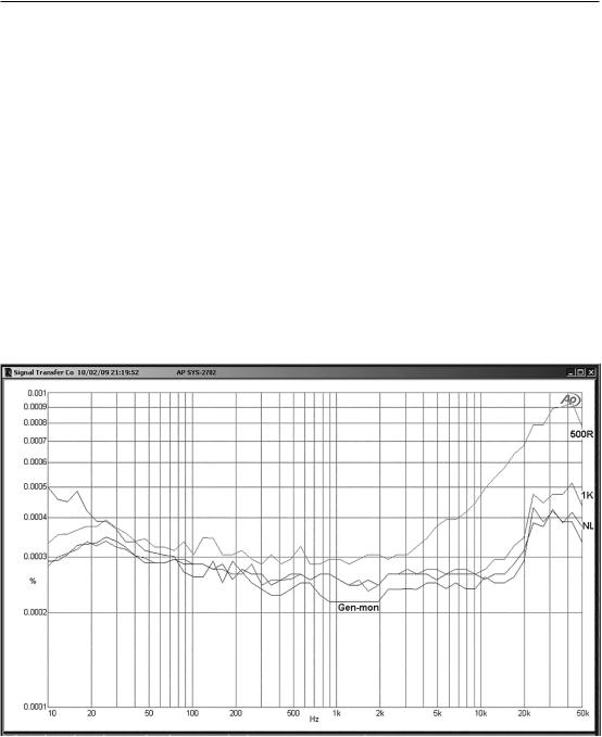
Figure 16.17: The LM4562 in series-feedback mode, with 1 kΩ, 2k2 feedback resistors giving a gain of 3.2x. No load (NL) and 500 Ω load. 10 Vrms output. ±18 V supply rails.
amount of extra THD, reaching 0.0007% at 20 kHz. Compare this with the 5532 performance in Figure 16.7, where loading brings up the distortion in the flat region below 10 kHz to 0.0008% and gives a THD of 0.0020% at 20 kHz with a 500 Ω load, as opposed to only 0.0007% for the LM4562.
Figure 16.17 shows the LM4562 working at a gain of 3.2x in series-feedback mode, both modes having a noise gain of 3.2 times. The extra distortion from the 500 Ω loading is very low.
Common-Mode Distortion in the LM4562
For Figures 16.16 and 16.17 the feedback resistances were 2k2 and 1 kΩ, so the minimum source resistance presented to the inverting input is 688 Ω. In Figure 16.18 extra source resistances were then put in series with the input path (as was done with the 5532 in the section on common-mode distortion), and this revealed a remarkable property of the LM4562—with moderate levels of CM voltage it is much more resistant to common-mode distortion than the 5532.At 10 Vrms and 10 kHz, with a 10 kΩ source resistance, the 5532 generates 0.0014% THD (see Figure 16.9), but the LM4562 gives only 0.00046% under the same conditions. I strongly suspect that the LM4562 has a more sophisticated input stage than the 5532, probably incorporating cascoding to minimise the effects of common-mode voltages. Note that only the rising curves to the right represent actual distortion. The

Opamps for Active Crossovers 487
Figure 16.18: The LM4562 in series-feedback mode, gain 3.2x, with varying extra source resistance in the input path. The extra distortion is much lower than for the 5532.
10 Vrms out, ±18 V supply rails.
raised levels of the horizontal traces at the LF end are due to Johnson noise from the added series resistances, plus opamp current noise flowing in them.
As we saw with the 5532, the voltage-follower configuration is the most demanding test for CM distortion, because the CM voltage is at a maximum. Now the LM4562 does not work quite so well. At 10 kHz the distortion with a 10 kΩ source resistance has leapt up from 0.00046% in Figure 16.18 to 0.0037% in Figure 16.19, which allowing for the noise component in the former must be an increase of some ten times. This is a surprising and unwelcome result, because it means that despite its much greater cost the performance of the LM4562 in this configuration is no better than that of the 5532; compare Figure 16.10.
The reason for this rapid increase in distortion with CM voltage appear to be a non-linearity mechanism that is activated quite suddenly when the CM voltage exceeds 4 Vrms. This is illustrated in Figure 16.20, which shows distortion against level for the voltage-follower at 10 kHz, with different source resistances. The left side of the plot shows only noise decreasing relatively as the test level increases; the steps in the lowest trace are measurement artefacts. Since the CM voltage for the seriesfeedback configuration is only about 3 Vrms, the non-linearity mechanism is not activated, and CM distortion in that case is very low.

488 Opamps for Active Crossovers
Figure 16.19: The LM4562 in voltage-follower mode, with varying extra source resistance in the input path. CM distortion is much higher than for the series-feedback amplifier in Figure 16.16.
10 Vrms out, ±18 V supply rails.
The conclusion has to be once more that if you are using voltage-followers and want low distortion, it is well worthwhile to expend some time and trouble on getting the source impedances as low as possible.
It has taken an unbelievably long time—nearly 30 years—for a better audio opamp than the 5532 to come along, but at last it has happened. The LM4562 is superior in just about every parameter, apart from having more than twice as much current noise and no better CM distortion in voltagefollower use. These issues should not be serious problems if the low-impedance design philosophy is followed.At present the LM4562 has a much higher price; hopefully that will change, but it may take a very long time, based on the price history of other opamps. It has already begun to appear in hi-fi equipment, one example being the Benchmark DAC1 HDR, a combined DAC and preamplifier.
There is, however, or at any rate appears to be, a slight problem with using the LM4562 as a voltagefollower. On several occasions I have built such a voltage-follower, supplied it with a low source impedance such as 40 Ω, and attempted to measure the noise performance. This has been rendered impossible by the stage picking up and demodulating radio stations. In the same circuit position a 5532 works fine. I assume some internal oscillation is causing heterodyning; no oscillation is visible on the output.Acure I found helpful is connecting the inverting input to the opamp output with a 100 Ω