

10.3 The Modulation Mode of Method of Crack Location |
97 |
Let uω represent the displacement in the rod caused by the high frequency wave propagating in t. The low frequency and the high frequency waves do not interact with each other if there is no crack in the rod. Interaction takes place if there is a crack in the sample. A modulation effect will be produced which is proportional to the product of un (z, t) and uω , subjected to the approximation of quadratic nonlinearity:
|
(10.2) |
un = α.un (z0)uω |
where u = amplitude of the wave generated by the nonlinear force in the crack at
n
the combination frequency components (modulation frequency components) ω ±n . If one assumes that the newly generated high frequency waves at the combination frequencies propagate in the medium as in an infinite one D medium, then the modulation index is defined as
|
1 |
|
|
1 |
|
|
|
|
|
|
|
Mn= An /un |uω / = |
An /[α.un (z0)uω /uω ]/ = α[/un (z0)/]/ An |
(10.3) |
|||||||||
Then the parameter is introduced as |
|
|
|
||||||||
|
|
|
|
|
|
α/un (z0)/ |
|
|
|||
M (z, z0) = |
/Mn sin k z/ = |
|
/ |
sin k z = α / sin k z0. sin k z/ |
|||||||
|
|
|
|||||||||
n |
|
An |
|||||||||
|
n |
|
|
|
|
|
|
n |
|
||
|
|
|
|
|
|
|
|
|
|
|
(10.4) |
where k = π n/l.
Equation (10.4) shows that the parameter M has a peak value at the position of the crack, at z = z0. A second peak takes place at z = l − z0. The spatial resolution of the modulation method depends on the number of excited modes of the flexural oscillation.
10.4Experimental Procedure of the Modulation Method for NDT
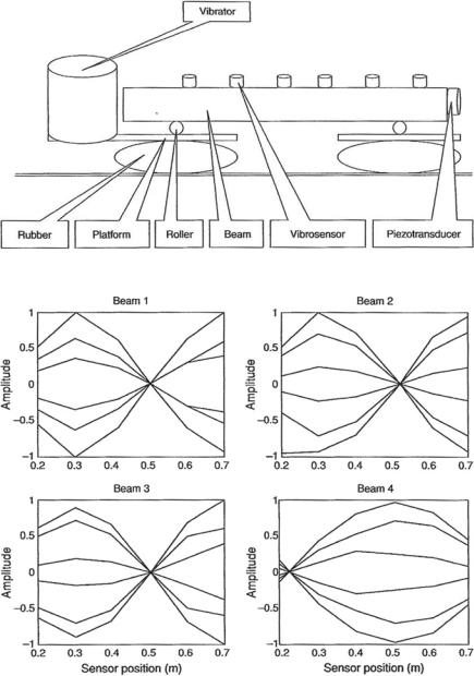
An example of the application of the modulation acoustic method is to nondestructive testing such as the diagnostics of concrete beams. Figure 10.1 shows a scheme of the experiments with concrete neam. Here four concrete beams were used. These four beams have conditions as follows: Beam 1 with a spherical flaw of 3 cm diameter; beam 2 with a transverse artificially made crack; beam 3 with no defects and is used as a reference; beam 4 has an inner reinforcement. The modulation of high frequency 16 kHz acoustic waves generated with a piezoelectric transducer by a low frequency flexural beam vibration excited with the vibrator at the resonance frequencies of the first and the second modes of beam. was studied [1]. Figure 10.2 shows the corresponding diagram of beam oscillation.
98 |
10 Modulation Method of Nonlinear Acoustical Imaging |
Fig. 10.1 A scheme of experiments with concrete beams (After Didenkulov et al. [1])
Fig. 10.2 Diagrams of flexural resonance vibrations of beams (After Didenkulov et al. [1])
10.4 Experimental Procedure of the Modulation Method for NDT |
99 |
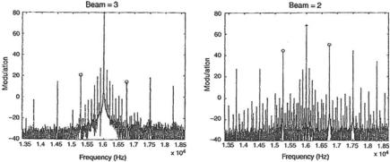
Fig. 10.3 Spectra of signals registered by sensors on the reference beam (left) and on the beam with crack (After Didenkulov et al. [1])
The defects in the concrete beams generate the nonlinear interaction of high frequency and low frequency acoustic waves producing a modulation effect. Figure 10.3 shows the modulation effect revealed by a raising of the lateral frequencies in the spectra of signals from sensors. It can be seen from Fig. 10.3 that the modulation effect is complex. The nonquadratic nonlinearity of the crack produces many lateral frequency components. The difference between levels of the first lateral modulation frequency components and the high frequency components is given by the modulation index. The modulation index can be used as a criterion for nondestructive testing as is shown by measurements done for all the concrete beams.
The experiment shows that the modulation index to depend on the position of a sensor along the testing beam. It is also correlated with the distribution of low frequency modal oscillation along the beam. However, this simple example of the modulation method is not able to detect the positions of cracks in a damaged sample.
10.5Experimental Procedures for the Modulation Mode System
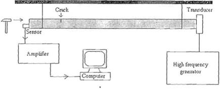
The modulation mode system has to be used in order to detect the crack position in a damaged sample. This is illustrated by an experiment with a metal rod. Figure 10.4 shows the experimental setup.
The duraluminium rod with 2.1 m length was fastened by two ropes to the support. There was a crack at 50 cm from one end of the rod. A high frequency piezoceramic transducer was glued to one end of the rod with a sensor at the other end. This experiment set provided free end-boundary condition to the rod. Continuous longitudinal sound waves at a frequency of about 200 kHz was emitted by the transducer into the rod. The shock of a hammer excited longitudinal resonance mode in the rod. They were generated simultaneously. All the modulation indices can be measured
100 |
10 Modulation Method of Nonlinear Acoustical Imaging |
Fig. 10.4 A scheme of the experiment with a metal rod (After Didenkulov et al. [1])
in a single experiment with such a technique because the spectrum of the registered signal contains modulation frequency components for all the modes. In this experiment, the rod has free boundary conditions at both ends. The same function as in Eq. (10.1) can be used to describe the longitudinal modes in such a sample.
Hence a modified technique is used to reconstruct the crack position in a rod. One M instead of using the parameter M. M is given as
introduces a modified parameter |
˜ |
|
|
|
|
|
|
|
|
|
|
|
˜ |
||||
|
|
|
|
|
|
|
|
|
|
|
|
|
|
|
|
|
|
M (z, z |
0 |
) |
= |
M |
n |
sin k |
|
z |
= |
/ sin k |
|
z |
0 |
/ sin k |
|
z |
(10.5) |
˜ |
|
n |
|
|
n |
|
|
|
|
||||||||
|
|
|
|
|
|
|
|
|
|
|
|
|
|
|
|
||
˜
It can be seen that M is not as positive as M. It has two peaks: one at the crack position z = z0 and the other which is imaginary at position z = l − z0. Equation (10.5) is used for the reconstruction of crack positions in the rod and is given in Fig. 10.5.
10.6 Conclusions
The nonlinear acoustic modulation method can be used for the detection of cracks exhibiting nonlinear properties. The mean modulation method index can be used as a criterion for the detection of damaged sample. The modulation mode method has to be used to detect the crack positions. Based on the measurements of the modulation indices for resonance low frequency modes in the sample, this method allows one to reconstruct a crack position.