

1398 / справочники / DriveSpin_catalogue
.pdfApplications / Anwendungsbeispiele
T |
|
|
S E R I E S |
|
|
E |
|
|
S E R I E S |
|
|
H |
|
|
S E R I E S |
|
|
M |
Other applications |
|
S |
||
Measuring equipment, woodworking |
||
I E |
||
machines, textile machines, packaging |
||
R |
machines, semiconductor manufacturing... |
|
S E |
|
|
|
Andere Anwendungen |
|
|
Messgeräte, holzbearbeitende Maschinen, |
|
|
Textilmaschinen, Packmaschinen, |
|
|
Halbleiterproduktion... |
22
Medical
Medical and rehabilitation devices, scanners, dental replacement grinding machines, other medical equipment...
Medizintechnik
Medizinund Rehabilitationstechnik, Scanners, Zahnersatz Schleifmaschinen, andere medizinische Geräte...

23
S E R I E S
M
S E R I E S
H
S E R I E S
E
S E R I E S
T
Referenzen / References
T S E R I E S E X C E L L E N C E I N P E R F O R M A N C E

S E R I E S
T
Product characteristics / Produktbeschreibung
T
ES IR SE
E
ES IR SE
H
ES IR SE
M
ES IR SE
26
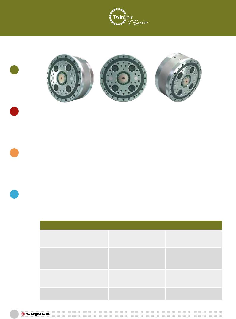
2.1 T SERIES |
2.1 T BAUREIHE |
TheT series represents a wide range of TwinSpin high precision reduction gears with a cylindrical shaped case. The T series high precision reduction gears comprise an accurate reduction mechanism and high-capacity radial and axial cylindrical roller bearings. This design of reduction gears allows the mounting of the load directly on the output flange or the case without a need of additional bearings. The T series high precision reduction gears are characterized by a modular design, which allows the mounting of your desirable type of motor to the reduction gear by means of a motor connection flange. The T series includes TwinSpin high precision reduction gears that are not completely sealed; an inlet flange and a gasket kit have to be used for the sealing. Upon the customer’s request, SPINEA is able to supply a completely sealed reduction gear with a flange according to the customer’s motor.
T Baureihe reprasentiert eine breite Abstufung der hochgenaue TwinSpin Getriebe mit der Zylinderform des Gehauses. Die hochgenaue Getriebe der T Baureihe besteht aus dem genauen Übertragungsmechanismus und der radialaxialen Rollenlager mit der hohen Kapazität zusammen. Diese Konzeption der Getriebe sichert die Festigung der Last direkt an den Ausgangsflansch oder an das Gehause ohne nachsten Zusatzlager. Die hochgenaue Getriebe der T Baureihe zeichnen sich durch die Modularbauweise aus, die ermoglicht, den angeforderten Motortyp zum Getriebe mit dem Eingangsflansch anzuknupfen. Die Präzisionsgetriebe der T Baureihe sind nicht voll abgedichtet. Es ist notwendig, zu der Abdichtung noch einen Eingangsflansch und einen Dichtsatz zu verwenden. Nach dem Bedürfnis kann SPINEA komplett abgedichtete Getriebe mit der gewünschte Motorflanche liefern.
Advantages
•zero-backlash reduction gears
•high moment capacity
•excellent positioning accuracy and positioning repeatibility
•high torsional and tilting stiffness
•small dimensions and weight
•high reduction ratios
•high effeciency
•long lifetime
•easy assembly
Tab.2.1a: T series features / Zusammenfassung - T Baureihe
Vorteile
•spielfreies Getriebe
•hohe Drehmomentkapazitat
•exzellente Positionierungsgenauigkeit und Positionierungswiederholbarkeit
•hohe Torsionsund Kippsteifigkeit
•kompakte Bauform und geringes Gewicht
•hohe Untersetzungen
•hoher Wirkungsgrad
•lange Lebensdauer
•schnelle Montage und einfacher Einbau
Case |
a) TBthreaded holes in the case 1) |
a) TBGewindebohrungen im Getrie- |
|
begehäuse 1) |
|||
b) TCthreaded and through holes in |
|||
Gehäuse |
b) TCGewindeund Durchgangs- |
||
case 2) |
|||
|
bo hrungen im Getriebegehäuse 2) |
||
|
|
||
Input flange connection |
The shaft sealing / adapter flange is |
Wellendichtung / Adapterflansch in |
|
offered in the following versions: |
folgenden Ausführungen: |
||
Direkte Ankupplung an Getriebeadapterflansch |
a) motor connection flange |
a) Motorlaterne |
|
|
b) sealed input cover |
b) abgedichtete Deckelplatte |
|
|
c) without a flange |
c) ohne Flansch je nach Anforderungen |
|
Input shaft design |
The input shaft is offered in the following |
Eingangswelle bietet folgende Ausführun- |
|
|
versions: a) shaft with a keyway |
gen an: |
|
Auslegung der Getriebeadapterflansch |
b) according to a special request |
a) Welle mit Paßfedernut |
|
|
|
b) Spezialwelle |
|
Installation and operation characteristics |
A wider range of modular |
Breite Palette an |
|
Inbetriebnahmeund Betriebsparameter |
configurations |
Modularkonfigurationen |
|
1) Valid for TS 60, TS 70, TS 80, TS 110, TS 140 |
2) Valid for TS 170, TS 200, TS 240, TS 300 |
|
|
1) Gültigkeit für TS 60, TS 70, TS 80, TS 110, TS 140 |
2) Gültigkeit für TS 170, TS 200, TS 240, TS 300 |
||

Ordering specifications / Bestelldaten
Tab.2.1.b: T series ordering specifications / T Baureihe Bestelldaten
TS-200 |
- |
125 |
- |
TC |
- |
P24 |
|
|
....... |
....... |
|
....... |
|
....... |
|
....... |
|
Name |
Size |
|
|
|
Series |
|
Shaft |
|
|
Ratio |
|
version |
|
version |
|
||
Bau- |
Bau- |
|
|
Baureihe |
Welle Ausführung |
|||
|
Untersetzung |
|
||||||
reihe |
größe |
|
|
|
Ausführung |
P (DIN 6885) |
S |
|
|
|
|
|
|
|
|||
|
60 |
|
35, 47, 63 |
|
TB |
6 |
|
• |
|
|
|
|
|||||
|
|
|
|
|
|
|||
|
70 |
|
41, 57, 75 |
|
TB |
11 |
|
• |
|
|
|
|
|
|
|||
|
80 |
|
37, 63, 85 |
|
TB |
8 |
|
• |
|
|
|
|
|
|
|||
|
110 |
|
33, 67, 89, 119 |
|
TB |
14 |
|
• |
|
|
|
|
|
|
|||
TS |
140 |
|
33, 57, 87, 115, 139 |
TB |
19 |
|
• |
|
|
|
|
|
|||||
|
170 |
|
33, 59, 83, 105, 141 |
TC |
24 |
|
• |
|
|
|
|
|
|
||||
|
200 |
|
63, 83, 125, 169 |
|
TC |
24 |
|
• |
|
|
|
|
|
|
|||
|
240 |
|
37, 87, 121, 153 |
|
TC |
28 |
|
• |
|
|
|
|
|
|
|||
|
300 |
|
63, 125, 191 |
|
TC |
28 |
|
• |
|
|
|
|
|
|
|||
|
|
|
|
|
|
|
|
|
Note: An example of an ordering code of a modified TwinSpin T series reduction gear with a motor flange:
TS200 – 125 –TC– P24 – M235 – P231. The markings M235 and P231 for a specific modification are defined by the manufacturer.
Anm.: Das Beispiel der Bezeichnung des TwinSpin Getriebes der T Baureihe mit Motorflansch: TS200 – 125 –TC– P24 – M235 – P231. Die Bezeichnungen M235 und P231 für konkrete Modifikation werden vom Hersteller definiert.
Shaft version / Wellenausführung
T
ES IR SE
E
ES IR SE
H
ES IR SE
M
ES IR SE
P |
Shaft with a keyway |
S |
Special shaft |
|
Welle mit Paßfedernut |
|
Spezialwelle |
27

Technical data / Technische Daten
T
ES IR SE
E
ES IR SE
H
ES IR SE
M
ES IR SE
Tab.2.1c: T series rating table / Leistungsdaten für die Baureihe T
Size Baugröße |
Reduction ratio Untersetzung |
Rated output torque Nennabtriebdrehmoment |
Acceleration and braking torque Beschl. – und Bremsmoment |
Permissible torque at emergency stop Zulässiges Not-Aus-Drehmo- ment |
Rated input speed Nennantriebsdrehzahl |
Cycle effective speed 5) Effektive Antriebsdrehzahl 5) |
Max. allowable input speed10) Max. zulässige Antriebsdrehzahl10) |
Tilting stiffness 1)6) Kippsteifigkeit 1)6) |
Torsional stiffness 1)7) Verdrehsteifigkeit 1)7) |
Max. no-load starting torque 9) Max. Anlaufmoment 9) |
Max. back driving torque 9) Max. Rückdrehmoment 9) |
|
i |
TR [Nm] |
Tmax [Nm] |
Tem [Nm] |
nR [rpm] |
nef[rpm] |
nmax [rpm] |
Mt[Nm/arcmin] |
kt [Nm/arcmin] |
[Nm] |
[Nm] |
|
35 |
|
|
|
|
|
4 000 |
|
|
0,16 |
9 |
TS 60 |
47 |
37 |
74 |
185 |
2 000 |
3 000 |
5 000 |
27 |
3,5 |
0,12 |
9 |
|
63 |
|
|
|
|
|
|
|
0,12 |
10 |
|
|
|
|
|
|
|
|
|
|
|||
|
41 |
|
|
|
|
2 000 |
4 000 |
|
|
0,30 |
11 |
TS 70 |
57 |
50 |
100 |
250 |
2 000 |
2 500 |
5 000 |
35 |
7 |
0,15 |
12 |
|
75 |
|
|
|
|
|
|
0,14 |
13 |
||
|
|
|
|
|
|
|
|
|
|
37 |
|
|
|
|
|
4 000 |
|
|
0,35 |
14 |
|
TS 80 |
63 |
78 |
156 |
390 |
2 000 |
3 000 |
5 000 |
62 |
9 |
0,20 |
15 |
|
|
85 |
|
|
|
|
|
|
|
0,12 |
16 |
||
|
|
|
|
|
|
|
|
|
||||
|
33 |
|
|
|
|
2 000 |
3 500 |
|
|
0,35 |
24 |
|
TS 110 |
67 |
122 |
244 |
610 |
2 000 |
2 500 |
3 900 |
150 |
22 |
0,35 |
28 |
|
89 |
2 000 |
|
0,30 |
30 |
||||||||
|
|
|
|
|
4 500 |
|
|
|||||
|
119 |
|
|
|
|
2 500 |
|
|
0,20 |
33 |
||
|
|
|
|
|
|
|
|
|||||
|
33 |
|
|
|
|
2 000 |
3 000 |
|
|
0,60 |
40 |
|
|
57 |
|
|
|
|
|
3 200 |
|
|
0,40 |
40 |
|
TS 140 |
87 |
268 |
670 |
1 340 |
2 000 |
2 500 |
|
340 |
54 |
0,35 |
55 |
|
|
115 |
|
|
|
|
4 500 |
|
|
0,35 |
65 |
||
|
|
|
|
|
|
|
|
|||||
|
139 |
|
|
|
|
|
|
|
|
0,34 |
65 |
|
|
33 |
|
|
|
|
1 500 |
3 000 |
|
|
2,00 |
75 |
|
|
59 |
|
|
|
|
2 000 |
3 500 |
|
|
2,00 |
85 |
|
TS 170 |
83 |
495 |
1 237 |
2 475 |
2 000 |
|
705 |
102 |
1,40 |
100 |
||
|
|
|||||||||||
|
105 |
|
|
|
|
2 500 |
4 000 |
|
|
1,20 |
125 |
|
|
141 |
|
|
|
|
|
|
|
0,40 |
125 |
||
|
|
|
|
|
|
|
|
|
||||
|
63 |
|
|
|
|
1 500 |
3 500 |
|
|
1,90 |
90 |
|
TS 200 |
83 |
890 |
2 225 |
4 450 |
2 000 |
2 000 |
4 000 |
1 070 |
178 |
1,80 |
120 |
|
125 |
4 000 |
1,70 |
200 |
|||||||||
|
|
|
|
|
|
|
|
|||||
|
169 |
|
|
|
|
2 200 |
4 500 |
|
|
0,90 |
210 |
|
|
37 |
|
|
|
|
1 000 |
2 000 |
|
|
3,00 |
90 |
|
TS 240 |
87 |
1 620 |
4 050 |
8 100 |
1 500 |
|
3 000 |
1 800 |
340 |
1,75 |
160 |
|
121 |
1 500 |
3 500 |
1,70 |
170 |
||||||||
|
|
|
|
|
|
|
||||||
|
153 |
|
|
|
|
|
3 700 |
|
|
1,20 |
180 |
|
|
63 |
|
|
|
|
1 100 |
2 500 |
|
|
3,00 |
200 |
|
TS 300 |
125 |
2 940 |
7 350 |
14 700 |
1 500 |
1 400 |
3 200 |
3 500 |
680 |
2,00 |
250 |
|
|
191 |
|
|
|
|
1 500 |
3 500 |
|
|
1,50 |
300 |
RIGHT TO CHANGE WITHOUT PRIOR NOTICE RESERVED
1/ Mean statistical value. For further information see chapter Torsional stiffness, Tilting stiffness.
2/ Load at output speed 15 rpm. 3/ Tilting moment Mc max
moment.
4/ Axial force Fa max value for Mc=0. If Mc≠0, see chapter Tilting moment.
5/ The effective speed can also be higher for lost motion bigger than 1 arcmin and for low values of oil viscosity. For lost motion lower than 0,6 arcmin please consult the effective speed with the manufacturer.
6/ The parameter depends on the version of the high precision reduction gear.
7/ The parameter depends on the version of the high precision reduction gear, ratio and lost motion.
8/ The values of the parameters are informative. The exact value depends on the specific version of the high precision reduction gear.
9/ Temperatures of the high precision reduction gear lower than 20°C will cause higher no-load starting or back driving torque.
10/ Depends on the duty cycle; a higher input speed may still be possible; please consult the manufacturer.
DAS RECHT ZU ÄNDERUNGEN OHNE VORHERIGE MITTEILUNG VORBEHALTEN
1)Statistischer Mittelwert. Für weitere Angaben über die Verdrehsteifigkeit siehe Kapitel Kippsteifigkeit und Verdrehsteifigkeit.
2)Belastung der Abtriebswelle bei Ausgangsdrehzahl von 15 U/m.
3)Kippmoment Mc max für Fa=0. Wenn Fa≠0, siehe Kapitel Kippmoment.
4)Axialkraft Fa max für Mc=0. Wenn Mc≠0, siehe Kippmoment.
5)Effektive Antriebsdrehzahl kann für Lost Motion größer als 1 arcmin und für niedrige Werte der Ölviskosität auch höher werden. Für ein Wert von Lost Motion kleiner als 0,6 arcmin, bitte, setzen Sie sich in Kontakt im Bezug auf effektive Antriebsdrehzahl mit dem Hersteller.
6)Parameter hängt von der Präzisionsgetriebeausführung ab.
7)Parameter hängt von der Präzisionsgetriebeausführung, Untersetzung und Lost Motion ab.
8)Der Wert einzelner Parameter dient nur zur Information. Genaue Werte hängen von der jeweiligen Präzisionsgetriebeausführung ab.
9)Niedrigere Temperatur als 20°C des Getriebegehäuses wird ein Anstieg des Anlaufsmomentes oder Rückdrehmoment zur Folge haben.
10)In Abhängigkeit von der Einschaltdauer ist höhere Eingangsdrehzahl immer möglich, bitte, setzen Sie sich mit dem Hersteller in Verbindung.
28

Technical data / Technische Daten
Tab.2.1c: Continued / Fortgesetzt
Size Baugröße |
Reduction ratio Untersetzung |
Max. lost motion Max. Lost Motion |
Average angular transmission error 1)7) Drehwinkeübertragungsgenauigkeit1)7) |
Hysteresis Hysterese |
Max. tilting moment 2)3) Max. Kippmoment 2)3) |
Rated radial force 2) Nennradialkraft 2) |
Max. axial force 2)4) Max. Axialkraft 2)4) |
Input inertia 8) Massenträgheitsmoment am Eingang 8) |
Weight 8) Gewicht8) |
|
|
i |
LM [arcmin] |
ATE [arcsec] |
H [arcmin] |
M c max [Nm] |
F rR [kN] |
F a max [kN] |
l [10-4 kgm2] |
m [kg] |
|
|
35 |
|
|
|
|
|
|
|
|
|
TS 60 |
47 |
<1,5 |
±36 |
<1,5 |
107 |
2,6 |
3,7 |
0,006 |
0,86 |
|
|
63 |
|
|
|
|
|
|
|
|
|
|
41 |
|
|
|
|
|
|
|
|
|
TS 70 |
57 |
<1,5 |
±36 |
<1,5 |
142 |
2,8 |
4,1 |
0,061 |
1,05 |
|
|
75 |
|
|
|
|
|
|
|
|
|
|
37 |
|
|
|
|
|
|
|
|
|
TS 80 |
63 |
<1,5 |
±36 |
<1,0 |
280 |
4,8 |
6,9 |
0,03 |
1,64 |
|
|
85 |
|
|
|
|
|
|
|
|
|
|
33 |
|
|
|
|
|
|
|
|
|
TS 110 |
67 |
<1,0 |
±20 |
<1,0 |
740 |
9,3 |
13,1 |
0,16 |
3,76 |
|
89 |
||||||||||
|
|
|
|
|
|
|
|
|
||
|
119 |
|
|
|
|
|
|
|
|
|
|
33 |
|
|
|
|
|
|
|
|
|
|
57 |
|
|
|
|
|
|
|
|
|
TS 140 |
87 |
<1,0 |
±20 |
<1,0 |
1 160 |
11,5 |
17 |
0,67 |
6,45 |
|
|
115 |
|
|
|
|
|
|
|
|
|
|
139 |
|
|
|
|
|
|
|
|
|
|
33 |
|
|
|
|
|
|
|
|
|
|
59 |
|
|
|
|
|
|
|
|
|
TS 170 |
83 |
<1,0 |
±20 |
<1,0 |
2 430 |
19,2 |
27,9 |
1,15 |
11,07 |
|
|
105 |
|
|
|
|
|
|
|
|
|
|
141 |
|
|
|
|
|
|
|
|
|
|
63 |
|
|
|
|
|
|
|
|
|
TS 200 |
83 |
<1,0 |
±18 |
<1,0 |
3 300 |
21,1 |
31,7 |
2,6 |
17,23 |
|
125 |
||||||||||
|
|
|
|
|
|
|
|
|
||
|
169 |
|
|
|
|
|
|
|
|
|
|
37 |
|
|
|
|
|
|
|
|
|
TS 240 |
87 |
<1,0 |
±18 |
<1,0 |
5 720 |
30,8 |
47,3 |
3,9 |
31,15 |
|
121 |
||||||||||
|
|
|
|
|
|
|
|
|
||
|
153 |
|
|
|
|
|
|
|
|
|
|
63 |
|
|
|
|
|
|
|
|
|
TS 300 |
125 |
<1,0 |
±18 |
<1,0 |
12 000 |
45,3 |
68,1 |
11,2 |
55,73 |
|
|
191 |
|
|
|
|
|
|
|
|
|
Important notes: |
|
|
|
|
Hinweis: |
|
|
|
|
|
• Load values in the table are valid for the nominal life of |
|
• Belastungswerte in Tabelle beziehen sich auf eine |
|
|||||||
L10 =6000 [Hrs]. |
|
|
|
|
nominelle Lebensdauer L10 =6000 St. |
|
|
|||
• High precision reduction gears are preferred for |
|
• Prazisionsgetriebe ist fur die Betriebsart S3-S8 |
|
|||||||
intermittent cycles (S3-S8); the output speed in applications is |
ausgelegt, Ausgangsdrehzahl ist variabel in beiden |
|
||||||||
inverted-variable. The continuous mode cycle (S1) is needed |
Drehrichtungen. Die Betriebsart S1 sollte moglichst mit |
|
||||||||
to be consulted with the manufacturer. |
|
|
dem Hersteller besprochen werden. |
|
|
|||||
• Dimensional pictures of the T series reduction gears are |
• T- Baureihe des Prazisionsgetriebes ist im Katalog ohne |
|
||||||||
listed in the catalogue without sealing. |
|
|
Dichtungssatz aufgefuhrt. |
|
|
|||||
• Sealing options are decribed in chapter Assembly |
|
• Abdichtungsmoglichkeiten sind im Kapitel |
|
|||||||
instructions. |
|
|
|
|
Montageanweisungen beschrieben. |
|
|
|||
• Please consult the the maximum speed in a duty cycle |
|
• Maximale Zyklusantriebsdrehzahl besprechen Sie, bitte, |
|
|||||||
with the manufacturer. |
|
|
|
moglichst immer mit dem Hersteller. |
|
|
||||
• The values in the table refer to the nominal operating |
|
• Werte in grafischen Darstellungen beziehen sich auf die |
|
|||||||
temperature. |
|
|
|
|
Betriebstemperatur. |
|
|
|
||
The ratios highlighted in bold are recommended by SPINEA as optimal versions in terms of price and delivery.
Das angestrichene Untersetzungsverhältnis wird von der Firma SPINEA als eine optimale Version aus der Sicht des Preises und der Lieferung empfohlen.
T
ES IR SE
E
ES IR SE
H
ES IR SE
M
ES IR SE
29

30 |
S E R I E S |
M |
S E R I E S |
H |
S E R I E S |
E |
S E R I E S |
T |
TS 60 - i - TB - P6
1. Use only standardized components, such as ring seals, bolts, washers, etc. / 1. Benutzen Sie nur standardisierte Komponente wie zum Beispiel O-Ring, Dichtungen, Schrauben, Scheiben, usw.
2. Right to change without prior notice reserved. / 2. Recht auf die Änderungen ohne vorherige Ankündigung ist vorbehalten.
3. Unsealed space, see the installation instructions in the TS Catalogue. / 3. Unabgedichtete Raum, sieh das Montagemanual im TS Katalog.
i - 60 TS |
Drawings |
P6 - TB - |
Zeichnungen / |
|
|

TS 70 - i - TB - P11
1. Use only standardized components, such as ring seals, bolts, washers, etc. / 1.Benutzen Sie nur standardisierte Komponente wie zum Beispiel O-Ring, Dichtungen, Schrauben, Scheiben, usw.
2. Right to change without prior notice reserved. / 2.Recht auf die Änderungen ohne vorherige Ankündigung ist vorbehalten.
3. Unsealed space, see the installation instructions in the TS Catalogue. / 3. Unabgedichtete Raum, sieh das Montagemanual im TS Katalog.
31 |
S E R I E S |
M |
S E R I E S |
H |
S E R I E S |
E |
S E R I E S |
T |
70 TS |
Drawings |
P11 - TB - i - |
Zeichnungen / |
|
|