

1398 / справочники / DriveSpin_catalogue
.pdfAssembly / Einbauanleitung
5.2.4 E series mounting tolerances |
5.2.4 Die Einbautoleranzen – E Baureihe |
The requirements for circumferential and face runout in the case |
Die Anforderungen auf Umfangsund Stirnrundlauf bei der direkten |
of a direct connection of the high precision reduction gear with |
Verknüpfung des hochgenauen Getriebes und des Servoantriebs, |
a servomotor whose shaft is of the precision in accordance with |
dessen Welle in der Genauigkeit mit der Norm DIN 42955R überein- |
DIN 42955R are specified in Fig. 5.2.4. The tolerances are specified |
stimmt, sind auf der Abb. Nr. 13 zu finden. Die Toleranzwerte gibt die |
in Tab. 5.2.4. |
Abb.5.2.4. |
Fig. 5.2.4: Geometric deviations for the connection of the E series TwinSpin high precision reduction gear flange with a motor or of the TwinSpin E series reduction gear
Die geometrischen Abweichungen für die Verknüpfung des Flansches des hochgenaue TwinSpin Getriebes der E Baureihe mit dem Motor, bzw. des TwinSpin Getriebes der E Baureihe
122

Assembly / Einbauanleitung
Tab 5.2.4: Tolerances of circumferential and face runout in the case of a direct connection of TwinSpin high precision reduction gears with a servomotor according to DIN 42955 R [mm]
Die Toleranzen des Umfangsund Stirnrundlaufs bei der direkten Verknüpfung der hochgenaue TwinSpin Getriebe mit dem Servoantrieb nach DIN 42955 R [mm]
Type |
a |
b |
C |
T1 |
T2 |
U |
T |
Z |
V |
TS 70 |
0,015 |
0,04 |
0,038 |
0,05 |
0,05 |
0,010 |
0,007 |
0,020 |
0,025 |
TS 80 |
0,015 |
0,05 |
0,038 |
0,06 |
0,05 |
0,010 |
0,007 |
0,020 |
0,025 |
TS 110 |
0,018 |
0,05 |
0,044 |
0,07 |
0,06 |
0,010 |
0,008 |
0,025 |
0,025 |
TS 140 |
0,021 |
0,05 |
0,05 |
0,07 |
0,06 |
0,010 |
0,009 |
0,025 |
0,030 |
TS 170 |
0,021 |
0,05 |
0,05 |
0,07 |
0,06 |
0,015 |
0,010 |
0,025 |
0,030 |
TS 200 |
0,025 |
0,05 |
0,058 |
0,07 |
0,06 |
0,015 |
0,010 |
0,035 |
0,030 |
TS 220 |
0,025 |
0,063 |
0,058 |
0,08 |
0,06 |
0,015 |
0,013 |
0,030 |
0,035 |
Fig. 5.2.4a: Tolerances of circumferential and face runout in the case of direct connection of TwinSpin high precision reduction gears with a servomotor according to DIN 42955 R
Die Toleranzen des Umfangsund Stirnrundlaufs bei der direkten Verknüpfung der hochgenauen TwinSpin
Getriebe mit dem Servoantrieb nach DIN 42955 R
123

Assembly / Einbauanleitung
5.2.5E series tightening torques of connecting bolts
For the safe transmission of external loads applying on the TwinSpin high precision reduction gear, it is required to use connecting screws of the 10K grade and to degrease contact surfaces of friction joints before installation. Tightening torques of the screws are shown in Tab.5.2.5a.
Allowable torque transmitted through the connecting screws on the flange and case are shown in Tab.5.2.5b.
5.2.5 Die Drehmomente der Anschlußschrauben E Baureihe
Um eine sichere Übertragung der Außenbelastung auf das hochgenaue TwinSpin Getriebe zu erreichen, ist es erforderlich, die Anschlußschrauben der Qualität 10K zu verwenden und die Auflageflächen der Reibanschlusse vor der Montage abzufetten. Die Drehmomente der Schrauben zeigt die Tabelle.5.2.5a.
Die Tabelle zeigt das erlaubte Drehmoment, das durch Anschlußschrauben auf dem Flansch und dem Gehäuse übertragen wird Tabelle 5.2.5b.
Tab. 5.2.5a: Tightening torques of screws / Die Drehmomente der Schrauben
Screw |
Tightening torque [Nm] |
Clamping force [N] |
Screw material class specification |
Schraube |
Drehmoment [Nm] |
Klemmkraft [N] |
Spezifikation der Festigkeit des Schraubenmaterials |
M3 |
1.9 |
3 100 |
|
M4 |
4,3 |
5 300 |
|
M5 |
8.4 |
8 800 |
|
M6 |
14 |
12 400 |
|
M8 |
35 |
22 750 |
ISO 898 T1 10.9 or / oder 12.9 |
M10 |
70 |
36 200 |
|
M12 |
122 |
52 900 |
|
M16 |
300 |
100 000 |
|
M18 |
455 |
120 000 |
|
Tab. 5.2.5b: Allowable torques transmitted through connecting crews / Das durch die Anschlußschrauben übertragbare und erlaubte Drehmoment
|
Output flange / Ausgangsflansch |
|
Case / Gehäuse |
|
|||
|
|
Pitch diameter |
Transmitted torque |
|
Pitch diameter |
Transmitted torque |
|
Size |
Number x screw |
[mm] |
[Nm] |
Number x screw |
[mm] |
[Nm] |
|
Zahl x Schraube |
Teilungsdurchschnitt |
Übertragbares |
Zahl x Schraube |
Teilungsdurchschnitt |
Übertragbares |
||
Grösse |
|||||||
|
[mm] |
Moment [Nm] |
|
[mm] |
Moment [Nm] |
||
|
|
|
|||||
TS 70 |
5xM6 |
40 |
186* |
10xM5 |
76 |
500 |
|
TS 70 |
5xM6 |
40 |
254* |
10xM5 |
76 |
500 |
|
with pin Ø6 |
40 |
||||||
|
|
|
|
|
|||
TS 80 |
8xM5 |
46 |
242* |
10xM5 |
85 |
560 |
|
TS 110 |
14xM6 |
69 |
890 |
14xM5 |
113 |
1040 |
|
TS 140 |
18xM6 |
92 |
2090 |
12xM6 |
140 |
1560 |
|
8xM6 |
74 |
||||||
|
|
|
|
|
|||
TS 170 |
18xM8 |
110 |
4470 |
14xM8 |
175 |
4180 |
|
8xM8 |
80 |
||||||
|
|
|
|
|
|||
TS 200 |
18xM12 |
129 |
9880 |
14xM10 |
206 |
7830 |
|
8xM6 |
91 |
||||||
|
|
|
|
|
|||
TS220 |
20xM10 |
140 |
7600 |
14xM10 |
220 |
8350 |
|
*Safe transmission of the the torque requires glue to be applied on the friction surfaces (NICRO 20-10, NICRO 32-02; LOCTITE 603)
*Für sichere Momentübertragung müssen die Reibflächen geklebt werden (NICRO 20-10, NICRO 32-02; LOCTITE 603)
124

Assembly / Einbauanleitung
5.3.1 Examples of mounting H series
The H series is completely sealed and filled with grease for its lifetime. Figs. 5.3.1a, 5.3.1b and 5.3.1c show examples of connections with motors.
The through input shaft of the H series high precision reduction gear with an enlarged diameter allows to pass energy supply or control cables through the axis of the reduction gear to devices mounted behind the output flange. The H series reduction gear is most often used in combination with a pre-stage, which may comprise gears or toothed belt drives. A typical example of the H series reduction gear drive through a toothed belt is shown in Fig. 5.3.1a. The driven pulley is attached to the shaft of the reduction gear with screws, which have to be tightened with a tightening torque according to Tab. 5.3.4a and Tab.5.3.4b.
The driving pulley with the motor must be shiftable to allow the tightening of the belt.
Fig 5.3.1b shows the drive of the input shaft through gears. The gears are housed in a frame, which is part of the reduction gear‘s input flange.
Fig. 5.3.1c shows a toothed pulley mounted on the input flange by means of friction rings.
5.3.1 Beispiele der Einbau der H Baureihe
H Baureihe ist die völlig abgedichtete Baureihe, die mit der Fettfül -lung auf die ganze Lebensdauert ausgestattet ist. Die Abbildungen 5.3.1a, 5.3.1b und 5.3.1c zeigen die Beispiele der Verknüpfungen mit Motors.
Die vorläufige Eingangswelle des hochgenaue Getriebes der H Baureihe mit dem vergrößerten Durchschnitt ermöglicht die Leitung der energetischen, bzw. der leitenden Verteiler durch die Getriebsachsel zu den hinter dem Ausgangsflansch befestigten Ausrüstungen. Das Getriebe der H Baureihe wird am häufigsten zusammen mit dem Vorbild verwendet, das von den verzahnten Räder, bzw. den verzahnten Riemenübersetzungen zusammengesetzt wird.
Den typischen Beispiel des Antriebs des Getriebes der H Baureihe mit der Zahnriemenübersetzung zeigt die Abb. Nr. 5.3.1a.
Die angetriebene Riemenscheibe zur Getriebswelle ist mit den Anschlußschrauben befestigt, die nach der Tabelle Nr.5.3.4a, Tab.5.3.4b mit dem Drehmoment befestigt werden müssen. Die angetriebene Riemenscheibe mit dem Motor muss schiebbar sein, damit die Spannung des Riemens möglich ist.
Die Abb. 5.3.1b zeigt den Antrieb der Eingangswelle mit Hilfe der verzahnten Räder. Die verzahnten Räder des Vorbildes sind in dem Schrank gelegt, der ein Zusammenteil der Eingangswelle des Getriebes bildet.
Die Abb. 5.3.1c zeigt die Festigung der verzahnten Riemenscheibe auf die Eingangswelle mit Hilfe der Reibungsringe.
Fig. 5.3.1a: Connection of a toothed pulley with the reduction gear shaft by means of a screw connection
Die Verknüpfung mit dem verzahnten Riemen
125

Assembly / Einbauanleitung
Fig. 5.3.1b: Connection of a toothed pulley with the reduction gear shaft by means of a friction connection
Die Verknüpfung mit den verzahnten Rädern
Fig. 5.3.1c: Connection of a gear wheel with the reduction gear shaft by means of a screw connection
Die Verknüpfung mit dem verzahnten Riemen und der Reibmaschine
126

Assembly / Einbauanleitung
5.3.2 H series installation procedure
Prior to the installation, wipe off the protective oil film from the reduction gear’s surface with a clean and dry cloth. Degrease the contact surfaces of the friction-type of connections. TwinSpin high precision reduction gears are not protected against corrosion. Please, contact the Sales Department or your local Spinea sales representative for further information.
5.3.2 Die Einbauprozedur H Baureihe
Vor der Montage ist die Konservierungsölschicht auf der Oberfläche des Getriebes mit einem reinen und nicht fusselnden Tuch abzuwischen. Die Kontaktoberflächen zu anderen Bauteilen sollten leicht gefettet werden.Die hochgenauen TwinSpin Getriebe sind korrosiongeschützt. Für die meisten Servomotoren bieten wir, bei Nachfrage, entsprechende Einbauflanschen, bitte, setzen Sie sich mit der Vertriebsabteilung oder unseren lokalen Vertriebsvertretungen in Verbindung.
5.3.3 H series mounting tolerances |
5.3.3 Die Einbautoleranzen H Baureihe |
Fig.: 5.3.3: Maximum geometric deviations for the H series reduction gear
Maximale geometrische Abweichungen für das Getriebe der H Baureihe
Tab. 5.3.3a: Maximum geometric deviations for the H series reduction gear [mm]
Die Tabelle der maximalen geometrischen Abweichungen für das Getriebe der H Baureihe [mm]
|
TS 140H |
TS 170H |
TS 200H |
TS 220H |
T |
0,02 |
0,02 |
0,02 |
0,02 |
T1 |
0,013 |
0,015 |
0,015 |
0,015 |
Z |
0,025 |
0,025 |
0,03 |
0,03 |
Z1 |
0,015 |
0,015 |
0,02 |
0,02 |
V |
0,05 |
0,05 |
0,06 |
0,06 |
127

Assembly / Einbauanleitung
5.3.4H series tightening torques of connecting screws
For the safe transmission of external loads applied to the TwinSpin high precision reduction gear, it is required to use connecting screws of the 10k grade and to degrease contact surfaces of friction joints before the installation. Tightening torques of screws are shown in Tab. 5.3.4a. Allowable torques transmitted through connecting screws on the flange and case are shown in Tab. 5.3.4b.
5.3.4Die Drehmomente der Anschlußkupplungen der H Baureihe
Um eine sichere Übertragung der Außenbelastung auf das hochgenaue TwinSpin Getriebe zu erreichen, ist es erforderlich, die Anschlußschrauben der Qualität 10K zu verwenden und die Auflageflächen der Reibanschlusse vor der Montage abzufetten. Die Drehmomente der Schrauben zeigt die Tab.5.3.4a. Die Tab. Nr.5.3.4b zeigt das erlaubte Drehmoment, das durch Anschlußschrauben auf dem Flansch und dem Gehäuse übertragen wird.
Tab. 5.3.4a: Tightening torques of screws / Die Drehmomente der Schrauben
Screw |
Tightening torque [Nm] |
Clamping force [N] |
Screw material class specification |
Schraube |
Drehmoment [Nm] |
Klemmkraft [N] |
Spezifikation der Festigkeit des Schraubenmaterials |
M3 |
1.9 |
3 100 |
|
M4 |
4,3 |
5 300 |
|
M5 |
8.4 |
8 800 |
|
M6 |
14 |
12 400 |
|
M8 |
35 |
22 750 |
ISO 898 T1 10.9 or / oder 12.9 |
M10 |
70 |
36 200 |
|
M12 |
122 |
52 900 |
|
M16 |
300 |
100 000 |
|
M18 |
455 |
120 000 |
|
Tab. 5.3.4b: Allowable torques transmitted through connecting screws
DurchVerbindungsschrauben übertragbares Drehmoment
|
Output flange / Ausgangsflansch |
|
Case / Gehäuse |
|
|||
|
|
Pitch diameter |
Transmitted torque |
|
Pitch diameter |
Transmitted torque |
|
Size |
Number x screw |
[mm] |
[Nm] |
Number x screw |
[mm] |
[Nm] |
|
Zahl x Schraube |
Teilungsdurchschnitt |
Übertragbares |
Zahl x Schraube |
Teilungsdurchschnitt |
Übertragbares |
||
Grösse |
|||||||
|
[mm] |
Moment [Nm] |
|
[mm] |
Moment [Nm] |
||
|
|
|
|||||
TS 70 |
5xM6 |
40 |
186* |
8xM5 |
76 |
400 |
|
|
5xM6 |
40 |
|
|
|
|
|
TS 70 |
|
|
254* |
8xM5 |
76 |
400 |
|
|
with pin Ø6 |
40 |
|
|
|
|
|
TS 140 |
16xM6 |
92 |
1 400 |
12xM6 |
140 |
1 560 |
|
TS 170 |
18xM8 |
110 |
3 300 |
12xM8 |
175 |
3 580 |
|
TS 200 |
18xM12 |
131 |
6 400 |
12xM10 |
206 |
6 700 |
|
TS 220 |
20xM10 |
140 |
7 600 |
12xM10 |
220 |
7 100 |
|
*The safe transmission of the torque requires glue to be applied on the friction surfaces (NICRO 20-10, NICRO 32-02; LOCTITE 603)
*Für sichere Momentübertragung müssen die Reibflächen geklebt werden (NICRO 20-10, NICRO 32-02; LOCTITE 603)
128

Assembly / Einbauanleitung
5.4 Examples of M series installations
In order to achieve the maximum performance of the TwinSpin high precision reduction gear, it is important to pay attention to the installation and accuracy of the assembly and lubrication. The M series high precision reduction gears are completely sealed. The modular design of the reduction gear allows the connection of different drive parts. Motor flanges and shaft couplings are required for this connection. We can design and supply such parts upon request together with a reduction gear.
5.4 Beispiele der Einbau der M Baureihe
Um die maximale Leistung des hochgenaue TwinSpin Getriebes zu erreichen, ist es wichtig, die Aufmerksamkeit der Einbau, der Genauigkeit der Montage und der Schmierung zu widmen. Die hochgenauen Getriebe der M Baureihe sind völlig abgedichtet. Die Bausteinkonstruktion des Getriebes ermöglicht den Anschluß der unterschiedlichen Antriebsteilen. Dazu ist es notwendig, die Motorflanschs und Wellekupplungen zu benutzen. Wir sind fähig, den Vorschlag und die Bauteile auf Ihren Wunsch zusammen mit dem Getriebe zu liefern.
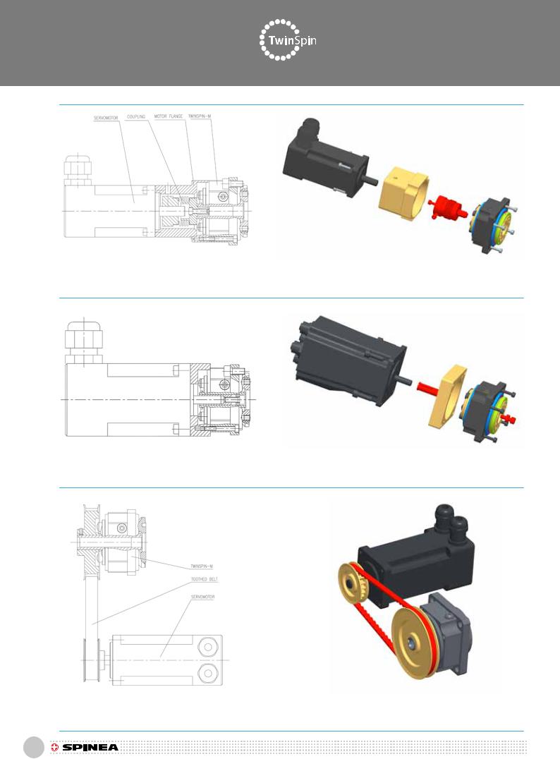
5.4.1. Examples of M series installations
The most common cases of connections between the M series TwinSpin high precision reduction gear and a servomotor are shown on Fig. 5.4.1a, Fig. 5.4.1b, Fig. 5.4.1c, and Fig. 5.4.1d.
Direct connection of the shaft of the high precision reduction gear with a motor through a keyway. This connection requires that the motor shaft has the same diameter as the hole in the high precision reduction gear. In the case of direct connection of the reduction gear with a motor, all specified tolerances for the coupling flange must be met and only motors with shafts that that meet the tolerances specified in the European DIN 42955 standard may be used. The Sales Department will provide you with information on such standards or will provide technical assistance for your specific application.
5.4.1 Beispiele der Einbau der M Baureihe
Am häufigsten gibt es die Fälle der Verknüpfung mit dem hochgenaue Getriebe der M Baureihe und den Servomotors, siehe die Abb. Nr. 5.4.1a, 5.4.1b, 5.4.1c und 5.4.1d. Die direkte Verknüpfung der Welle des hochgenaue Getriebes mit dem Motor mit Hilfe des Federnuts. Die genannte Verknüpfung erfordert dieselben Durchschnitte der Motorwelle und der Bohrung im hochgenaue Getriebe. Bei der direkten Verknüpfung der Getriebe mit dem Motor müssen die vorgeschriebenen Toleranzen des Anschlußflansches erhalten werden und die geeigneten Motors verwendet werden, dessen Wellentoleranzen die Kriterien nach der europäischen Norm DIN 42955 erfüllen. Die Geschäftsabteilung gibt Ihnen die Informationen von diesen Normen oder für die konkreten Applikation kann Ihnen auch Hilfe geleistet werden.
Fig.5.4.1a: Shaft connection with a keyway / Obr.5.4.1a: Die Verknüpfung der Wellen mit dem Federnut
129
Assembly / Einbauanleitung
Fig.5.4.1b: Shaft connection with a flexible coupling / Die Verknüpfung der Welle mit der flexiblen Kupplung
Fig.5.4.1c: Shaft connection with a collet / Die Verknüpfung der Wellen mit dem Deckenanker
Fig.5.4.1d: Example of the use of the hollow-shaft version of the reduction gear, driven through a toothed belt
Der Beispiel der Verwendung der Hollowshaft Version des durch verzahnten Riemen angetriebenen Getriebe
130

Assembly / Einbauanleitung
5.4.2 Installation procedure |
5.4.2 Die Einbauprozedur |
A typical example of an assembly with TS 50 is shown on Fig. 5.4.2. Before the installation, it is desirable to wipe off the protective oil film from the surface of the reduction gear by a clean and dry cloth. Contact surfaces of friction joints must be degreased prior to the installation. When cleaning, make sure that the degreaser does not get into the reduction gear. During the installation, proceed with the following steps: first, fasten a coupling to the reduction gear, then the connecting flange, to which mount the motor and then bolt the whole assembly to the frame.
Den typischen Beispiel der Baugrupppe mit TS 50 zeigt die Abb. 5.4.2. Es ist wichtig, vor der Einbau die konservierende Ölschicht von der Oberfläche des Getriebes mit einem trockenen Reintuch abtrocknen. Die Auflageflächen der Reibmaschinen müssen vor der Montage entfettet werden. Bei der Reinigung soll daran geachtet werden, dass das Entfettungsmittel nicht ins Getriebe gelangt. Bei der Einbau soll der folgende Fortgang erhalten werden: Die Kupplung wird zuerst zum Getriebe gefestigt, danach kommt der Anschlußflansch zum Motor und letztens wird die ganze Baugruppe zum unbeweglichen Maschinenteil gefestigt.
Fig. 5.4.2: Typical connection of a motor to the M series TS reduction gear
Typischer Anschluß des Motors zum Getriebe TwinSpin der M Baureihe
131