

1398 / справочники / DriveSpin_catalogue
.pdfAssembly / Einbauanleitung
5.1.3 Dimensions and tolerances |
|
|
5.1.3 Masse und Toleranzen der |
|
|||||||||
of the T series connecting parts example |
|
Anbauteile T Baureihe Beispiel |
|||||||||||
|
|
|
|||||||||||
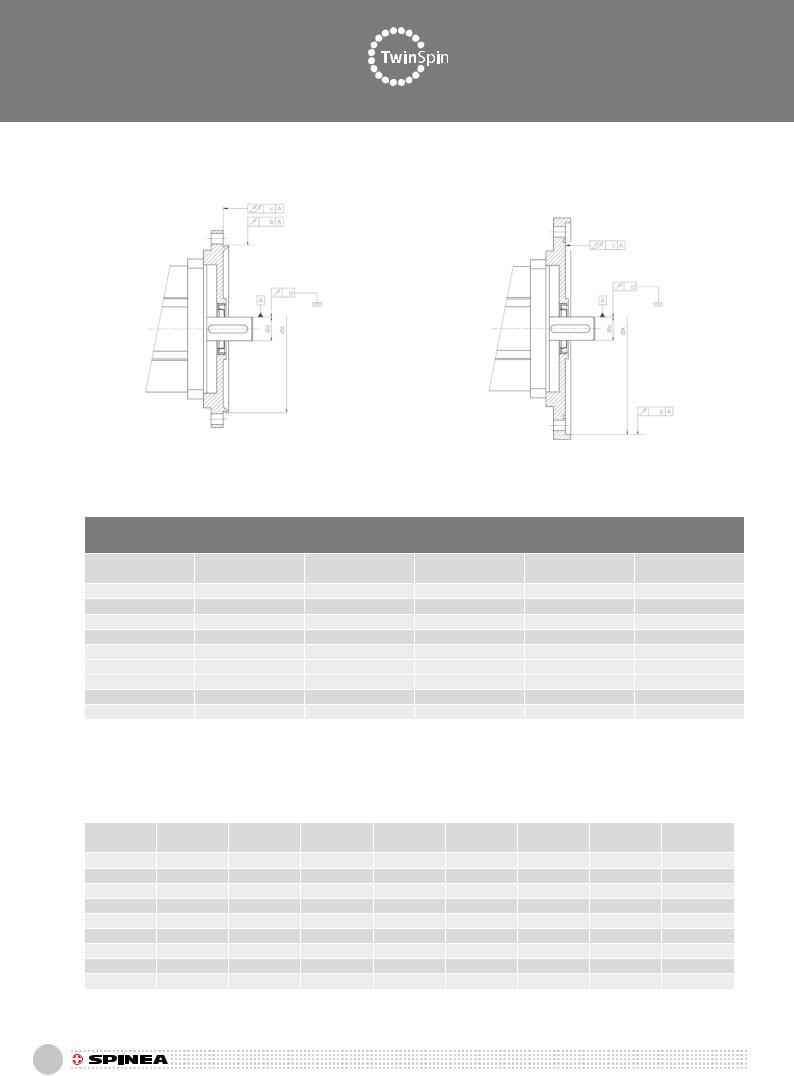
Tab. 5.1.3a: Dimension table of input and output flanges of the TwinSpin T series reduction gears [in mm] Fig. 5.1.3a |
|
|
|||||||||||
|
Abmessungstafel für Antriebs-und Abtriebsflansche der TwinSpin Ausführungen T Baureihe [mm] nach (Abb) 5.1.3a |
|
|||||||||||
|
|
|
|
|
|
|
|
|
|
|
|
|
|
Type |
ØA g6 |
ØB2 |
ØB h9 |
ØC+0,1 |
ØD |
ØE |
ØF H8 |
ØG |
ØH |
ØJ j6 |
ØK+0,2 |
ØL |
|
TS 60 |
- |
69 |
49,2 |
|
- |
- |
- |
- |
57 |
12,5 |
15,5 |
18 |
42 |
TS 70 |
59,3 |
- |
57,9 |
|
57,9 |
34 |
28 |
30 |
64 |
22 |
26 |
- |
42 |
TS 80 |
- |
86 |
65 |
|
- |
- |
- |
- |
73 |
18 |
22,3 |
25 |
69 |
TS 110 |
93 |
- |
90 |
|
90 |
36 |
29 |
32 |
100 |
24 |
32 |
33 |
69 |
TS 140 |
119 |
- |
116 |
|
112 |
48 |
39 |
42 |
127 |
34 |
42 |
43 |
92 |
TS 170 |
145 |
- |
142 |
|
138 |
54 |
44 |
47 |
156 |
39 |
47 |
48 |
110 |
TS 200 |
170 |
- |
167 |
|
167 |
62 |
48 |
52 |
183 |
43 |
52 |
53 |
131 |
TS 240 |
- |
250 |
201,3 |
|
- |
- |
- |
- |
220 |
47 |
57 |
60 |
110 |
TS 300 |
- |
312 |
249,6 |
|
- |
- |
- |
- |
274 |
50 |
60 |
66 |
131 |
Type |
ØN |
ØP H7 |
ØR |
|
ØS |
ØT |
A1 |
A2 |
A3 |
A4 |
B1 |
B2 |
B3 |
TS 60 |
4,3 |
63 |
51 |
|
57 |
3,2 |
- |
- |
R 0,2 |
R 0,3 |
- |
- |
0,5x45° |
TS 70 |
4,3 |
70 |
58 |
|
64 |
3,2 |
R 2 |
R 0,8 |
- |
- |
0,3x45° |
0,3x45° |
0,3x45° |
TS 80 |
5,3 |
80 |
65 |
|
73 |
4,3 |
- |
- |
R 0,3 |
R 0,3 |
- |
- |
0,5x45° |
TS 110 |
6,4 |
110 |
88 |
|
100 |
5,3 |
R 0,8 |
R 0,8 |
R 0,2 |
- |
0,3x45° |
0,5x45° |
0,5x45° |
TS 140 |
6,4 |
140 |
115 |
|
127 |
6,4 |
R 0,8 |
R 0,8 |
R 0,2 |
- |
0,5x45° |
0,5x45° |
0,5x45° |
TS 170 |
8,4 |
170 |
140 |
|
156 |
8,4 |
R 0,8 |
R 0,8 |
R 0,3 |
- |
0,5x45° |
0,5x45° |
0,5x45° |
TS 200 |
10,5 |
200 |
165 |
|
183 |
10,5 |
R 0,8 |
R 0,8 |
R 0,3 |
- |
0,5x45° |
0,5x45° |
0,5x45° |
TS 240 |
13 |
240 |
201 |
|
220 |
12 |
- |
- |
R 0,4 |
R 0,4 |
- |
- |
0,5x45° |
TS 300 |
17 |
300 |
248 |
|
274 |
16 |
- |
- |
R 0,4 |
R 0,4 |
- |
- |
0,5x45° |
Type |
C1+0,2 |
C2 |
C3 |
|
E1 H12 |
E2 |
|
E3 |
F2 |
F3 |
G1-0,1 |
G2 |
G3+0,05 |
TS 60 |
- |
2 |
4 |
|
3,2 |
1,5 |
|
3 |
- |
R 0,5 |
- |
7,5 |
0,7 |
TS 70 |
1,4 |
0,7 |
5 |
|
3,2 |
1,5 |
|
5 |
2,7 |
R 0,5 |
2,8 |
5 |
- |
TS 80 |
- |
1,5 |
4 |
|
4,3 |
1,5 |
|
3 |
- |
R 0,5 |
- |
6 |
1,1 |
TS 110 |
2 |
0,7 |
5 |
|
5,3 |
1,5 |
|
5 |
4,5 |
R 0,5 |
3,5 |
6 |
0,7 |
TS 140 |
2 |
0,7 |
5 |
|
6,4 |
1,5 |
|
5 |
2 |
R 0,5 |
3,5 |
6 |
0,7 |
TS 170 |
2 |
1 |
5 |
|
8,4 |
1,5 |
|
5 |
3,5 |
R 0,5 |
3,5 |
7 |
1,1 |
TS 200 |
2,5 |
2 |
5 |
|
10,5 |
1,5 |
|
5 |
5,5 |
R 0,8 |
5,5 |
7,5 |
1,1 |
TS 240 |
- |
- |
6 |
|
13 |
1,5 |
|
4,5 |
- |
R 0,5 |
- |
7,5 |
1,5 |
TS 300 |
- |
- |
6 |
|
17 |
1,5 |
|
5 |
- |
R 0,5 |
- |
8,5 |
2,3 |
Type |
G5 |
H1 |
H5+0,1 |
M+0,2 |
V |
K1, K5 |
S5+0,2 |
|
O-ring A*/ O-Ring A* |
|
|||
TS 60 |
- |
- |
0,7 |
|
1,4 |
|
R 0,5 |
- |
1,4 |
49x1 |
|
Viton-FPM70 |
|
TS 70 |
2,8 |
5,5 |
- |
|
- |
|
R 0,2 |
0,2 x 45o |
1,4 |
55x1 |
|
Viton-FPM70 |
|
TS 80 |
- |
- |
0,7 |
|
1,4 |
|
R 0,5 |
- |
1,4 |
65x1 |
|
Viton-FPM70 |
|
TS 110 |
1,5 |
6 |
- |
|
1,4 |
|
R 0,5 |
0,2 x 45o |
- |
88,62x1,78 |
Viton-FPM70 |
||
TS 140 |
1,5 |
3,5 |
- |
|
1,4 |
|
R 0,5 |
0,2 x 45o |
- |
114x1,78 |
Viton-FPM70 |
||
TS 170 |
0 |
3,5 |
- |
|
2,1 |
|
R 0,5 |
0,2 x 45o |
- |
140x1,78 |
Viton-FPM70 |
||
TS 200 |
2,5 |
8 |
- |
|
2,1 |
|
R 0,5 |
0,2 x 45o |
- |
165x2 |
Viton-FPM70 |
||
TS 240 |
- |
- |
1,1 |
|
2,8 |
|
R 0,5 |
- |
2,1 |
201,5x1,5 |
Viton-FPM70 |
||
TS 300 |
- |
- |
1,5 |
|
3,9 |
|
R 0,5 |
- |
2,8 |
250x2 |
Viton-FPM70 |
||
Type |
O-ring B*/ O-Ring B* |
|
|
|
Double lip oil sealing / Simmerring mit der Dichtlippe * |
|
|
||||||
|
|
|
´´A´´ |
|
|
|
´´B´´ |
|
|
||||
|
|
|
|
|
|
|
|
|
|
|
|||
|
|
|
|
|
|
|
|
|
|
|
|
||
TS 60 |
18x1 |
|
Viton-FPM70 |
|
|
11x22x6 |
|
FPM 70 |
- |
|
- |
|
|
TS 70 |
- |
|
Viton-FPM70 |
|
|
20x30x5 |
|
75FKM 595 |
- |
|
- |
|
|
TS 80 |
26x1,5 |
|
Viton-FPM70 |
|
|
15x30x7 |
|
75FKM 595 |
- |
|
- |
|
|
TS 110 |
33,5x1 |
|
Viton-FPM70 |
|
|
22x32x6 |
|
75FKM 595 |
22x32x6 |
75FKM 595 |
|||
TS 140 |
43x1 |
|
Viton-FPM70 |
|
|
30x42x6 |
|
75FKM 595 |
30x42x6 |
75FKM 595 |
|||
TS 170 |
48x1,5 |
|
Viton-FPM70 |
|
|
35x47x7 |
|
75FKM 595 |
35x47x7 |
75FKM 595 |
|||
TS 200 |
54x1,5 |
|
Viton-FPM70 |
|
|
38x52x7 |
|
75FKM 595 |
38x52x7 |
75FKM 595 |
|||
TS 240 |
60x2 |
|
Viton-FPM70 |
|
|
40x55x7 |
|
75FKM 595 |
- |
|
- |
|
|
TS 300 |
66x3 |
|
Viton-FPM70 |
|
|
42x55x8 |
|
75FKM 595 |
- |
|
- |
|
|
Note:
Dimensions and technical parameters of sealings need to be observed according the data contained in the table. Possible changes should be discussed with the manufacturer.
Fig. 5.1.1 (a, b, c, d) shows examples of possible high precision reduction gear installations, their connections and sealing methods.
Hinweis:
Abmessungen und die technische Parametern der Dichtungen nach der Daten in der Tabelle einhalten. Die eventuelle Änderungen sollten mit dem Hersteller vereinbaren. Die Abbildung Nr. 5.1.1 (a, b, c, d) zeigt die möglichen Verknüpfungen des hochgenauen Getriebes, der Verknüpungen und der Abdichtungsmethoden.
112

Assembly / Einbauanleitung
Double lip oil sealing B
O - ring B
O - ring A
Double lip oil sealing A
Fig. 5.1.3a: Dimensions of input and output flanges of the TwinSpin T series reduction gear
Abmessungen der Antriebsund Abtriebsflansche für TwinSpin-Getriebe, T Baureihe
113
Assembly / Einbauanleitung
5.1.4 Tolerances of T series connecting parts |
5.1.4 Toleranzen der Anbauteile T Baureihe |
As according to the DIN 42955 R standard |
Standard DIN 42955 R |
Fig.5.1.4.: Required tolerances of the T series / Erforderliche Toleranzen T Baureihe
a)valid for / Gültigkeit für TS 70, TS 110, TS 140, TS 170, TS 200
b)valid for / Gültigkeit für TS TS 80, TS 240, TS 300
Tab. 5.1.4: T series - required tolerances [mm] / Erforderliche Toleranzen T Baureihe [mm] |
|
|
||||
Size |
a |
b |
c |
ø d |
ø A |
|
Grösse |
||||||
|
|
|
|
|
||
TS 60 |
0,015 |
0,040 |
0,038 |
6 k6 |
63 H7 |
|
TS 70 |
0,018 |
0,040 |
0,038 |
11 k6 |
59,3 g6 |
|
TS 80 |
0,015 |
0,050 |
0,038 |
8 k6 |
80 H7 |
|
TS 110 |
0,018 |
0,050 |
0,044 |
14 k6 |
93 g6 |
|
TS 140 |
0,021 |
0,050 |
0,050 |
19 k6 |
119 g6 |
|
TS 170 |
0,021 |
0,050 |
0,050 |
24 k6 |
145 g6 |
|
TS 200 |
0,021 |
0,060 |
0,058 |
24 k6 |
170 g6 |
|
TS 240 |
0,021 |
0,063 |
0,058 |
28 k6 |
240 H7 |
|
TS 300 |
0,021 |
0,063 |
0,064 |
28 k6 |
300 H7 |
|
5.1.5 Circumferential and face runout values |
5.1.5 Rund-und Stirnlaufabweichungen |
||||||||
of TwinSpin T series reduction gears |
|
der TwinSpin T Baureihe |
|
||||||
|
|
|
|
|
|
||||
Tab. 5.1.5: T series - circumferential and face runout values [mm] |
|
|
|
|
|
||||
|
Rund-und Stirnlaufabweichungen det TwinSpin T Baureihe [mm] |
|
|
|
|
||||
|
|
|
|
|
|
|
|
|
|
Size |
T |
Z |
R |
A |
C |
D |
T1 |
T2 |
|
Grösse |
|||||||||
|
|
|
|
|
|
|
|
||
TS 60 |
0,007 |
0,020 |
0,015 |
63 h7 |
15,5 H6 |
6 H7 |
0,05 |
0,05 |
|
TS 70 |
0,007 |
0,020 |
0,015 |
70 h7 |
26 H6 |
11 H7 |
0,05 |
0,05 |
|
TS 80 |
0,007 |
0,020 |
0,015 |
80 h7 |
22,3 H6 |
8 H7 |
0,06 |
0,05 |
|
TS 110 |
0,008 |
0,025 |
0,015 |
110 h7 |
32 H6 |
14 H7 |
0,07 |
0,06 |
|
TS 140 |
0,009 |
0,025 |
0,015 |
140 h7 |
42 H6 |
19 H7 |
0,07 |
0,06 |
|
TS 170 |
0,010 |
0,025 |
0,015 |
170 h7 |
47 H6 |
24 H7 |
0,07 |
0,06 |
|
TS 200 |
0,010 |
0,035 |
0,020 |
200 h7 |
52 H6 |
24 H7 |
0,08 |
0,06 |
|
TS 240 |
0,013 |
0,040 |
0,020 |
240 h7 |
57 H6 |
28 H7 |
0,08 |
0,06 |
|
TS 300 |
0,013 |
0,040 |
0,020 |
300 h7 |
60 H6 |
28 H7 |
0,08 |
0,06 |
|
114

Assembly / Einbauanleitung
Fig. 5.1.5a: Tolerances of circumferential and face runout for direct connection of TwinSpin high precision reduction gears with a servomotor in accordance with DIN 42955 R
Die Toleranzen des Umfangsund Stirnrundlaufs bei der direkten Verknüpfung der hochgenauen TwinSpin Getriebe mit dem Servoantrieb nach DIN 42955 R 


Fig. 5.1.5b: Circumferential and face runout values of the TwinSpin T series
Rund-und Stirnlaufabweichungen der TwinSpin T Baureihe
115

Assembly / Einbauanleitung
5.1.6 T series tightening torques |
5.1.6 Die Drehmomente der T Baureihe |
For the safe transmission of external loads applied to the TwinSpin high precision reduction gear, it is required to use connecting screws of the 10k grade and to degrease contact surfaces of friction joints before the installation. Tightening torques of screws are shown in Tab. 5.1.6a.
Allowable torques transmitted through connecting screws on flange and case are shown in Tab.5.1.6b.
Um eine sichere Übertragung der Außenbelastung auf das hochgenaue TwinSpin Getriebe zu erreichen, ist es erforderlich, die Anschlußschrauben der Qualität 10K zu verwenden und die Auflageflächen der Reibanschlusse vor der Montage abzufetten. Die Drehmomente der Schrauben zeigt die Tabelle 5.1.6a.
Die Tabelle 5.1.6b zeigt das erlaubte Drehmoment, das durch Anschlußschrauben auf dem Flansch und dem Gehäuse übertragen wird.
Tab. 5.1.6a: Tightening torques of screws / Die Drehmomente der Schrauben
Screw |
Tightening torque [Nm] |
Clamping force [N] |
Screw material class and specification |
|
Schraube |
Drehmoment [Nm] |
Klemmkraft [N] |
Spezifikation der Festigkeit des Schraubenmaterials |
|
M3 |
1,9 |
3 100 |
|
|
|
||||
M4 |
4,3 |
5 300 |
|
|
M5 |
8,4 |
8 800 |
|
|
M6 |
14 |
12 400 |
ISO 898 T1 10.9 or / oder 12.9 |
|
M8 |
35 |
22 750 |
||
|
||||
M10 |
70 |
36 200 |
|
|
M12 |
122 |
52 900 |
|
|
M16 |
300 |
100 000 |
|
Tab. 5.1.6b: Allowable torques transmitted through connecting screws / Das durch die Anschlußschrauben übertragbare und erlaubte Drehmoment
|
Output flange / Über den Ausgangsflansch |
|
Case / Über das Gehäuse |
|
|||
|
|
Pitch diameter |
Transmitted torque |
|
Pitch diameter |
Transmitted |
|
Size |
Number x screw |
[mm] |
[Nm] |
Number x screw |
[mm] |
torque [Nm] |
|
Zahl x Schraube |
Teilungsdurchschnitt |
Übertragbares |
Zahl x Schraube |
Teilungsdurchschnitt |
Übertragbares |
||
Grösse |
|||||||
|
[mm] |
Moment [Nm] |
|
[mm] |
Moment [Nm] |
||
|
|
|
|||||
TS 60 |
8xM4 |
34 |
108 |
12xM3 |
57 |
160 |
|
TS 70 |
14xM4 |
42 |
233 |
16xM3 |
64 |
238 |
|
TS 80 |
8xM5 |
46 |
242 |
12xM4 |
73 |
348 |
|
TS 110 |
14xM6 |
69 |
898 |
12xM5 |
100 |
792 |
|
TS 140 |
14xM6 |
92 |
1 740 |
12xM6 |
127 |
1 410 |
|
8xM6 |
74 |
||||||
|
|
|
|
|
|||
TS 170 |
14xM8 |
110 |
3 700 |
12xM8 |
156 |
3 200 |
|
8xM8 |
80 |
||||||
|
|
|
|
|
|||
TS 200 |
14xM10 |
131 |
6 950 |
12xM10 |
183 |
5 900 |
|
8xM10 |
95 |
||||||
|
|
|
|
|
|||
TS 240 |
14xM12 |
160 |
8 800 |
12xM12 |
220 |
10 400 |
|
TS 300 |
14xM16 |
200 |
21 000 |
12xM16 |
274 |
24 600 |
|
116

Assembly / Einbauanleitung
5.2.1Examples of E series installations
-unsealed TwinSpin high precision reduction gears
Description of the E series installation:
5.2.1a It is possible to use a direct connection of the TwinSpin reduction gear with a motor if the motor shaft has the same diameter as the hole in the reduction gear.
5.2.1b It is possible to use a connection of two different shafts by flexible couplings, if the shafts have different diameters.
5.2.1c Mounting of a toothed pulley on the input shaft of the TwinSpin reduction gear.
Fig. 5.2.1 shows examples of TwinSpin reduction gear installations, connections and sealing methods. In the case of direct connections of the reduction gear with a motor shaft, tolerances must be observed to avoid uncontrolled bending pressure and overload of the motor shaft. Tolerance values are shown in Tab. 5.2.3.
When installing TwinSpin reduction gears, observe dimensional tolerances of mounting diameters and avoid contamination of the high precision reduction gear and/or leakage of the lubricant.
Motors that meet the standard flange and keyway tolerances, as are specified in the European DIN 42955 standard, are acceptable for standard use. In order to make use of the overall performance and durability of TwinSpin and for high precision applications, the manufacturer recommends to choose motors that meet the European DIN 42955 R standard. Our Sales Department will be happy to provide you with additional information on the standards or technical assistance for your specific applications. More installation options can be found in the TwinSpin Application and Service Manual. Please contact the Spinea Sales Department or your regional representative.
5.2.1 Einbaubeispiele der E Baureihe – nicht abgedichtete hochgenaue TwinSpin Getriebe
Die Beschreibung der Einbau des E Baureihe:
5.2.1a Die direkte Verknüpfung des TwinSpin Getriebes mit dem Motor kann in dem Fall verwendet werden, wenn die Durchschnitte der Motorwelle und der Getriebsbohrung gleichen.
5.2.1b Die Verknüpfung der verschiedenen Getriebe der flexiblen Kupplung kann in dem Fall verwendet werden, wenn die Durchschnitte der Welle unterschiedlich sind.
5.2.1c Die Befestigung der verzahnten Riemenscheibe auf der Eingangswelle des TwinSpin Getriebes.
Die Abb. 5.2.1 zeigt die Einbaubeispiele der TwinSpin Getriebe der E Baureihe, der Verknüpfungen und der Abdichtungsmethoden. Bei der direkten Verknüpfung des Getriebes mit der Motorwelle muss die Toleranz erhalten werden, damit man die unkontrollierte Beugungsspannung der Motorwelle und die übermäßige Belastung verhindern kann.Die Toleranzwerte sind in der Tabelle 5.2.3. zu finden. Bei dem Einbau der TwinSpin Getriebe sollten Sie die Abmessungentoleranz der Festigungsdurchschnitte erhalten und die Verschmutzung des hochgenauen Getriebe und/oder den Abfluß des Abschmierfettes verhindern.
Die Motors, die Toleranzkriterien für den Standardflansch und den Federnut nach der europäischen DIN Norm 42955 R erfüllen, sind für die Standardanwendung annehmbar. Um die gesamte Leistungsfähigkeit und Lebensdauer der TwinSpin Getriebe auszunutzen und aus dem Grund der sehr genauen Anwendung empfiehlt der Herrsteller nur solche Motors auszuwählen, die die Kriterien der europäischen Norm DIN 42955 R erfüllen. Die näheren Informationen gibt Ihnen die Geschäftsabteilung, die Ihnen auch die tech-nische Hilfe für konkrete Applikationen leisten kann. Die nächsten Möglichkeiten der Einbau sind in dem Applikationsund Servisma-nual zu finden. Bitte wenden Sie sich an die Geschäftsabteilung der Firma Spinea oder an Ihren Regionalvertreter.
117

Assembly / Einbauanleitung
Examples of drive connection with the input shaft / Beispiele der Verknüpfung mit Eingangswelle
Fig. 5.2.1a: Direct connection of the reduction gear shaft with the motor shaft
Die direkte Verknüpfung des TwinSpin Getriebes mit dem Motor kann in dem Fall verwendet werden, wenn die Durchschnitte der Motorwelle und der Getriebsbohrung gleichen
Fig. 5.2.1b: Connection of the motor with the reduction gear with a flexible coupling
Die Verknüpfung der verschiedenen Getriebe der flexiblen Kupplung kann in dem Fall verwendet werden, wenn die Durchschnitte der Welle unterschiedlich sind
Fig. 5.2.1c: Connection of the reduction gear with a toothed pulley
Die Befestigung der verzahnten Riemenscheibe auf der Eingangswelle des TwinSpin Getriebes
Note: The sealing cap is used only with reduction gears TS 110, TS 140, TS 220
Hinweis: Abdichtungdeckel nur bei Getrieben T S 110, TS 140, TS 220 benutzen
Fig. 5.2.1: Most frequent connections / Häufigste Verbindungen
118

5.2.2 E series installation procedures
Prior to the installation, wipe off the protective oil film from the reduction gear‘s surface with a clean and dry cloth. TwinSpin high precision reduction gears are not protected against corrosion.
Please contact the Sales Department or your local Spinea sales representative for further information.
Assembly / Einbauanleitung
5.2.2 Montage E Baureihe
Vor der Montage ist die Konservierungsölschicht auf der Oberfläche des Getriebes mit einem reinen und nicht fusselnden Tuch abzuwischen. Die Kontaktoberflächen zu anderen Bauteilen sollten leicht gefettet werden.Die hochgenauen TwinSpin Getriebe sind korrosiongeschützt.Für die meisten Servomotoren bieten wir, bei Nachfrage, entsprechende Einbauflanschen, bitte, setzen Sie sich mit der Vertriebsabteilung oder unseren lokalen Vertriebsvertretungen in Verbindung.
119

Assembly / Einbauanleitung
5.2.3 Dimensions and tolerances |
|
5.2.3 |
Die Abmessungen und Toleranz der |
|||||||||
of the E series connecting parts |
|
|
|
Anbauteile der E Baureihe |
|
|||||||
Tab. 5.2.3: Dimensional data of the TwinSpin high precision reduction gear input flange – E series [mm] |
|
|
||||||||||
|
Die Abmessungsangaben des Eingangsflansches des hochgenauen TwinSpin Getriebes E-Baureihe [mm] |
|
||||||||||
Type |
Ø D H7 |
|
Ø D1 |
Ø D2 |
Ø D3 |
|
Ø D4 |
|
Ø D5 |
Ø D6 H8 |
H1 |
H2 |
TS 70 |
67 |
|
85 |
76 |
56 |
|
36 |
|
26 |
30 |
11,5 |
6,5 |
TS 80 |
75 |
|
95 |
85 |
60 |
|
38 |
|
28 |
32 |
14,5 |
7,5 |
TS 110 |
103 |
|
123 |
113 |
89 |
|
46 |
|
36 |
40 |
19 |
7 |
TS 140 |
128 |
|
150 |
140 |
111,5 |
|
50 |
|
38 |
42 |
15 |
8 |
TS 170 |
160 |
|
190 |
175 |
139 |
|
65 |
|
46 |
50 |
23 |
11 |
TS 200 |
186 |
|
225 |
206 |
176 |
|
66 |
|
46 |
52 |
30 |
5 |
TS 220 |
198 |
|
238 |
220 |
178 |
|
- |
|
46 |
52 |
30 |
10 |
Type |
H3 |
|
H4 |
H5 |
|
Kx30° |
|
|
L |
L1 |
L2 |
2xM1 |
TS 70 |
2,5 |
|
2,5 |
6,5 |
|
1x30 |
|
|
14,5 |
4,5 |
6 |
M4 |
TS 80 |
2,5 |
|
2 |
8,5 |
|
1x30 |
|
|
16,5 |
5 |
8 |
M5 |
TS 110 |
2,5 |
|
2,5 |
8 |
|
1,5x30 |
|
|
21 |
5.5 |
10 |
M5 |
TS 140 |
5 |
|
2,5 |
9 |
|
1,5x30 |
|
|
21 |
6 |
10 |
M6 |
TS 170 |
7,5 |
|
2,5 |
9 |
|
2x30 |
|
|
24 |
5.5 |
12 |
M8 |
TS 200 |
0 |
|
3 |
9 |
|
2x30 |
|
|
27 |
6 |
12 |
M10 |
TS 220 |
0 |
|
3 |
9 |
|
2x30 |
|
|
32 |
8 |
12 |
M8 |
Type |
M2,M3,M4 |
n x ØN |
R1° |
|
R2° |
|
|
R3° |
R4° |
n x S1 |
4 x S2 |
|
TS 70 |
M4 |
|
3x10 |
30 |
|
12 |
|
|
15 |
-15 |
8xØ5,5 |
4xØ5,5 |
TS 80 |
M5 |
|
2x10 |
48 |
|
15 |
|
|
- |
15 |
10xØ5,5 |
4xØ5,5 |
TS 110 |
M6 |
|
3x11 |
40 |
|
10 |
|
|
20 |
20 |
12xØ5,5 |
4xØ5,5 |
TS 140 |
M10x1 |
3x15 |
40 |
|
10 |
|
|
20 |
10 |
12xØ6,5 |
4xØ5,5 |
|
TS 170 |
M10x1 |
3x15 |
40 |
|
10 |
|
|
20 |
10 |
12xØ9 |
4xØ8,4 |
|
TS 200 |
M10x1 |
3x15 |
40 |
|
15 |
|
|
15 |
15 |
12xØ11 |
4xØ8,4 |
|
TS 220 |
M10x1 |
2x15 |
40 |
|
- |
|
|
20 |
20 |
12xØ11 |
4xØ11 |
|
Type |
Seal G1 / Wellendichtung G1 |
O - ring G2/ O – Ring |
Plug |
Flat sealing G3/ Flache Wellendichtung G3 |
||||||||
|
( FPM 70) |
G2 (FPM 70) |
|
Zapfen |
DIN 7603 (cuprum/Kupfer) |
|||||||
|
|
|
||||||||||
TS 70 |
|
20 x 30 x 5 |
62 x 2 |
M4 x 8 |
|
DIN 7984 |
|
4 x 8 x1 |
|
|||
TS 80 |
|
16 x 32 x 7 |
70 x 2 |
M 5 x 8 |
|
DIN 7984 |
|
5 x 9 x 1 |
|
|||
TS 110 |
|
22 x 40 x 7 |
95 x 2 |
M6 x10 |
|
DIN 7984 |
|
6 x 10 x 1 |
|
|||
TS 140 |
|
30 x 42 x 6 |
122 x 2 |
M10x1 |
|
DIN 908 |
|
10 x 14 x 1.5 |
|
|||
TS 170 |
|
36 x 50 x 7 |
150 x 2 |
M10x1 |
|
DIN 908 |
|
10 x 14 x 1.5 |
|
|||
TS 200 |
|
38 x 52 x 7 |
175 x 2 |
M10x1 |
|
DIN 908 |
|
10 x 14 x 1.5 |
|
|||
TS 220 |
|
38 x 52 x 7 |
195 x 2 |
M10x1 |
|
DIN 908 |
|
10 x 14 x 1.5 |
|
|||
Type |
n x Ø B |
Ø B1 |
Ø B2 |
Ø B3 j6 |
Ø B4 |
B5 +0.2 |
C1 |
C2+0.05 |
O - ring G4 / O – Ring G4 |
|||
TS 110 |
3 x 4.3 |
42 |
27 |
32 |
33 |
1,4 |
|
6 |
0,7 |
33 x 1 |
|
|
TS 140 |
3 x 4.3 |
53 |
36 |
42 |
43 |
1,4 |
|
6.5 |
0,7 |
43 x 1 |
|
|
TS 220 |
3 x 5.3 |
75 |
69 |
110 |
- |
|
- |
|
4 |
- |
110 x 3 |
|
Type |
Ø D H7 |
|
Ø D1 |
Ø D2 |
Ø D3 |
|
Ø D4 |
|
Ø D5 |
Ø D6 H8 |
H1 |
H2 |
TS 70 |
67 |
|
85 |
76 |
56 |
|
36 |
|
26 |
30 |
11,5 |
6,5 |
TS 80 |
75 |
|
95 |
85 |
60 |
|
38 |
|
28 |
32 |
14,5 |
7,5 |
TS 110 |
103 |
|
123 |
113 |
89 |
|
46 |
|
36 |
40 |
19 |
7 |
TS 140 |
128 |
|
150 |
140 |
111,5 |
|
50 |
|
38 |
42 |
15 |
8 |
TS 170 |
160 |
|
190 |
175 |
139 |
|
65 |
|
46 |
50 |
23 |
11 |
TS 200 |
186 |
|
225 |
206 |
176 |
|
66 |
|
46 |
52 |
30 |
5 |
TS 220 |
198 |
|
238 |
220 |
178 |
|
- |
|
46 |
52 |
30 |
10 |
The output flange of TwinSpin high precision reduction gears TS 70-E, TS 80-E, TS 170-E and TS 200-E is sealed as a standard. No additional sealing cap is needed.
Der Ausgangsflansch der hochgenaue TwinSpin Getriebe TS 70-E, TS 80-E, TS 170-E und TS 200-E ist standard abgedichtet, die zusätzliche Abdichtung mit dem Deckel ist nicht nötig.
120

Dimensions and tolerances of the E series connecting components
Die Abmessungen und Toleranz der Anbauteile der E Baureihe
121
Zeichnungen / Drawings