

1398 / справочники / DriveSpin_catalogue
.pdfPerformance characteristics / Leistungsspezifikationen
Efficiency / Wirkung [%] |
Efficiency/ Wirkung [%] |
Output torque / Abtriebdrehmoment[Nm] |
Output torque / Abtriebdrehmoment[Nm] |
TR=268Nm |
TR=420Nm |
H = 0,50 arcmin |
H = 0,6 arcmin |
LM = 1,0 arcmin |
LM = 0,51 arcmin |
TS 140-57-TB-P19 |
TS 170-69-H-H46 |
Gear case temperature / Gehäuse Temperatur= 60 °C |
Gear case temperature / Gehäuse Temperatur= 60 °C |
Efficiency / Wirkung [%] |
Efficiency/ Wirkung [%] |
Output torque / Abtriebdrehmoment[Nm] |
Output torque / Abtriebdrehmoment[Nm] |
TR=495Nm |
TR=890Nm |
H = 1,0 arcmin |
H = 0,71 arcmin |
LM = 0,85 arcmin |
LM = 0,48 arcmin |
TS 170-125-TC-P24 |
TS 200-125-TC-P24 |
Gear case temperature / Gehäuse Temperatur= 60 °C |
Gear case temperature / Gehäuse Temperatur= 60 °C |
Efficiency / Wirkung [%]
92
|
TR=1620Nm |
|
H = 1,05 arcmin |
|
LM = 0,82 arcmin |
|
TS 240-37-TC-P28 |
Output torque / Abtriebdrehmoment[Nm] |
Gear case temperature / Gehäuse Temperatur= 60 °C |
Fig. 3.13: Efficiency charts / Wirkungsgraddiagramm
Performance characteristics / Leistungsspezifikationen
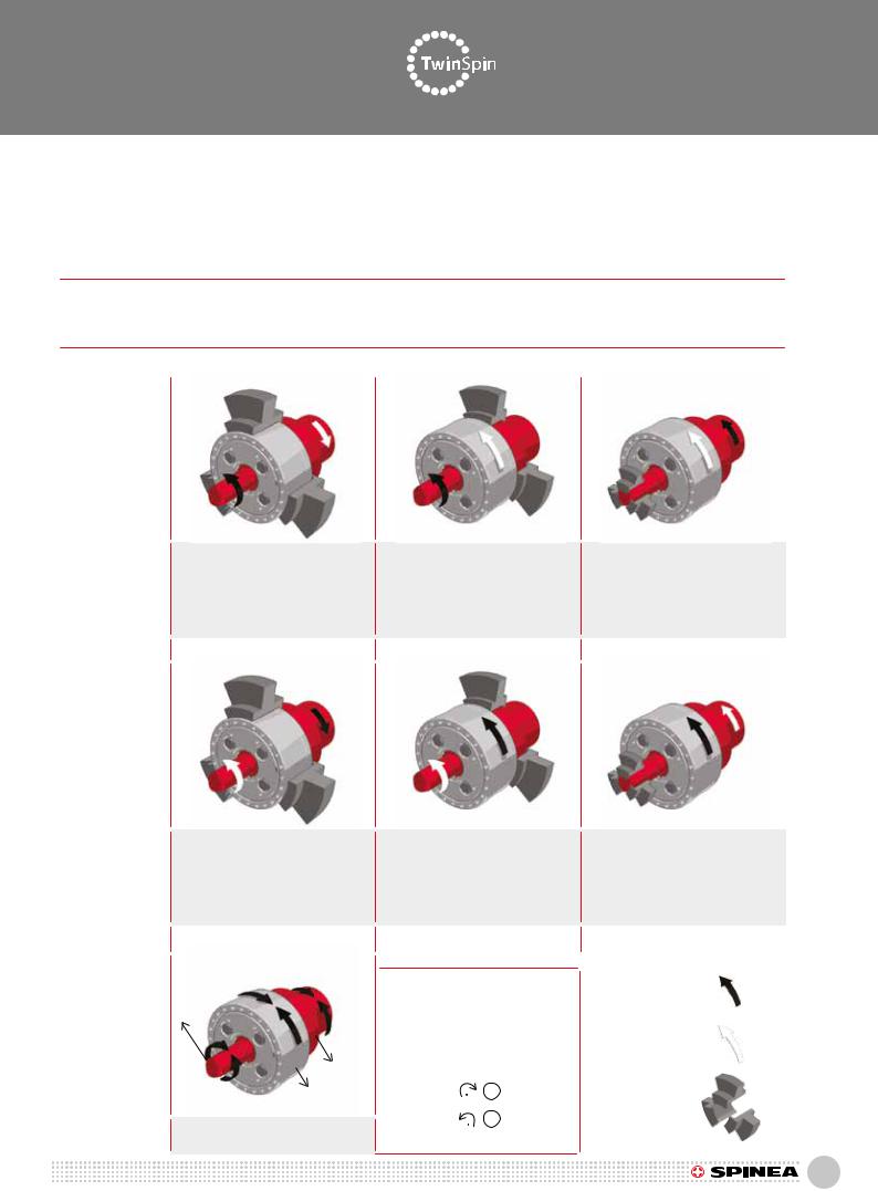
3.14T, E, H, M series rotation direction and reduction ratio
In the following equations, +i out represents input and output rotations in one direction, -i out represents input and output rotations in the opposite direction. The available reduction ratio “i” values are provided in the rating tables in Chapter 2.
3.14 Drehrichtung und Übersetzungsverhältnisse T, E, H, M Baureihe
In den nachfolgenden Gleichungen steht +i out für s Eingangsund Ausgangsdrehung in der gleichen Richtung, -i out steht für Eingangsund Ausgangsedrehung in entgegengesetzter Richtung. Die “i” Werte sind im Kapitel 2 angegeben.
iout= |
speed input |
iout= |
Eingangsdrehzahl |
|
speed output |
Ausgangsdrehzahl |
|||
|
|
Tab. 3.14: Rotation direction and reduction ratio / Drehrichtung und Übersetzung abhängig von Antriebsart
Speed
Reduction
Geschwindigkeits-
reduzierung
Speed
Acceleration
Geschwindigkeits-
erhöhung
Differential configuration
Differential
Konfiguration
Input / Antrieb: |
Input / Antrieb: |
Input / Antrieb: |
|||||||
Input shaft / Eingangswelle |
Input shaft / Eingangswelle |
Output flange / Abtriebflansch |
|||||||
Output / Abtrieb: |
Output / Abtrieb: |
Output / Abtrieb: |
|||||||
Output flange / Abtriebflan |
Case / Gehäuse |
Case / Gehäuse |
|||||||
Fixed / Fest: |
|
Fixed / Fest: |
|
Fixed / Fest: |
|||||
Case / Gehäuse |
|
Output flange / Abtriebflansch |
Input shaft / Eingangswelle |
||||||
i |
= - i |
i |
out |
= i +1 |
i |
out´ |
= |
i +1 |
|
|
|||||||||
out |
|
|
|
|
|
i |
|||
|
|
|
|
|
|
|
|
||
Input / Antrieb: |
|
|
Input / Antrieb: |
Input / Antrieb: |
|
|
|
|
||||||||||
Output flange / Abtriebflansch |
Case / Gehäuse |
|
|
|
|
Case / Gehäuse |
|
|
|
|
||||||||
Output / Abtrieb: |
Output / Abtrieb: |
Output / Abtrieb: |
||||||||||||||||
Input shaft / Eingangswelle |
Input shaft / Eingangswelle |
Output flange / Abtriebflansch |
||||||||||||||||
Fixed / Fest: |
|
|
Fixed / Fest: |
|
|
|
|
|
Fixed / Fest: |
|
|
|
|
|||||
Case / Gehäuse |
|
|
Output flange / Abtriebflansch |
Input shaft / Eingangswelle |
||||||||||||||
iout = |
|
-1 |
|
|
|
iout |
= |
|
1 |
|
|
iout = |
|
i |
|
|||
|
i |
|
|
|
i+1 |
|
i+1 |
|||||||||||
|
|
|
|
|
|
|
|
|
|
|||||||||
|
|
|
|
|
|
|
|
|
|
|
|
|
|
|||||
|
|
|
|
|
|
|
|
|
|
|
|
|
Input / Antrieb: |
|
|
|||
|
|
|
|
|
|
|
|
|
|
|
|
|
|
|
||||
nshaft |
|
|
|
|
1 |
|
= |
ncase - nflange |
|
|
|
|
|
|
|
|||
|
|
|
|
|
|
|
|
|
|
|||||||||
|
|
|
|
|
|
|
|
|
|
|
|
|||||||
|
|
|
|
|
|
i+1 |
nshaft- nflange |
|
Output / Abtrieb: |
|
|
|||||||
|
|
|
|
|
|
|
|
|
|
|
|
|
|
|
||||
|
|
|
nflange |
|
|
|
|
|
|
|
|
|
|
|
|
|
|
|
|
|
|
|
|
|
|
|
|
|
|
|
|
|
|
|
|
|
|
|
|
|
ncase |
|
|
|
|
|
+ |
|
|
Fixed / Fest: |
||||||
|
|
|
|
|
|
|
|
|
- |
|
|
|||||||
All three parts can rotate |
|
|
|
|
|
|
|
|
|
|
|
|
|
|||||
|
|
|
|
|
|
|
|
|
|
|
|
|
|
|
||||
Drei-Wellen-Getriebe |
|
|
|
|
|
|
|
|
|
|
|
|
|
|
|
|||
|
|
|
|
|
|
|
|
|
|
|
|
|
|
|
|
|
|
|
93

 S E L E C T I O N P R O C E D U R E / A U S W A H L V E R F A H R E N


Selection procedure / Auswahlverfahren
4. TWINSPIN SELECTION PROCEDURE
4.1 T, E, H, M series duty cycle
T1 |
maximum output torque at acceleration [Nm] |
|
T2 |
output torque at constant speed [Nm] |
|
T3 |
maximum output torque at deceleration [Nm] |
|
Tmax |
max. output torque at emergency stop [Nm] |
|
Tem |
allowable emergency torque |
|
t1 |
|
acceleration time [s] |
t2 |
|
constant motion time [s] |
t3 |
|
deceleration time [s] |
t4 |
|
idle time [s] |
t |
|
duty cycle time [s] |
nc max maximum continuous input speed [rpm] |
||
n1 |
average input speed at acceleration [rpm] |
|
n2 |
input speed at constant motion [rpm] |
|
n3 |
average input speed at deceleration [rpm] |
|
nmax |
maximum input speed [rpm] |
|
Fr |
radial output flange load [N] |
|
F , F |
, F , radial output flange load during acceleration, during |
|
r1 |
r2 |
r3 constant speed and during deceleration [N] |
Fa |
axial output flange load [N] |
|
a radial load effective arm Fr [m] |
||
b axial load effective arm Fa [m] |
||
i |
reduction ratio |
|
Outut torque
Input speed
In case the duty cycle is different from the one shown, please supply the drawing and values of your duty cycle. These values are important for us to be able to determine effectively lifetimes of TwinSpin reduction gears.
96

Selection procedure / Auswahlverfahren
4.2 T, E, H series selection flowchart
NO
NO
Fig. 4.2: Flowchart
97

Selection procedure / Auswahlverfahren
4.2 Flussdiagramm zur Getriebe Auswahl T, E, H Baureihe
NEIN
NEIN
Fig. 4.2: Flussdiagramm
98

Selection procedure / Auswahlverfahren
4.2.1 M series selection flowcharts
99

Selection procedure / Auswahlverfahren
4.2.1 Flussdiagramm zur Getriebe Auswahl M Baureihe
100

Selection procedure / Auswahlverfahren
4.3 T, E, H series selection example
• Input data - selection conditions
Acceleration torque Constant torque Braking torque Emergency torque
Average acceleration input speed Constant input speed Average breaking input speed Radial load Axial load
Radial force tilting arm Axial force tilting arm Max. allowable output flange deflection angle Acceleration time Constant speed time Braking time
•Calculation example
1.Calculation of average output torque (Ta )
4.3Auswahlbeispiel T, E, H Baureihe
•Eingabedaten - Auswahlbedingungen
T1=420 Nm T2=310 Nm T3=520 Nm
Tem=1500 Nm n1=1500 rpm
n2=3000 rpm n3=1500 rpm
Fr=1500 N Fa=1500 N a2=0.15m
b=0.2m
Θmax=3 arcmin. t1=0.3sec.
t2=0.5sec. t3=0.2sec.
Beschleunigungsmoment Konstantmoment Bremsmoment Not-Aus-Moment
Mittlere Beschleunigungsdrehzahl Drehzahl Konstantfahrt
Mittlere Bremsdrehzahl Radialkraft
Axialkraft Radialkraft-Hebelarm Axialkraft-Hebelarm
Max. zulässiger Abtriebsflansch-Ablenkwinkel Beschleunigungszeit
Zeit der Konstantgeschwindigkeit Bremszeit
• Berechnungsbeispiel
1. Berechnung des mittleren Abtriebsmoments (Ta )


 Nm
Nm
2. |
Calculation of average input speed (na ) |
2. |
Berechnung der mitteren Autriebsdrehzahl (na ) |
||
|
|
|
|
|
rpm |
|
|
|
|
|
|
3. |
Preliminary selection of a reduction gear from the rating table |
3. |
VorläufigeAuswahldesGetriebesausdentechn.Daten(Kapitel2): |
||
|
(Chapter 2): TS170141TC |
|
TS170141TC |
||
Technical specifications of the selected reduction gear:
Rated torque Rated input speed Maximum torque Emergency torque Effective input speed Maximum input speed Tilting stiffness
Maximum tilting moment (Fa=0) Maximum radial force Maximum axial force (Mc=0)
4. Service life calculation (Lh )
Spezifikation des ausgewählten Getriebes:
TR = 495 Nm
nR= 2 000 rpm Tmax = 1 238 Nm Tem = 2 475 Nm ne= 2 500 rpm f nmax = 4 000 rpm
Mt = 705 Nm/arcmin.
Mcmax = 2 430 Nm Fr max = 19 300 N Fa max = 27 900 N
Nennmoment
Nominale Antriebsdrehzahl
Maximales Moment
Not-Aus-Moment
Effektive Antriebsdrehzahl
Max. Antriebsdrehzahl
Kippsteifigkeit
Max. Kippmoment (Fa=0)
Max. Radialkraft
Max. Axialkraft (Mc=0)
4. Lebensdauerberechnung (Lh )
|
|
|
|
|
|
|
|
|
hrs |
|
|
|
|
|
|
|
|
||
5. |
Effective speed check (na , nef ) |
5. |
Kontrolle der effektiven Drehzahl (na, nef ) |
||||||
|
|
(na = 2 250 rpm) < (2 500 rpm = nef) ok |
|||||||
6. |
Input speed check (n2 , nmax ) |
6. |
Kontrolle der Antriebsdrehzahl (n2 , nmax ) |
||||||
|
|
(n2 = 3 000 rpm) < (nmax = 4 000 rpm) ok |
|||||||
101