

0445 / GWL_e_complete
.pdfStandard series KD 210
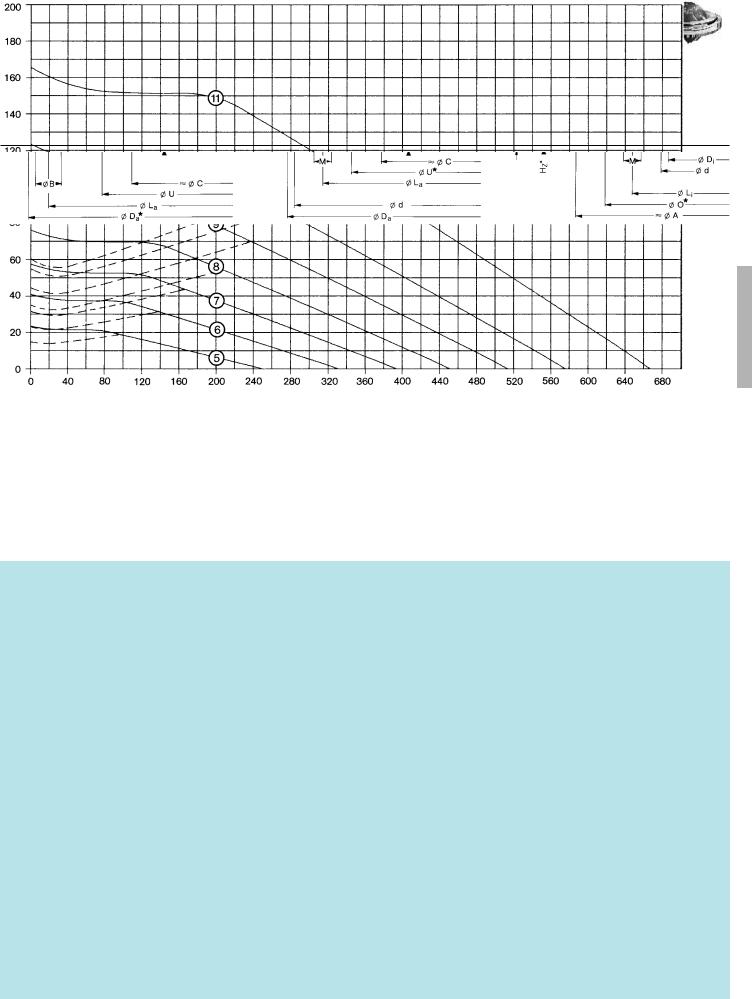
Standard bearing type 21, double number of bolt holes, profile ring
One bolt hole missing in the region of the filler plug
®
Rothe Erde Large-Diameter
Antifriction Bearings
n1 = 4 Conical grease nipple AM 8 x 1 DIN 71412
≈ equispaced
With ungeared bearings the grease nipples may be located on the inner ring, if requested.
= Filler plug
|
rolled |
√ |
––––– |
= √ |
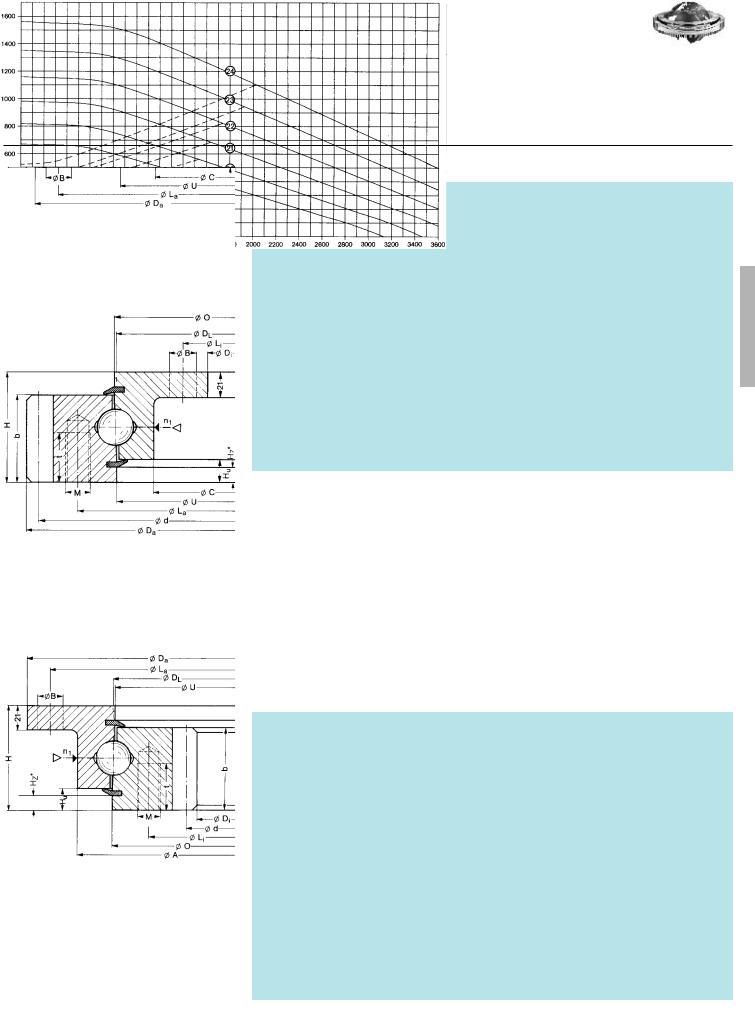
Static limiting load curves |
––––––– Raceway |
– – – Bolts |
–––––– Res. moment (kNm) ––––––
*If pilots are required on standard bearings, it is essential that this is indicated at the time of ordering.
Pilots can only be provided at nominal diameters marked with an *.
Pilot tolerances: |
|
|
Outside |
Inside |
|
Type 21/ |
520 ..... |
21/ |
650 |
–0.5 mm |
+0.5 mm |
Type 21/ |
750 ..... |
21/ |
950 |
–0.6 mm |
+0.6 mm |
Type 21/1050 ..... |
21/1200 |
–0.7 mm |
+0.7 mm |
||
Pilot height HZ* = 4.5 mm
Pilot height of companion structure = (HZ – 1) mm
–––––– Axial load (kN) ––––––
49

®
Standard series KD 210
Standard bearing type 21, precision bearing
Bearing ungeared
Rothe Erde Large-Diameter
Antifriction Bearings
Drawing No.
230.21.0475.013 Typ 21/520.0
230.21.0575.013 Typ 21/650.0
230.21.0675.013 Typ 21/750.0
230.21.0775.013 Typ 21/850.0
230.21.0875.013 Typ 21/950.0
230.21.0975.013 Typ 21/1050.0
230.21.1075.013 Typ 21/1200.0
|
|
|
|
|
|
|
Number of bolt holes |
|
Number of bolt holes |
|
|
|
|
|
|
|
Distance at bottom outer ring/inner ring |
Distance at top outer ring/inner ring |
|
|
|
|
Addendum reduction |
Permissible tangential forces normal |
Permissible tangential forces maximum |
|
1 |
|
|
Ball track diameter |
Weight |
Outer diameter (O.D.) |
Inner diameter (I.D.) |
Overall height |
External bolt circle diameter |
Internal bolt circle diameter |
External hole diameter |
Internal hole diameter |
Thread depth |
Number of grease nipples |
Diameter |
Diameter |
Diameter |
Diameter |
Gear P.C.D. |
Module |
Number of teeth |
Tooth width |
|
Bearing clearances |
Curves |
||||||||
DL |
|
Da |
Di |
H |
La |
Li |
na B/M |
ni |
B/M |
t |
n1 |
O |
U |
A |
C |
Hu |
Ho |
d |
m |
z |
b |
k · m |
|
|
axial u.radial |
|
|||
[mm] |
[kg] |
[mm] |
[mm] |
[mm] |
[mm] [mm] |
|
[mm] |
|
[mm] |
[mm] |
|
[mm] |
[mm] |
[mm] [mm] |
[mm] |
[mm] |
[mm] |
[mm] |
|
[mm] |
[mm] [kN] |
[kN] |
[mm] |
|
|||||
414 |
23,4 |
517 |
305 |
56 |
490 |
332 |
8 |
18 |
12 |
18 |
_ |
4 |
412,5 |
415,5 |
453 |
375 |
10,5 |
10,5 |
_ |
_ |
_ |
_ |
_ |
_ |
_ |
≥ 0 to 0,03 |
5 |
|
|
|
–0,11 |
+0,08 |
|
||||||||||||||||||||||||
|
|
|
|
|
|
|
|
|
|
|
|
|
|
|
|
|
|
|
|
|
|
|
|
|
|
|||
544 |
31,0 |
647 |
435 |
56 |
|
|
|
|
|
|
_ |
|
|
|
|
|
|
|
_ |
_ |
_ |
_ |
_ |
_ |
_ |
|
|
|
620 |
462 |
10 |
18 |
14 |
18 |
4 |
542,5 |
545,5 |
583 |
505 |
10,5 |
10,5 |
≥ 0 to 0,03 |
6 |
||||||||||||||
|
|
–0,13 |
+0,10 |
|
|
|
|
|
|
|
|
|
||||||||||||||||
|
|
|
|
|
|
|
|
|
|
|
|
|
|
|
|
|
|
|
|
|
|
|
|
|
|
|||
644 |
36,4 |
747 |
535 |
56 |
|
|
|
|
|
|
_ |
|
|
|
|
|
|
|
_ |
_ |
_ |
_ |
_ |
_ |
_ |
|
|
|
720 |
562 |
12 |
18 |
16 |
18 |
4 |
642,5 |
645,5 |
683 |
605 |
10,5 |
10,5 |
≥ 0 to 0,04 |
7 |
||||||||||||||
|
|
–0,13 |
+0,11 |
|
||||||||||||||||||||||||
|
|
|
|
|
|
|
|
|
|
|
|
|
|
|
|
|
|
|
|
|
|
|
|
|
|
|||
744 |
42,8 |
847 |
635 |
56 |
|
|
|
|
|
|
_ |
|
|
|
|
|
|
|
_ |
_ |
_ |
_ |
_ |
_ |
_ |
|
|
|
820 |
662 |
12 |
18 |
16 |
18 |
4 |
742,5 |
745,5 |
783 |
705 |
10,5 |
10,5 |
≥ 0 to 0,04 |
8 |
||||||||||||||
|
|
–0,14 |
+0,13 |
|
||||||||||||||||||||||||
|
|
|
|
|
|
|
|
|
|
|
|
|
|
|
|
|
|
|
|
|
|
|
|
|
|
|||
844 |
47,8 |
947 |
735 |
56 |
|
|
|
|
|
|
_ |
|
|
|
|
|
|
|
_ |
_ |
_ |
_ |
_ |
_ |
_ |
|
|
|
920 |
762 |
14 |
18 |
18 |
18 |
4 |
842,5 |
845,5 |
883 |
805 |
10,5 |
10,5 |
≥ 0 to 0,05 |
9 |
||||||||||||||
|
|
–0,14 |
+0,13 |
|
|
|
|
|
|
|
|
|
||||||||||||||||
|
|
|
|
|
|
|
|
|
|
|
|
|
|
|
|
|
|
|
|
|
|
|
|
|
|
|||
944 |
53,1 |
1047 |
835 |
56 |
|
|
|
|
|
|
_ |
|
|
|
|
|
|
|
_ |
_ |
_ |
_ |
_ |
_ |
_ |
|
|
|
1020 |
862 |
16 |
18 |
20 |
18 |
4 |
942,5 |
945,5 |
983 |
905 |
10,5 |
10,5 |
≥ 0 to 0,05 |
10 |
||||||||||||||
|
|
–0,17 |
+0,14 |
|
||||||||||||||||||||||||
|
|
|
|
|
|
|
|
|
|
|
|
|
|
|
|
|
|
|
|
|
|
|
|
|
|
|||
1094 |
61,9 |
1197 |
985 |
56 |
|
|
|
|
|
|
_ |
|
|
|
|
|
|
|
_ |
_ |
_ |
_ |
_ |
_ |
_ |
|
|
|
1170 |
1012 |
16 |
18 |
20 |
18 |
4 |
1092,5 |
1095,5 |
1133 |
1055 |
10,5 |
10,5 |
≥ 0 to 0,06 |
11 |
||||||||||||||
|
|
–0,17 |
+0,14 |
|
||||||||||||||||||||||||
|
|
|
|
|
|
|
|
|
|
|
|
|
|
|
|
|
|
|
|
|
|
|
|
|
|
|||
|
|
|
|
|
|
|
|
|
|
|
|
|
|
|
|
|
|
|
|
|
|
|
|
|
|
|
|
1 Axial clearance = tilting clearance
Bearings with external gear
231.21.0475.013 |
414 |
29,3 |
504,8 |
305 |
56 |
455 |
332 |
10 |
M 12 |
12 |
18 |
20 |
4 |
412,5 |
417 |
_ |
375 |
10,5 |
_ |
495 |
5 |
99 |
45,5 |
–0,5 |
11,75 |
23,50 |
≥ 0 to 0,03 |
|
||
5 |
||||||||||||||||||||||||||||||
Typ 21/520.1 |
|
|
|
+0,08 |
|
|
+0,10 |
|
|
|||||||||||||||||||||
|
|
|
|
|
|
|
|
|
|
|
|
|
|
|
|
|
|
|
|
|
|
|
|
|
|
|
||||
231.21.0575.013 |
544 |
39,5 |
640,8 |
435 |
56 |
585 |
462 |
14 |
M 12 |
14 |
18 |
20 |
4 |
542,5 |
547 |
_ |
505 |
10,5 |
_ |
630 |
6 |
105 |
45,5 |
–0,6 |
14,20 |
28,40 |
≥ 0 to 0,03 |
|
||
6 |
||||||||||||||||||||||||||||||
Typ 21/650.1 |
|
|
|
+0,10 |
|
|
+0,11 |
|
|
|||||||||||||||||||||
|
|
|
|
|
|
|
|
|
|
|
|
|
|
|
|
|
|
|
|
|
|
|
|
|
|
|
||||
231.21.0675.013 |
644 |
47,6 |
742,8 |
535 |
56 |
685 |
562 |
16 |
M 12 |
16 |
18 |
20 |
4 |
642,5 |
647 |
_ |
605 |
10,5 |
_ |
732 |
6 |
122 |
45,5 |
–0,6 |
14,20 |
28,40 |
≥ 0 to 0,04 |
|
||
7 |
||||||||||||||||||||||||||||||
Typ 21/750.1 |
|
|
|
+0,11 |
|
|
+0,13 |
|
|
|||||||||||||||||||||
|
|
|
|
|
|
|
|
|
|
|
|
|
|
|
|
|
|
|
|
|
|
|
|
|
|
|
||||
231.21.0775.013 |
744 |
53,5 |
838,8 |
635 |
56 |
785 |
662 |
18 |
M 12 |
16 |
18 |
20 |
4 |
742,5 |
747 |
_ |
705 |
10,5 |
_ |
828 |
6 |
138 |
45,5 |
–0,6 |
14,20 |
28,40 |
≥ 0 to 0,04 |
|
||
8 |
||||||||||||||||||||||||||||||
Typ 21/850.1 |
|
|
|
+0,13 |
|
|
+0,13 |
|
|
|||||||||||||||||||||
|
|
|
|
|
|
|
|
|
|
|
|
|
|
|
|
|
|
|
|
|
|
|
|
|
|
|
||||
231.21.0875.013 |
844 |
65,1 |
950,4 |
735 |
56 |
885 |
762 |
18 |
M 12 |
18 |
18 |
20 |
4 |
842,5 |
847 |
_ |
805 |
10,5 |
_ |
936 |
8 |
117 |
45,5 |
–0,8 |
18,93 |
37,86 |
≥ 0 to 0,05 |
|
||
9 |
||||||||||||||||||||||||||||||
Typ 21/950.1 |
|
|
|
+0,13 |
|
|
+0,14 |
|
|
|||||||||||||||||||||
|
|
|
|
|
|
|
|
|
|
|
|
|
|
|
|
|
|
|
|
|
|
|
|
|
|
|
||||
231.21.0975.013 |
944 |
69,6 |
1046,4 |
835 |
56 |
985 |
862 |
20 |
M 12 |
20 |
18 |
20 |
4 |
942,5 |
947 |
_ |
905 |
10,5 |
_ |
1032 |
8 |
129 |
45,5 |
–0,8 |
18,93 |
37,86 |
≥ 0 to 0,05 |
|
||
10 |
||||||||||||||||||||||||||||||
Typ 21/1050.1 |
|
|
|
+0,14 |
|
|
+0,14 |
|
|
|||||||||||||||||||||
|
|
|
|
|
|
|
|
|
|
|
|
|
|
|
|
|
|
|
|
|
|
|
|
|
|
|
||||
231.21.1075.013 |
1094 |
83,0 |
1198,4 |
985 |
56 |
1135 |
1012 |
22 |
M 12 |
20 |
18 |
20 |
4 |
1092,5 |
1097 |
_ |
1055 |
10,5 |
_ |
1184 |
8 |
148 |
45,5 |
–0,8 |
18,93 |
37,86 |
≥ 0 to 0,06 |
|
||
11 |
||||||||||||||||||||||||||||||
Typ 21/1200.1 |
|
|
|
+0,14 |
|
|
+0,17 |
|
|
|||||||||||||||||||||
|
|
|
|
|
|
|
|
|
|
|
|
|
|
|
|
|
|
|
|
|
|
|
|
|
|
|
||||
|
|
|
|
|
|
|
|
|
|
|
|
|
|
|
|
|
|
|
|
|
||||||||||
|
|
|
|
|
|
|
|
|
|
|
|
|
|
|
|
|
|
|||||||||||||
|
|
|
New ø Da off 1991 addendum reduction 0,1 · m |
|
|
|
|
|
|
|
|
|
|
|
|
1 |
Axial clearance = tilting clearance |
|
||||||||||||
Bearings with internal gear
232.21.0475.013 |
414 |
27,1 |
517 |
326,5 |
56 |
490 |
375 |
8 |
18 |
12 |
M 12 |
20 |
4 |
411 |
415,5 |
453 |
_ |
10,5 |
_ |
335 |
5 |
67 |
45,5 |
–0,75 |
13,54 |
27,08 |
≥ 0 to 0,03 |
|
|
5 |
|||||||||||||||||||||||||||||
Typ 21/520.2 |
|
|
–0,11 |
|
|
–0,10 |
|
|
|
||||||||||||||||||||
|
|
|
|
|
|
|
|
|
|
|
|
|
|
|
|
|
|
|
|
|
|
|
|
|
|
||||
232.21.0575.013 |
544 |
36,9 |
647 |
445,2 |
56 |
620 |
505 |
10 |
18 |
16 |
M 12 |
20 |
4 |
541 |
545,5 |
583 |
_ |
10,5 |
_ |
456 |
6 |
76 |
45,5 |
–0,60 |
16,00 |
32,00 |
≥ 0 to 0,03 |
|
|
6 |
|||||||||||||||||||||||||||||
Typ 21/650.2 |
|
|
–0,13 |
|
|
–0,11 |
|
|
|
||||||||||||||||||||
|
|
|
|
|
|
|
|
|
|
|
|
|
|
|
|
|
|
|
|
|
|
|
|
|
|
||||
232.21.0675.013 |
644 |
43,7 |
747 |
547,2 |
56 |
720 |
605 |
12 |
18 |
18 |
M 12 |
20 |
4 |
641 |
645,5 |
683 |
_ |
10,5 |
_ |
558 |
6 |
93 |
45,5 |
–0,60 |
15,62 |
31,24 |
≥ 0 to 0,04 |
|
|
7 |
|||||||||||||||||||||||||||||
Typ 21/750.2 |
|
|
–0,13 |
|
|
–0,13 |
|
|
|
||||||||||||||||||||
|
|
|
|
|
|
|
|
|
|
|
|
|
|
|
|
|
|
|
|
|
|
|
|
|
|
||||
232.21.0775.013 |
744 |
51,1 |
847 |
649,2 |
56 |
820 |
705 |
12 |
18 |
20 |
M 12 |
20 |
4 |
741 |
745,5 |
783 |
_ |
10,5 |
_ |
660 |
6 |
110 |
45,5 |
–0,60 |
15,32 |
30,64 |
≥ 0 to 0,04 |
|
|
8 |
|||||||||||||||||||||||||||||
Typ 21/850.2 |
|
|
–0,14 |
|
|
–0,13 |
|
|
|
||||||||||||||||||||
|
|
|
|
|
|
|
|
|
|
|
|
|
|
|
|
|
|
|
|
|
|
|
|
|
|
||||
232.21.0875.013 |
844 |
61,6 |
947 |
737,6 |
56 |
920 |
805 |
14 |
18 |
20 |
M 12 |
20 |
4 |
841 |
845,5 |
883 |
_ |
10,5 |
_ |
752 |
8 |
94 |
45,5 |
–0,80 |
20,80 |
41,60 |
≥ 0 to 0,05 |
|
|
9 |
|||||||||||||||||||||||||||||
Typ 21/950.2 |
|
|
–0,14 |
|
|
–0,14 |
|
|
|
||||||||||||||||||||
|
|
|
|
|
|
|
|
|
|
|
|
|
|
|
|
|
|
|
|
|
|
|
|
|
|
||||
232.21.0975.013 |
944 |
65,8 |
1047 |
841,6 |
56 |
1020 |
905 |
16 |
18 |
22 |
M 12 |
20 |
4 |
941 |
945,5 |
983 |
_ |
10,5 |
_ |
856 |
8 |
107 |
45,5 |
–0,80 |
20,49 |
40,98 |
≥ 0 to 0,05 |
|
|
10 |
|||||||||||||||||||||||||||||
Typ 21/1050.2 |
|
|
–0,17 |
|
|
–0,14 |
|
|
|
||||||||||||||||||||
|
|
|
|
|
|
|
|
|
|
|
|
|
|
|
|
|
|
|
|
|
|
|
|
|
|
||||
232.21.1075.013 |
1094 |
80,7 |
1197 |
985,6 |
56 |
1170 |
1055 |
16 |
18 |
24 |
M 12 |
20 |
4 |
1091 |
1095,5 |
1133 |
_ |
10,5 |
_ |
1000 |
8 |
125 |
45,5 |
–0,80 |
20,16 |
40,32 |
≥ 0 to 0,06 |
|
|
11 |
|||||||||||||||||||||||||||||
Typ 21/1200.2 |
|
|
–0,17 |
|
|
–0,17 |
|
|
|
||||||||||||||||||||
|
|
|
|
|
|
|
|
|
|
|
|
|
|
|
|
|
|
|
|
|
|
|
|
|
|
|
|
|
1 Axial clearance = tilting clearance
50
Standard series KD 210
Standard bearing type 21, precision bearing
®
Rothe Erde Large-Diameter
Antifriction Bearings
n1 = 4 Conical grease nipple AM 8 x 1 DIN 71412
≈ equispaced
With ungeared bearings the grease nipples may be located on the inner ring, if requested.
= Filler plug
|
rolled |
√ |
––––– |
= √ |
Pilot height HZ* = 4.5 mm
Pilot height of companion structure = (HZ – 1) mm
Static limiting load curves |
––––––– Raceway |
– – – Bolts |
For loads exceeding the limiting load curves for the bolts, the number of fastening bolts must the doubled.
–––––– Res. moment (kNm) ––––––
–––––– Axial load (kN) ––––––
51
®
Standard series KD 210
Standard bearings type 110, standard bearing
Bearing ungeared
Rothe Erde Large-Diameter
Antifriction Bearings
Drawing No.
280.30.0900.013 Typ 110/1100.0
280.30.1000.013 Typ 110/1200.0
280.30.1100.013 Typ 110/1300.0
280.30.1200.013 Typ 110/1400.0
280.30.1300.013 Typ 110/1500.0
280.30.1400.013 Typ 110/1600.0
|
|
|
|
|
|
|
|
Number of bolt holes |
|
Number of bolt holes |
|
|
|
|
|
|
|
Distance at bottom outer ring/inner ring |
Distance at top outer ring/inner ring |
|
|
|
|
Addendum reduction |
Permissible tangential forces normal |
Permissible tangential forces maximum |
|
1 |
|
|
|
Ball track diameter |
|
Weight |
Outer diameter (O.D.) |
Inner diameter (I.D.) |
Overall height |
External bolt circle diameter |
Internal bolt circle diameter |
External hole diameter |
Internal hole diameter |
Thread depth |
Number of grease nipples |
Diameter |
Diameter |
Diameter |
Diameter |
Gear P.C.D. |
Module |
Number of teeth |
Tooth width |
|
Bearing clearances |
|
Curves |
||||||||
|
|
|
|||||||||||||||||||||||||||||
|
|
|
|
|
|
|
|
|
|
|
|
|
|
|
|
|
|
|
|
|
|
|
|
|
|
|
|
|
|
||
DL |
|
|
Da |
Di |
H |
La |
Li |
na |
B/M |
ni |
B/M |
t |
n1 |
O |
U |
A |
C |
Hu |
Ho |
d |
m |
z |
b |
k · m |
|
|
axial |
|
radial |
|
|
[mm] |
|
[kg] |
[mm] |
[mm] |
[mm] |
[mm] [mm] |
|
[mm] |
|
[mm] |
[mm] |
|
[mm] |
[mm] |
[mm] [mm] |
[mm] |
[mm] |
[mm] |
[mm] |
|
[mm] |
[mm] |
[kN] |
[kN] |
[mm] |
|
[mm] |
|
|||
|
|
|
|
|
|
|
|
|
|
|
|
_ |
|
|
|
|
|
|
|
_ |
_ |
_ |
_ |
_ |
_ |
_ |
|
|
|
|
|
955 |
|
131 |
1100 |
805 |
90 |
1060 |
845 |
30 |
22 |
30 |
22 |
6 |
956,5 |
953,5 |
1017 |
893 |
19 |
19 |
≤ 0,40 |
|
≤ 0,31 |
19 |
|||||||||
|
|
|
|
|
|
|
|
|
|
|
|
_ |
|
|
|
|
|
|
|
_ |
_ |
_ |
_ |
_ |
_ |
_ |
|
|
|
|
|
|
|
|
|
|
|
|
|
|
|
|
|
|
|
|
|
|
|
|
|
|
|
|
|||||||||
1055 |
|
145 |
1200 |
905 |
90 |
1160 |
945 |
30 |
22 |
30 |
22 |
6 |
1056,5 |
1053,5 |
1117 |
993 |
19 |
19 |
≤ 0,40 |
|
≤ 0,31 |
20 |
|||||||||
|
|
|
|
|
|
|
|
|
|
|
|
_ |
|
|
|
|
|
|
|
_ |
_ |
_ |
_ |
_ |
_ |
_ |
|
|
|
|
|
|
|
|
|
|
|
|
|
|
|
|
|
|
|
|
|
|
|
|
|
|
|
|
|||||||||
1155 |
|
159 |
1300 |
1005 |
90 |
1260 |
1045 |
36 |
22 |
36 |
22 |
6 |
1156,5 |
1153,5 |
1217 |
1093 |
19 |
19 |
≤ 0,40 |
|
≤ 0,31 |
21 |
|||||||||
|
|
|
|
|
|
|
|
|
|
|
|
_ |
|
|
|
|
|
|
|
_ |
_ |
_ |
_ |
_ |
_ |
_ |
|
|
|
|
|
|
|
|
|
|
|
|
|
|
|
|
|
|
|
|
|
|
|
|
|
|
|
|
|||||||||
1255 |
|
172 |
1400 |
1105 |
90 |
1360 |
1145 |
42 |
22 |
42 |
22 |
6 |
1256,5 |
1253,5 |
1317 |
1193 |
19 |
19 |
≤ 0,45 |
|
≤ 0,37 |
22 |
|||||||||
|
|
|
|
|
|
|
|
|
|
|
|
_ |
|
|
|
|
|
|
|
_ |
_ |
_ |
_ |
_ |
_ |
_ |
|
|
|
|
|
|
|
|
|
|
|
|
|
|
|
|
|
|
|
|
|
|
|
|
|
|
|
|
|||||||||
1355 |
|
186 |
1500 |
1205 |
90 |
1460 |
1245 |
42 |
22 |
42 |
22 |
6 |
1356,5 |
1353,5 |
1417 |
1293 |
19 |
19 |
≤ 0,45 |
|
≤ 0,37 |
23 |
|||||||||
|
|
|
|
|
|
|
|
|
|
|
|
_ |
|
|
|
|
|
|
|
_ |
_ |
_ |
_ |
_ |
_ |
_ |
|
|
|
|
|
|
|
|
|
|
|
|
|
|
|
|
|
|
|
|
|
|
|
|
|
|
|
|
|||||||||
1455 |
|
200 |
1600 |
1305 |
90 |
1560 |
1345 |
48 |
22 |
48 |
22 |
6 |
1456,5 |
1453,5 |
1517 |
1393 |
19 |
19 |
≤ 0,45 |
|
≤ 0,37 |
24 |
|||||||||
|
|
|
|
|
|
|
|
|
|
|
|
|
|
|
|
|
|
|
|
|
|
|
|
|
|
|
|
|
|
|
|
|
|
|
|
|
|
|
|
|
|
|
|
|
|
|
|
|
|
|
|
|
|
|
|
|
|
|
|
|
|
|
|
1 Axial clearance = tilting clearance
Bearings with external gear
281.30.0900.013 |
955 |
165 1096,2 |
805 |
90 |
1016 |
845 |
30 |
M 20 |
30 |
22 |
40 |
6 |
956,5 |
953,5 |
_ |
893 |
19 |
_ |
1080 |
9 |
120 |
71 |
–0,9 |
33,23 66,46 |
≤ 0,40 |
≤ 0,31 |
|
|
19 |
||||||||||||||||||||||||||||
Typ 110/1100.1 |
|
|
||||||||||||||||||||||||||
281.30.1000.013 |
1055 |
183 1198,2 |
905 |
90 |
1116 |
945 |
30 |
M 20 |
30 |
22 |
40 |
6 |
1056,5 |
1053,5 |
_ |
993 |
19 |
_ |
1180 |
10 |
118 |
71 |
–1,5 |
36,92 73,84 |
≤ 0,40 |
≤ 0,31 |
|
|
20 |
||||||||||||||||||||||||||||
Typ 110/1200.1 |
|
|
||||||||||||||||||||||||||
281.30.1100.013 |
1155 |
200 1298,2 1005 |
90 |
1216 |
1045 |
36 |
M 20 |
36 |
22 |
40 |
6 |
1156,5 |
1153,5 |
_ |
1093 |
19 |
_ |
1280 |
10 |
128 |
71 |
–1,6 |
36,92 73,84 |
≤ 0,40 |
≤ 0,31 |
|
||
21 |
||||||||||||||||||||||||||||
Typ 110/1300.1 |
|
|
||||||||||||||||||||||||||
281.30.1200.013 |
1255 |
216 1398,2 1105 |
90 |
1316 |
1145 |
42 |
M 20 |
42 |
22 |
40 |
6 |
1256,5 |
1253,5 |
_ |
1193 |
19 |
_ |
1380 |
10 |
138 |
71 |
–1,6 |
36,92 73,84 |
≤ 0,45 |
≤ 0,37 |
|
||
22 |
||||||||||||||||||||||||||||
Typ 110/1400.1 |
|
|
||||||||||||||||||||||||||
281.30.1300.013 |
1355 |
234 1498,2 1205 |
90 |
1416 |
1245 |
42 |
M 20 |
42 |
22 |
40 |
6 |
1356,5 |
1353,5 |
_ |
1293 |
19 |
_ |
1480 |
10 |
148 |
71 |
–1,8 |
36,92 73,84 |
≤ 0,45 |
≤ 0,37 |
|
||
23 |
||||||||||||||||||||||||||||
Typ 110/1500.1 |
|
|
||||||||||||||||||||||||||
281.30.1400.013 |
1455 |
250 1598,2 1305 |
90 |
1516 |
1345 |
48 |
M 20 |
48 |
22 |
40 |
6 |
1456,5 |
1453,5 |
_ |
1393 |
19 |
_ |
1580 |
10 |
158 |
71 |
–1,8 |
36,92 73,84 |
≤ 0,45 |
≤ 0,37 |
|
||
24 |
||||||||||||||||||||||||||||
Typ 110/1600.1 |
|
|
||||||||||||||||||||||||||
|
|
|
|
|
|
|
|
|
|
|
|
|
|
|
|
|
|
|
|
|||||||||
|
|
New ø Da off 1991 addendum reduction 0,1 · m |
|
|
|
|
|
|
|
|
|
|
|
|
|
|||||||||||||
|
|
|
|
|
|
|
|
|
|
|
|
|
1 |
Axial clearance = tilting clearance |
|
|||||||||||||
|
|
|
|
|
|
|
|
|
|
|
|
|
|
|
|
|
|
|
|
|
|
|
|
|
|
|
|
|
Bearings with internal gear
282.30.0900.013 |
955 |
159 |
1100 |
812 |
90 |
1060 |
894 |
30 |
22 |
30 |
M 20 |
40 |
6 |
956,5 |
953,5 |
1017 |
_ |
19 |
_ |
830 |
10 |
83 |
71 |
–1 |
41,18 |
82,36 |
≤ 0,40 |
≤ 0,31 |
|
|
19 |
||||||||||||||||||||||||||||||
Typ 110/1100.2 |
|
|
||||||||||||||||||||||||||||
282.30.1000.013 |
1055 |
176 |
1200 |
912 |
90 |
1160 |
994 |
30 |
22 |
30 |
M 20 |
40 |
6 |
1056,5 |
1053,5 |
1117 |
_ |
19 |
_ |
930 |
10 |
93 |
71 |
–1 |
40,63 |
81,26 |
≤ 0,40 |
≤ 0,31 |
|
|
20 |
||||||||||||||||||||||||||||||
Typ 110/1200.2 |
|
|
||||||||||||||||||||||||||||
282.30.1100.013 |
1155 |
192 |
1300 |
1012 |
90 |
1260 |
1094 |
36 |
22 |
36 |
M 20 |
40 |
6 |
1156,5 |
1153,5 |
1217 |
_ |
19 |
_ |
1030 |
10 |
103 |
71 |
–1 |
40,15 |
80,30 |
≤ 0,40 |
≤ 0,31 |
|
|
21 |
||||||||||||||||||||||||||||||
Typ 110/1300.2 |
|
|
||||||||||||||||||||||||||||
282.30.1200.013 |
1255 |
208 |
1400 |
1112 |
90 |
1360 |
1194 |
42 |
22 |
42 |
M 20 |
40 |
6 |
1256,5 |
1253,5 |
1317 |
_ |
19 |
_ |
1130 |
10 |
113 |
71 |
–1 |
39,74 |
79,46 |
≤ 0,45 |
≤ 0,37 |
|
|
22 |
||||||||||||||||||||||||||||||
Typ 110/1400.2 |
|
|
||||||||||||||||||||||||||||
282.30.1300.013 |
1355 |
226 |
1500 |
1212 |
90 |
1460 |
1294 |
42 |
22 |
42 |
M 20 |
40 |
6 |
1356,5 |
1353,5 |
1417 |
_ |
19 |
_ |
1230 |
10 |
123 |
71 |
–1 |
39,39 |
78,78 |
≤ 0,45 |
≤ 0,37 |
|
|
23 |
||||||||||||||||||||||||||||||
Typ 110/1500.2 |
|
|
||||||||||||||||||||||||||||
282.30.1400.013 |
1455 |
243 |
1600 |
1310 |
90 |
1560 |
1394 |
48 |
22 |
48 |
M 20 |
40 |
6 |
1456,5 |
1453,5 |
1517 |
_ |
19 |
_ |
1330 |
10 |
133 |
71 |
–1 |
39,10 |
78,20 |
≤ 0,45 |
≤ 0,37 |
|
|
24 |
||||||||||||||||||||||||||||||
Typ 110/1600.2 |
|
|
1 Axial clearance = tilting clearance
52
Standard series KD 210
Standard bearings type 110, standard bearing
®
Rothe Erde Large-Diameter
Antifriction Bearings
*If pilots are required on standard bearings, it is essential that this is indicated at the time of ordering.
Pilots can only be provided at nominal diameters marked with an *.
Pilot tolerances: |
|
Outside |
Inside |
Type 110/1100 ..... |
110/1300 |
–0.25 mm |
+0.25 mm |
Type 110/1400 ..... |
110/1600 |
–0.30 mm |
+0.30 mm |
Pilot height HZ = 13 mm
Pilot height of companion structure = (HZ – 1) mm
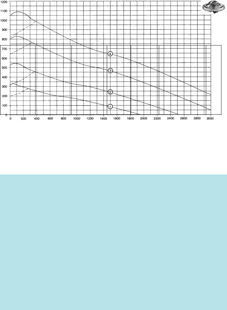
Static limiting load curves |
––––––– Raceway |
– – – Bolts |
–––––– Res. moment (kNm) ––––––
–––––– Axial load (kN) ––––––
n1 |
= Conical grease nipple |
Raceway reference loads or static limiting load curves and |
|
AM 8 x 1 DIN 71412 |
service life curves must be determined using th load factors |
|
≈ equispaced |
shown in the Table 1 on Page 11. |
|
With ungeared bearings |
|
|
the grease nipples may be |
|
|
located on the inner ring, |
|
|
if requested. |
|
|
= Filler plug |
|
Service life curves · 30,000 revolutions
–––––– Res. moment (kNm) ––––––
–––––– Axial load (kN) ––––––
53
®
Standard series KD 210
Standard bearing type 110, precision bearing
Bearing ungeared
Rothe Erde Large-Diameter
Antifriction Bearings
Drawing No.
280.30.0975.013 Typ 110/1100.0
280.30.1075.013 Typ 110/1200.0
280.30.1175.013 Typ 110/1300.0
280.30.1275.013 Typ 110/1400.0
280.30.1375.013 Typ 110/1500.0
280.30.1475.013 Typ 110/1600.0
|
|
|
|
|
|
|
Number of bolt holes |
|
Number of bolt holes |
|
|
|
|
|
|
|
Distance at bottom outer ring/inner ring |
Distance at top outer ring/inner ring |
|
|
|
|
Addendum reduction |
Permissible tangential forces normal |
Permissible tangential forces maximum |
|
1 |
|
|
Ball track diameter |
Weight |
Outer diameter (O.D.) |
Inner diameter (I.D.) |
Overall height |
External bolt circle diameter |
Internal bolt circle diameter |
External hole diameter |
Internal hole diameter |
Thread depth |
Number of grease nipples |
Diameter |
Diameter |
Diameter |
Diameter |
Gear P.C.D. |
Module |
Number of teeth |
Tooth width |
|
Bearing clearances |
Curves |
||||||||
DL |
|
Da |
Di |
H |
La |
Li |
na B/M |
ni |
B/M |
t |
n1 |
O |
U |
A |
C |
Hu |
Ho |
d |
m |
z |
b |
k · m |
|
|
axial u.radial |
|
|||
[mm] |
[kg] |
[mm] |
[mm] |
[mm] |
[mm] [mm] |
|
[mm] |
|
[mm] |
[mm] |
|
[mm] |
[mm] |
[mm] [mm] |
[mm] |
[mm] |
[mm] |
[mm] |
|
[mm] |
[mm] [kN] |
[kN] |
[mm] |
|
|||||
955 |
131 |
1098 |
807 |
90 |
1060 |
845 |
30 |
22 |
30 |
22 |
_ |
6 |
956,5 |
953,5 |
1017 |
893 |
19 |
19 |
_ |
_ |
_ |
_ |
_ |
_ |
_ |
≥ 0 bis 0,06 |
19 |
|
|
|
–0,17 |
+0,14 |
|
|
|
|
|
|
|
|
|
||||||||||||||||
|
|
|
|
|
|
|
|
|
|
|
|
|
|
|
|
|
|
|
|
|
|
|
|
|
|
|||
1055 |
145 |
1198 |
907 |
90 |
|
|
|
|
|
|
_ |
|
|
|
|
|
|
|
_ |
_ |
_ |
_ |
_ |
_ |
_ |
|
|
|
1160 |
945 |
30 |
22 |
30 |
22 |
6 |
1056,5 |
1053,5 |
1117 |
993 |
19 |
19 |
≥ 0 bis 0,06 |
20 |
||||||||||||||
|
|
–0,17 |
+0,14 |
|
|
|
|
|
|
|
|
|
||||||||||||||||
|
|
|
|
|
|
|
|
|
|
|
|
|
|
|
|
|
|
|
|
|
|
|
|
|
|
|||
1155 |
159 |
1298 |
1007 |
90 |
|
|
|
|
|
|
_ |
|
|
|
|
|
|
|
_ |
_ |
_ |
_ |
_ |
_ |
_ |
|
|
|
1260 |
1045 |
36 |
22 |
36 |
22 |
6 |
1156,5 |
1153,5 |
1217 |
1093 |
19 |
19 |
≥ 0 bis 0,06 |
21 |
||||||||||||||
|
|
–0,20 |
+0,17 |
|
|
|
|
|
|
|
|
|
||||||||||||||||
|
|
|
|
|
|
|
|
|
|
|
|
|
|
|
|
|
|
|
|
|
|
|
|
|
|
|||
1255 |
172 |
1398 |
1107 |
90 |
|
|
|
|
|
|
_ |
|
|
|
|
|
|
|
_ |
_ |
_ |
_ |
_ |
_ |
_ |
|
|
|
1360 |
1145 |
42 |
22 |
42 |
22 |
6 |
1256,5 |
1253,5 |
1317 |
1193 |
19 |
19 |
≥ 0 bis 0,07 |
22 |
||||||||||||||
|
|
–0,20 |
+0,17 |
|
|
|
|
|
|
|
|
|
||||||||||||||||
|
|
|
|
|
|
|
|
|
|
|
|
|
|
|
|
|
|
|
|
|
|
|
|
|
|
|||
1355 |
186 |
1498 |
1207 |
90 |
|
|
|
|
|
|
_ |
|
|
|
|
|
|
|
_ |
_ |
_ |
_ |
_ |
_ |
_ |
|
|
|
1460 |
1245 |
42 |
22 |
42 |
22 |
6 |
1356,5 |
1353,5 |
1417 |
1293 |
19 |
19 |
≥ 0 bis 0,07 |
23 |
||||||||||||||
|
|
–0,20 |
+0,17 |
|
|
|
|
|
|
|
|
|
||||||||||||||||
|
|
|
|
|
|
|
|
|
|
|
|
|
|
|
|
|
|
|
|
|
|
|
|
|
|
|||
1455 |
200 |
1598 |
1307 |
90 |
|
|
|
|
|
|
_ |
|
|
|
|
|
|
|
_ |
_ |
_ |
_ |
_ |
_ |
_ |
|
|
|
1560 |
1345 |
48 |
22 |
48 |
22 |
6 |
1456,5 |
1453,5 |
1517 |
1393 |
19 |
19 |
≥ 0 bis 0,07 |
24 |
||||||||||||||
|
|
–0,20 |
+0,20 |
|
|
|
|
|
|
|
|
|
||||||||||||||||
|
|
|
|
|
|
|
|
|
|
|
|
|
|
|
|
|
|
|
|
|
|
|
|
|
|
|
|
1 Axial clearance = tilting clearance
Bearings with external gear
281.30.0975.013 |
955 |
165 |
1096,2 |
807 |
90 |
1016 |
845 |
30 |
M 20 |
30 |
22 |
40 |
6 |
956,5 |
955 |
_ |
893 |
19 |
_ |
1080 |
9 |
120 |
71 |
–0,9 |
33,23 |
66,46 |
≥ 0 bis 0,06 |
|
|
19 |
|||||||||||||||||||||||||||||
Typ 110/1100.1 |
|
|
|
+0,14 |
|
|
+0,14 |
|
|
||||||||||||||||||||
281.30.1075.013 |
1055 |
183 |
1198,2 |
907 |
90 |
1116 |
945 |
30 |
M 20 |
30 |
22 |
40 |
6 |
1056,5 |
1055 |
_ |
993 |
19 |
_ |
1180 |
10 |
118 |
71 |
–1,5 |
36,92 |
73,84 |
≥ 0 bis 0,06 |
|
|
20 |
|||||||||||||||||||||||||||||
Typ 110/1200.1 |
|
|
|
+0,14 |
|
|
+0,17 |
|
|
||||||||||||||||||||
281.30.1175.013 |
1155 |
200 |
1298,2 1007 |
90 |
1216 |
1045 |
36 |
M 20 |
36 |
22 |
40 |
6 |
1156,5 |
1155 |
_ |
1093 |
19 |
_ |
1280 |
10 |
128 |
71 |
–1,6 |
36,92 |
73,84 |
≥ 0 bis 0,06 |
|
||
21 |
|||||||||||||||||||||||||||||
Typ 110/1300.1 |
|
|
|
+0,17 |
|
|
+0,17 |
|
|
||||||||||||||||||||
281.30.1275.013 |
1255 |
216 |
1398,2 1107 |
90 |
1316 |
1145 |
42 |
M 20 |
42 |
22 |
40 |
6 |
1256,5 |
1255 |
_ |
1193 |
19 |
_ |
1380 |
10 |
138 |
71 |
–1,6 |
36,92 |
73,84 |
≥ 0 bis 0,07 |
|
||
22 |
|||||||||||||||||||||||||||||
Typ 110/1400.1 |
|
|
|
+0,17 |
|
|
+0,20 |
|
|
||||||||||||||||||||
281.30.1375.013 |
1355 |
234 |
1498,2 1207 |
90 |
1416 |
1245 |
42 |
M 20 |
42 |
22 |
40 |
6 |
1356,5 |
1355 |
_ |
1293 |
19 |
_ |
1480 |
10 |
148 |
71 |
–1,8 |
36,92 |
73,84 |
≥ 0 bis 0,07 |
|
||
23 |
|||||||||||||||||||||||||||||
Typ 110/1500.1 |
|
|
|
+0,17 |
|
|
+0,20 |
|
|
||||||||||||||||||||
281.30.1475.013 |
1455 |
250 |
1598,2 1307 |
90 |
1516 |
1345 |
48 |
M 20 |
48 |
22 |
40 |
6 |
1456,5 |
1455 |
_ |
1393 |
19 |
_ |
1580 |
10 |
158 |
71 |
–1,8 |
36,92 |
73,84 |
≥ 0 bis 0,07 |
|
||
24 |
|||||||||||||||||||||||||||||
Typ 110/1600.1 |
|
|
|
+0,20 |
|
|
+0,20 |
|
|
||||||||||||||||||||
|
|
|
|
|
|
|
|
|
|
|
|
|
|
|
|
|
|
|
|
||||||||||
|
|
|
New ø Da off 1991 addendum reduction 0,1 · m |
|
|
|
|
|
|
|
|
|
|
|
|
|
|||||||||||||
|
|
|
|
|
|
|
|
|
|
|
|
|
|
1 |
Axial clearance = tilting clearance |
|
|||||||||||||
|
|
|
|
|
|
|
|
|
|
|
|
|
|
|
|
|
|
|
|
|
|
|
|
|
|
|
|
|
|
Bearings with internal gear
282.30.0975.013 |
955 |
159 |
1098 |
812 |
90 |
1060 |
894 |
30 |
22 |
30 |
M 20 |
40 |
6 |
955 |
953,5 |
1017 |
_ |
19 |
_ |
830 |
10 |
83 |
71 |
–1 |
41,18 |
82,36 |
≥ 0 bis 0,06 |
|
|
19 |
|||||||||||||||||||||||||||||
Typ 110/1100.2 |
|
|
–0,17 |
|
|
–0,14 |
|
|
|
||||||||||||||||||||
282.30.1075.013 |
1055 |
176 |
1198 |
912 |
90 |
1160 |
994 |
30 |
22 |
30 |
M 20 |
40 |
6 |
1055 |
1053,5 |
1117 |
_ |
19 |
_ |
930 |
10 |
93 |
71 |
–1 |
40,63 |
81,26 |
≥ 0 bis 0,06 |
|
|
20 |
|||||||||||||||||||||||||||||
Typ 110/1200.2 |
|
|
–0,17 |
|
|
–0,17 |
|
|
|
||||||||||||||||||||
282.30.1175.013 |
1155 |
192 |
1298 |
1012 |
90 |
1260 |
1094 |
36 |
22 |
36 |
M 20 |
40 |
6 |
1155 |
1153,5 |
1217 |
_ |
19 |
_ |
1030 |
10 |
103 |
71 |
–1 |
40,15 |
80,30 |
≥ 0 bis 0,06 |
|
|
21 |
|||||||||||||||||||||||||||||
Typ 110/1300.2 |
|
|
–0,20 |
|
|
–0,17 |
|
|
|
||||||||||||||||||||
282.30.1275.013 |
1255 |
208 |
1398 |
1112 |
90 |
1360 |
1194 |
42 |
22 |
42 |
M 20 |
40 |
6 |
1255 |
1253,5 |
1317 |
_ |
19 |
_ |
1130 |
10 |
113 |
71 |
–1 |
39,74 |
79,48 |
≥ 0 bis 0,07 |
|
|
22 |
|||||||||||||||||||||||||||||
Typ 110/1400.2 |
|
|
–0,20 |
|
|
–0,20 |
|
|
|
||||||||||||||||||||
282.30.1375.013 |
1355 |
226 |
1498 |
1212 |
90 |
1460 |
1294 |
42 |
22 |
42 |
M 20 |
40 |
6 |
1355 |
1353,5 |
1417 |
_ |
19 |
_ |
1230 |
10 |
123 |
71 |
–1 |
39,39 |
78,78 |
≥ 0 bis 0,07 |
|
|
23 |
|||||||||||||||||||||||||||||
Typ 110/1500.2 |
|
|
–0,20 |
|
|
–0,20 |
|
|
|
||||||||||||||||||||
282.30.1475.013 |
1455 |
243 |
1598 |
1310 |
90 |
1560 |
1394 |
48 |
22 |
48 |
M 20 |
40 |
6 |
1455 |
1453,5 |
1517 |
_ |
19 |
_ |
1330 |
10 |
133 |
71 |
–1 |
39,10 |
78,20 |
≥ 0 bis 0,07 |
|
|
24 |
|||||||||||||||||||||||||||||
Typ 110/1600.2 |
|
|
–0,20 |
|
|
–0,20 |
|
|
|
1 Axial clearance = tilting clearance
54
Standard series KD 210
Standard bearing type 110, precision bearing
®
Rothe Erde Large-Diameter
Antifriction Bearings
Static limiting load curves |
––––––– Raceway |
– – – Bolts |
–––––– Res. moment (kNm) ––––––
–––––– Axial load (kN) ––––––
Pilot height HZ* = 13 mm
Pilot height of companion structure = (HZ – 1) mm
n1 |
= Conical grease nipple |
Raceway reference loads or static limiting load curves and service |
|
AM 8 x 1 DIN 71412 |
life curves must be determined using th load factors shown in the |
|
≈ equispaced |
Table 1 on Page 11. |
|
With ungeared bearings |
|
|
the grease nipples may be |
|
|
located on the inner ring, |
|
|
if requested. |
|
|
= Filler plug |
|
Service life curves · 30,000 revolutions
–––––– Res. moment (kNm) ––––––
–––––– Axial load (kN) ––––––
55
56
®
Rothe Erde Large-Diameter
Antifriction Bearings
Standard series KD 320
Double-row ball bearing slewing rings
Double-axial ball bearings |
Pages 57 – 83 |
|
|
External gear |
Pages 58 – 69 |
|
|
Internal gear |
Pages 70 – 83 |
|
|
|
|
|
|
|
|
|
|
|
|
|
|
57
®
Standard series KD 320
Rothe Erde Large-Diameter
Antifriction Bearings
Bearings with external gear
dia.trackBall |
Weight |
diameterOuter(O.D.) |
diameterInner(I.D) |
heightOverall |
boltExternalcircle dia. |
boltInternalcircle dia. |
ofNumberbolt holes circleholeper |
diameterholeBolt |
sizeBolt |
ofNumbergrease pernippleslevel |
Diameter |
Diameter |
heightRing |
heightRing |
atDistancebottom ring/innerOuter ring |
atDistancetop ring/innerOuter ring |
P.C.D.Gear |
Module |
ofNumberteeth |
Addendummodification DINpersign3960 1976October, |
Addendumreduction |
widthTooth |
Permissibletangential normalforces, |
Permissibletangential maximumforces, |
Curves |
Drawing No. |
|
|
|
|
|
|
|
|
|
|
|
|
|
|
|
|
|
|
|
|
|
|
|
|
|
DL |
|
Da |
Di |
H |
La |
Li |
n B M |
n1 |
O |
U |
H1 |
H2 |
Hu |
Ho |
d |
m z |
x · m k · m b |
|
|
|
|||||
[mm] |
[kg] |
[mm] |
[mm] |
[mm] |
[mm] |
[mm] |
|
[mm] |
[mm] |
|
[mm] |
[mm] |
[mm] [mm] |
[mm] [mm] |
[mm] |
[mm] |
|
[mm] |
[mm] |
[mm] |
[kN] |
[kN] |
|
||
|
|
|
|
|
|
|
|
|
|
|
|
|
|
|
|
|
|
|
|
|
|
|
|
|
|
011.20.0755.000.11.1504 |
|
|
|
|
|
|
|
|
|
|
|
|
|
|
|
|
|
|
|
|
|
|
15,60 |
31,20 |
|
101 |
862,8 |
679 |
82 |
800 |
706 |
24 |
17,5 |
16 |
2 |
797 |
771 |
58 |
78 |
4 |
24 |
852 |
6 |
142 |
+0,0 |
–0,6 |
50 |
1 |
|||
011.20.0755.001.21.1504 |
|
|
|
|
|
|
|
|
|
|
|
|
|
|
|
|
|
|
|
|
|
|
24,00 |
48,00 |
|
|
|
|
|
|
|
|
|
|
|
|
|
|
|
|
|
|
|
|
|
|
|
|
|
|
|
011.20.0971.000.11.1504 |
128 |
1078,4 |
895 |
82 |
1015 |
922 |
30 |
17,5 |
16 |
2 |
1012 |
987 |
58 |
78 |
4 |
24 |
1064 |
8 |
133 |
+0,0 |
–0,8 |
50 |
20,80 |
41,60 |
2 |
011.20.0971.001.21.1504 |
|
|
|
|
|
|
|
|
|
|
|
|
|
|
|
|
|
|
|
|
|
|
32,00 |
64,00 |
|
|
|
|
|
|
|
|
|
|
|
|
|
|
|
|
|
|
|
|
|
|
|
|
|
|
|
011.20.1220.000.11.1504 |
178 |
1342,4 |
1140 |
82 |
1270 |
1170 |
48 |
17,5 |
16 |
3 |
1261 |
1238 |
58 |
78 |
4 |
24 |
1320 |
8 |
165 |
+4,0 |
–0,8 |
58 |
29,15 |
58,30 |
3 |
011.20.1220.001.21.1504 |
|
|
|
|
|
|
|
|
|
|
|
|
|
|
|
|
|
|
|
|
|
|
44,83 |
89,66 |
|
|
|
|
|
|
|
|
|
|
|
|
|
|
|
|
|
|
|
|
|
|
|
|
|
|
|
011.20.1385.000.11.1504 |
201 |
1502,4 |
1305 |
82 |
1435 |
1335 |
54 |
17,5 |
16 |
3 |
1426 |
1403 |
58 |
78 |
4 |
24 |
1480 |
8 |
185 |
+4,0 |
–0,8 |
58 |
29,15 |
58,30 |
4 |
011.20.1385.001.21.1504 |
|
|
|
|
|
|
|
|
|
|
|
|
|
|
|
|
|
|
|
|
|
|
44,83 |
89,66 |
|
Gear normalized
Gear quenched and tempered
Static limiting load curves |
––––––– Raceway |
– – – Bolts |
–––––– Res. moment (kNm) ––––––
–––––– Axial load (kN) ––––––
58