

0445 / GWL_e_complete
.pdf®
Rothe Erde Large-Diameter
Antifriction Bearings
Table 4 does not show any tightening torques for bolts > M 30, as experience has shown that their friction coefficients vary too much. These bolts should preferentially be tightened using a hydraulic tension cylinder, see Page 20.
The increased space requirement for bolt head, nut and tightening tool must be taken into account as early as possible during the design phase.
Approximate determination of surface pressure underneath the bolt head or nut contact area.
Conditions:
F /0.9
p = –––––––M ≤ pG
Ap
FM – Mounting prestressing force for selected bolt [N]
Ap – Contact area under bolt head or nut [mm2]
pG – Limiting surface pressure [N/mm2]
With hexagon head bolts, the reduced contact area due to hole chamfer and seating plate must be taken into consideration.
Ap |
π |
2 |
2 |
= –– (dw |
– dh) |
||
|
4 |
|
|
for dh > da
dh – Bore diameter
da –I.D. of head contact area dw –O.D. of head contact area
Tightening torque
The tightening torque is dependent on many factors, in particular however on the friction value in the thread, as well as on the head respectively the nut contact area.
For a medium friction value from µG ≈ µK = 0.14 (threads and contact surface is lightly oiled) the tightening torque MA to pre-load FM for the hydraulic torque wrench is indicated. With consideration of a divergence of ± 10 % is
the assembly torque MA’ determined for the torque key.
Table 3: pG - Limiting surface pressure [N/mm2]
Material |
pG Limiting surface pressure |
St 37 |
260 N/mm2 |
St 50, C 45 N, 46 Cr 2 N, 46 Cr 4 N |
420 N/mm2 |
C 45, profile rolled (KD 210) |
700 N/mm2 |
C 45 V, 46 Cr 4 V, 42 CrMo 4 V |
700 N/mm2 |
GG 25 |
800 N/mm2 |
If these surface pressures are exceeded, washers of respective sizes and strengths must be provided.
Table 4: Clamping force and tightening torque for bolts with metric regulation threads DIN 13, for µG ≈ µK = 0.14
Strength class to DlN/lSO 898 |
8.8 |
|
|
10.9 |
|
|
12.9 |
|
|
||
Yield limit Rp 0,2 N/mm2 |
|
640 for ≤ M 16 |
|
940 |
|
|
1100 |
|
|
||
|
|
|
660 for > M 16 |
|
|
|
|
|
|
|
|
Metric |
Cross section |
Cross |
Clamping |
For hydr. |
Ma’ = 0.9 MD* |
Clamping |
For hydr. |
Ma’ = 0.9 MD* |
Clamping |
For hydr. |
Ma’ = 0.9 MD* |
ISO- |
of area |
section |
force |
torque |
key |
force |
torque |
key |
force |
torque |
key |
thread |
under stress |
of thread |
|
wrench |
|
|
wrench |
|
|
wrench |
|
DIN 13 |
AS |
A3 |
FM |
MA |
MA’ |
FM |
MA |
MA’ |
FM |
MA |
MA’ |
|
mm2 |
mm2 |
N |
Nm |
Nm |
N |
Nm |
Nm |
N |
Nm |
Nm |
M 12 |
84.3 |
76.2 |
38500 |
87 |
78 |
56000 |
130 |
117 |
66000 |
150 |
135 |
M 14 |
115 |
105 |
53000 |
140 |
126 |
77000 |
205 |
184 |
90000 |
240 |
216 |
M 16 |
157 |
144 |
72000 |
215 |
193 |
106000 |
310 |
279 |
124000 |
370 |
333 |
M 18 |
193 |
175 |
91000 |
300 |
270 |
129000 |
430 |
387 |
151000 |
510 |
459 |
M 20 |
245 |
225 |
117000 |
430 |
387 |
166000 |
620 |
558 |
194000 |
720 |
648 |
M 22 |
303 |
282 |
146000 |
580 |
522 |
208000 |
830 |
747 |
243000 |
970 |
873 |
M 24 |
353 |
324 |
168000 |
740 |
666 |
239000 |
1060 |
954 |
280000 |
1240 |
1116 |
M 27 |
459 |
427 |
221000 |
1100 |
990 |
315000 |
1550 |
1395 |
370000 |
1850 |
1665 |
M 30 |
561 |
519 |
270000 |
1500 |
1350 |
385000 |
2100 |
1890 |
450000 |
2500 |
2250 |
M 33 |
694 |
647 |
335000 |
determined bolt through |
480000 |
determined bolt through |
560000 |
determined bolt through |
|||
M 36 |
817 |
759 |
395000 |
yield measurement |
560000 |
yield measurement |
660000 |
yield measurement |
|||
M 39 |
976 |
913 |
475000 |
|
|
670000 |
|
|
790000 |
|
|
M 42 |
1120 |
1045 |
542000 |
|
|
772000 |
|
|
904000 |
|
|
M 45 |
1300 |
1224 |
635000 |
|
|
905000 |
|
|
1059000 |
|
|
M 48 |
1470 |
1377 |
714000 |
|
|
1018000 |
|
|
1191000 |
|
|
M 52 |
1760 |
1652 |
857000 |
|
|
1221000 |
|
|
1429000 |
|
|
M 56 |
2030 |
1905 |
989000 |
|
|
1408000 |
|
|
1648000 |
|
|
M 60 |
2360 |
2227 |
1156000 |
|
|
1647000 |
|
|
1927000 |
|
|
* = MA will change with deviating µG or µK
19

®
Rothe Erde Large-Diameter
Antifriction Bearings
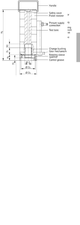
Prestressing of fastening bolts by hydraulic tension cylinder (Stretch method)
Tests and practical experience have shown time and again that the calculated torques for bolts > M 30 or 11/4“ are not coinciding with the actual values with adequate precision.
The main influential factor for these differences is thread friction in the bolt and nut contact area, for which to a large extent only empirical or estimated values are available. The effective friction force is determined by the friction coefficient. In addition, a bolted connection will undergo settling which is predominantly caused by the smoothing out of surface irregularities.
As these factors are of considerable importance in calculating the tightening torque, they can lead to substantial bolt stress variations.
The following lists of factors influencing friction coefficient variations are to
illustrate this uncertainty:
1) Thread friction is a function of:
●the roughness of the thread surface i.e. the way how the thread is produced, whether cut or rolled
●surface roughness, i.e. bright, phosphated or blackened;
●type of lubrication: dry, lightly oiled, heavily oiled;
●surface treatment of the mother thread;
●inserted thread length;
●possibly repeated tightening and loosening of the bolts.
2)Friction variations between head or nut contact area are a function of:
●roughness of the contact surfaces;
●surface condition (dry, lubricated, painted);
●hardness differences between the contact surfaces or material pairing;
●dimensional and angular deviations between contact surfaces.
The factors influencing the bolt stress can most effectively be reduced by using hydraulic tension cylinders, especially in the case of larger-diameter bolts. Compared with the conventional torque method, the tension cylinder offers the advantage of eliminating the additional torsional and bending stresses over the bolt cross section. Even more decisive is the lack of any type of friction which allows to precisely determine the remaining bolt prestress by previous tests, taking into account respective design parameters.
It is possible to calculate with a tightening factor of A of 1.2 to 1.6, depending on the diameter/length ratio, and to use the yield point of the bolt up to 90%. The prestress of the bolt tightened first is influenced by the tightening of the other bolts so that a minimum of two passes is required.
This will at the same time compensate for the settling produced by the smoothing out of the unloaded mating surface during prestressing (thread and nut contact area).
Table 7 shows the theoretical tension forces for a selected bolt series.
Due to the non-parallelism between nut and contact area and the thread tolerance, settling phenomena after the nut has been thightened cannot be included by this method either. (It is recommended to request the bolts and nuts manufacturer to observe strict squareness tolerances.)
As the tension force applied in this method will not only cause elongation in the shaft but also in the thread, it is important to choose the correct thread series or thread tolerances acc. to DIN 2510. An inadequate thread clearance may cause jamming of the nut, when the bolt is elongated. Taking into aaccount the nut height consultation with the bolts manufacturer is absolutely necessary.
The bolts should be long enough to leave at least 1 · d above the nuts free for positioning the tension cylinder.
The exact minimum lenght will depend on the strength class of the bolts and the tensioning tool used. Washers should be large enough to be pressed onto contact surface by the tension cylinder during bolt thightening. Enlarged washers should be preferred over standardised washers. Consultation with the tension cylinder supplier is necessary.
Hydraulic tension cylinders often require more space than torque spanners, because the entire device must be positioned in the bolt axis.
We recommend to use bolt tension cylinders by  GmbH, Auf’m Brinke 18, D-59872 Meschede, Germany. The following tables show the tension forces and dimensions for single and multistage bolt tension cylinders.
Torque spanners for bolts requiring torquetype prestressing can also be obtained from  .
.
Information available upon request.
20
®
Rothe Erde Large-Diameter
Antifriction Bearings
Table 5: Single-stage bolt tension cylinders
|
Cat.- |
Tension |
|
Thread dia. |
|
|
|
|
|
|
|
Type |
No. |
force in kN |
|
D1 |
D2 |
D3 |
D4 |
H1 |
H2 |
H3 |
|
ES20 |
33.10040 |
200 |
M |
20 x 2.5 |
42 |
52 |
65 |
6 |
19 |
94 |
|
ES24 |
33.10041 |
290 |
M |
24 x 3 |
49 |
60 |
78 |
8 |
22 |
102 |
|
ES27 |
33.10042 |
380 |
M |
27 x 3 |
55 |
67 |
86 |
10 |
25 |
108 |
|
ES30 |
33.10043 |
460 |
M |
30 x 3.5 |
61 |
74 |
97 |
12 |
27 |
107 |
|
ES33 |
33.10044 |
570 |
M |
33 x 3.5 |
66 |
80 |
105 |
14 |
29 |
115 |
|
ES36 |
33.10045 |
670 |
M |
36 x 4 |
71 |
86 |
117 |
16 |
32 |
118 |
|
ES39 |
33.10046 |
800 |
M |
39 x 4 |
77 |
94 |
124 |
15 |
34 |
128 |
|
ES42 |
33.10047 |
920 |
M |
42 x 4.5 |
83 |
102 |
137 |
20 |
37 |
134 |
|
ES45 |
33.10048 |
1080 |
M |
45 x 4.5 |
89 |
110 |
148 |
22 |
39 |
135 |
|
ES48 |
33.10049 |
1220 |
M |
48 x 5 |
94 |
116 |
158 |
24 |
42 |
140 |
|
ES52 |
33.10050 |
1450 |
M |
52 x 5 |
102 |
126 |
166 |
28 |
46 |
151 |
|
ES56 |
33.10051 |
1680 |
M |
56 x 5.5 |
106 |
135 |
181 |
31 |
49 |
158 |
|
ES60 |
33.10052 |
2010 |
M |
60 x 5.5 |
114 |
142 |
199 |
34 |
52 |
167 |
|
ES64 |
33.10053 |
2210 |
M |
64 x 6 |
120 |
150 |
206 |
37 |
55 |
172 |
|
ES68 |
33.10054 |
2600 |
M |
68 x 6 |
124 |
155 |
228 |
40 |
58 |
180 |
|
ES72 |
33.10055 |
2880 |
M |
72 x 6 |
130 |
168 |
238 |
44 |
62 |
186 |
|
ES80 |
33.10056 |
3610 |
M |
80 x 6 |
142 |
188 |
267 |
50 |
68 |
202 |
|
ES90 |
33.10057 |
4650 |
M |
90 x 6 |
160 |
210 |
300 |
58 |
77 |
220 |
|
ES100 |
33.10058 |
5830 |
M |
100 x 6 |
178 |
237 |
340 |
66 |
85 |
240 |
|
|
|
|
|
|
|
|
|
|
|
|
|
Table 6: Multi-stage bolt tension cylinders
|
|
Cat.- |
Tension |
|
Thread dia. |
|
|
|
|
|
|
Type |
|
No. |
force in kN |
|
D1 |
D2 |
D3 |
H1 |
H2 |
H3 |
|
MS |
20 |
33.10090 |
200 |
M |
20 x 2.5 |
43.3 |
51 |
6 |
19 |
156 |
|
MS |
24 |
33.10091 |
290 |
M |
24 x 3 |
50 |
59 |
8 |
24 |
192 |
|
MS |
27 |
33.10092 |
380 |
M |
27 x 3 |
55 |
65 |
10 |
25 |
188 |
|
MS |
30 |
33.10093 |
460 |
M |
30 x 3.5 |
61 |
73 |
12 |
27 |
182 |
|
MS |
33 |
33.10094 |
570 |
M |
33 x 3.5 |
66 |
80 |
14 |
29 |
198 |
|
MS |
36 |
33.10095 |
670 |
M |
36 x 4 |
71 |
84 |
16 |
32 |
246 |
|
MS |
39 |
33.10096 |
800 |
M |
39 x 4 |
77 |
90 |
18 |
34 |
260 |
|
MS |
42 |
33.10097 |
920 |
M |
42 x 4.5 |
83 |
98 |
20 |
37 |
253 |
|
MS |
45 |
33.10098 |
1080 |
M |
45 x 4.5 |
89 |
107 |
22 |
39 |
256 |
|
MS |
48 |
33.10099 |
1220 |
M |
48 x 5 |
94 |
112 |
24 |
42 |
265 |
|
MS |
52 |
33.10100 |
1450 |
M |
52 x 5 |
102 |
123 |
28 |
46 |
278 |
|
MS |
56 |
33.10101 |
1680 |
M |
56 x 5.5 |
106 |
129 |
31 |
49 |
288 |
|
MS |
60 |
33.10102 |
2010 |
M |
60 x 5.5 |
114 |
136 |
34 |
52 |
328 |
|
MS |
64 |
33.10103 |
2210 |
M |
64 x 6 |
120 |
150 |
37 |
55 |
330 |
|
MS |
68 |
33.10104 |
2600 |
M |
68 x 6 |
126 |
155 |
40 |
58 |
346 |
|
MS |
72 |
33.10105 |
2880 |
M |
72 x 6 |
130 |
164 |
44 |
62 |
358 |
|
MS |
80 |
33.10106 |
3610 |
M |
80 x 6 |
142 |
183 |
50 |
68 |
385 |
|
MS |
90 |
33.10107 |
4650 |
M |
90 x 6 |
160 |
203 |
58 |
77 |
418 |
|
MS 100 |
33.10108 |
5830 |
M |
100 x 6 |
178 |
232 |
66 |
85 |
446 |
|
|
|
|
|
|
|
|
|
|
|
|
|
|
21

®
Rothe Erde Large-Diameter
Antifriction Bearings
Table 7: Bolt tension forces including tolerances for “large-clearance metric thread”
– DIN 2510 – Sheet 2 – using hydraulic tension cylinders
Strength class to DlN/lSO 898 |
|
|
8.8 |
|
10.9 |
|
|
Yield point Rp 0,2 N/mm2 |
|
|
660 |
|
940 |
|
|
|
|
Tolerances to DIN 2510 |
|
|
|
|
|
Metric |
|
Tension |
Core |
Tension |
Theoretical |
Tension |
Theoretical |
ISO-Thread |
|
cross-section |
cross-section |
force at |
use of tension |
force at |
use of tension |
DIN 13 |
|
|
|
yield point |
force |
yield point |
force |
Nominal dia. |
Pitch |
AS |
A3 |
F0,2 |
FM= 0,9 · F0,2 |
F0,2 |
FM= 0,9 · F0,2 |
mm |
mm |
mm2 |
mm2 |
N |
N |
N |
N |
16 |
2 |
148 |
133 |
94700 |
85200 |
139100 |
125200 |
20 |
2.5 |
232 |
211 |
153000 |
137000 |
218000 |
196000 |
24 |
3 |
335 |
305 |
221000 |
199000 |
315000 |
283000 |
27 |
3 |
440 |
404 |
290000 |
261000 |
413000 |
372000 |
30 |
3.5 |
537 |
492 |
354000 |
319000 |
504000 |
454000 |
33 |
3.5 |
668 |
617 |
440000 |
396000 |
627000 |
564000 |
36 |
4 |
786 |
723 |
518000 |
466000 |
738000 |
664000 |
39 |
4 |
943 |
873 |
622000 |
559000 |
886000 |
797000 |
42 |
4.5 |
1083 |
999 |
714000 |
642000 |
1018000 |
916000 |
45 |
4.5 |
1265 |
1174 |
834000 |
750000 |
1189000 |
1070000 |
48 |
5 |
1426 |
1320 |
941000 |
846000 |
1340000 |
1206000 |
52 |
5 |
1707 |
1590 |
1126000 |
1013000 |
1604000 |
1443000 |
56 |
5.5 |
1971 |
1833 |
1300000 |
1170000 |
1852000 |
1666000 |
64 |
6 |
2599 |
2426 |
1715000 |
1543000 |
2443000 |
2198000 |
72 |
6 |
3372 |
3174 |
2225000 |
2002000 |
3169000 |
2852000 |
80 |
6 |
4245 |
4023 |
2801000 |
2520000 |
3990000 |
3591000 |
90 |
6 |
5479 |
5226 |
3616000 |
3254000 |
5150000 |
4635000 |
100 |
6 |
6858 |
6575 |
4526000 |
4073000 |
6446000 |
5801000 |
The mating structure must be dimensioned to allow sufficient space for the tightening tool – see Tables 5 and 6.
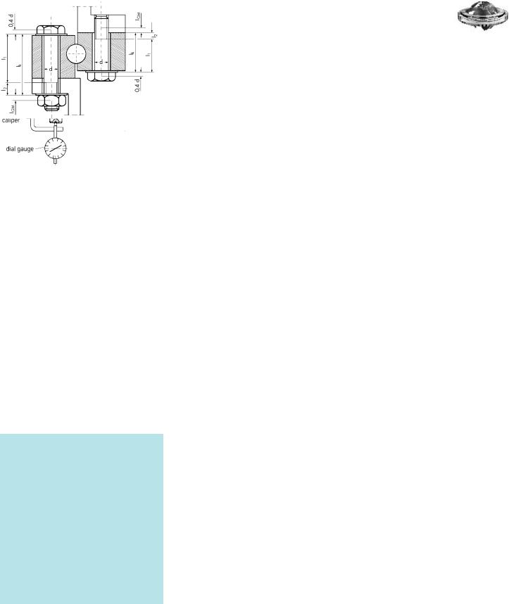
Determination of tightening torques for fastening bolts > M 30 or 11/4“
Tightening torque variations can be considerably reduced if the tightening torque for bolts > M 30 or 11/4“ is not theoretically determined but by the longitudinal elongation of the bolt.
This procedure can be easily performed if both bolt ends are accessible in the bolted condition. Structures not allowing this will requie ed a model test (Fig. 7, Page 23).
The equivalent clamping length must be simulated by identically dimensioned steel blocks. The condition of the surface underneath the turned part (bolt head or nut) should also be identical with the object itself. Generally hardened and tempered washers are used, so that these conditions can be easily complied with. The influence of a different number of joints is hardly measurable and can therefore be neglected.
The expected standard variation must be taken into account in the calculation of the tightening torque. The test is to assure that the minimum clamping force of these larger bolts is within the values assumed in the calculation.
For the bolt to be used, the elastic longitudinal elongation at 70 % prestress of the yield point is determined theoretically via the elastic resilience of the bolt with respect to its clamping length.
The bolt is prestressed until the previously determined bolt elongation I is displayed on the dial gauge. This torque is then read off the torque spanner. To account for any variations, an average value from several measurements should be determined.
When using a torque spanner with wrench socket, the measuring caliper must be removed during tightening of the nut, and the test bolts should be provided with center bores at both ends in order to avoid errors due to incorrect positioning of the measuring caliper, (Fig. 6, Page 23).
All fastening bolts on the bearing are then prestressed to this tightening torque using the same torque spanner as in the test. It must be assured that the actual bolts used and the test bolts come from the same production batch.
22
®
Rothe Erde Large-Diameter
Antifriction Bearings
|
Symbols used |
|
|
|
|
AN |
Nominal bolt cross section ......................................................................... |
mm2 |
|
|
A3 |
Thread core cross section .......................................................................... |
mm2 |
|
|
AS |
Bolt thread tension cross section................................................................. |
mm2 |
|
|
ES |
Young‘s modulus of the bolt .......................................................... |
205 000 N/mm2 |
|
|
FM |
Mounting tension force.............................................................................. |
N |
|
|
F0.2 |
Bolt force at minimum yield point ................................................................ |
N |
|
|
||||
|
I1 |
Elastic bolt length..................................................................................... |
mm |
|
|
I2 |
Elastic thread length ................................................................................. |
mm |
|
|
I |
Linear deformation at bolt tightening............................................................ |
mm |
|
|
S |
Elastic resilience of the bolt ........................................................................ |
mm/N |
|
|
Rp 0.2 |
Tension at yield point of bolt material ........................................................... |
N/mm2 |
|
|
Ik |
Clamping length of the bolt ........................................................................ |
mm |
|
|
IGM |
Thread length IG and nut displacement IM · IGM = IG + IM used in |
|
|
|
|
calculating the resilience of the inserted thread portion ................................ |
mm |
|
|
|
|
|
|
Fig. 6
After a certain operating time the bolt connection must be rechecked for prestress and regtightened, if necessary. This is required to compensate for any settling phenomena which might reduce the bolt prestress.
The required longitudinal elongation is theoretically determined by the elastic resilience of the bolt.
This gives
= –––––I E · A
S = K + 1 + 2 + GM |
|
||||||
|
|
|
|
|
|
inserted thread portion |
|
|
|
|
|
|
|
||
|
head shaft |
not inserted thread portion |
|||||
with IG = 0,5 d and IM = 0,4 d |
|||||||
for nuts ac. to DIN 934 |
|
||||||
S = |
|
0.4 d |
I1 |
I2 |
|||
––––––– + |
–––––––+ |
–––––––+ |
|||||
|
ES · AN |
ES · AN |
ES · A3 |
||||
|
|
0.5· d |
0.4 · d |
|
|||
|
––––––– + |
––––––– |
|
||||
|
ES · A3 |
ES · AN |
|
||||
The force allocated to the elastic longitudinal elongation is:
FM= |
I |
[N] |
––· I |
||
|
S |
|
Determination of the prestressing force using 70% of yield limit relative to the tension cross section:
FM |
= 0.7 · Rp 0,2 · AS |
[N] |
F0,2 |
= Rp 0,2 · AS |
[N] |
Rp 0,2 |
for strength class 8.8 |
|
|
= 640 N/mm2 for d ≤ 16; |
|
|
= 660 N/mm2 for d > 16. |
|
Rp 0,2 |
for strength class 10.9 |
|
|
= 940 N/mm2 |
|
Rp 0,2 |
for strength class 12.9 |
|
|
= 1100 N/mm2 |
|
Therefore: |
|
|
I |
= FM · S |
[mm] |
Fig. 7
23
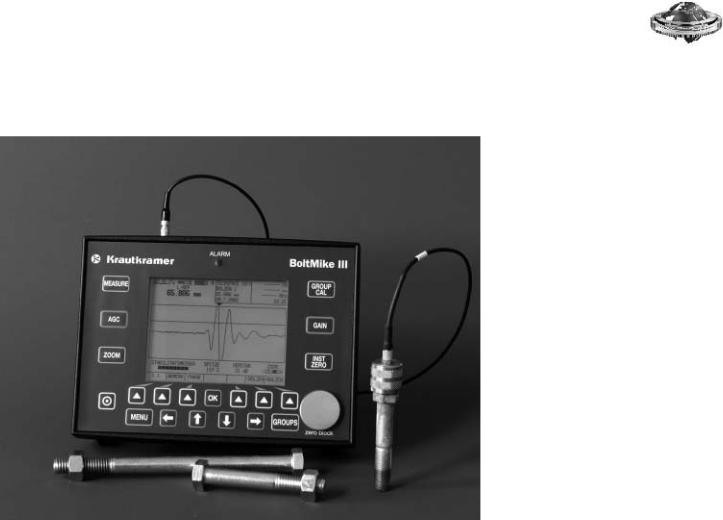
Stress measurement on bolts.
Fig. 8: Boltmike III + Data storage
Conventional methods for stress measurement of bolts, e.g. torque/angle of rotation, controlled tightening, are frequently inaccurate, difficult to document and are rarely able to be checked after tightening has been made. Other methods, such as wire strain gauge, are costly, impractical or not applicable if only one side of the bolt is accessible, as in the case of elongation measurements using a micrometer.
With the new battery driven Boltmike III
you now have a handy instrument which, on the basis of the ultrasonic time of flight measurement, ensures that you obtain an accurate and practical measurement of stress, elongation and load during tightening and at later inspections.
●The stress is directly measured in the bolt during tightening.
●The stress on the tightened bolt can be checked at any time.
●The bolt need only be accessible from one side.
●The bolt head and/or surface at the threaded end need to be plane-parallel.
●Before tension is applied, the length of the bolt is measured by the instrument and stored; a mechanical measurement of the length is not necessary.
●The calibration for normal bolt materials is preset in the instrument. New materials can be additionally programmed.
●The instrument directly displays the elongation, stress and clamping force; this saves you the trouble of converting with timeconsuming calibration factors.
Agfa NDT GmbH
Krautkramer Ultrasonic Systems
Robert-Bosch-Strasse 3
D-50354 Hürth (Efferen)
Tel.: |
+49-22 33-601-0 |
Fax: |
+49-22 33-601-402 |
E-Mail: |
hotline@agfaNDT.de |
www.AgfaNDT.com
®
Rothe Erde Large-Diameter
Antifriction Bearings
24

Loctite-586/Loctite-275
Improvement in the frictional bond.
Bearing installation using Loctite-586 |
Dismantling |
Loctite-275 |
®
Rothe Erde Large-Diameter
Antifriction Bearings
The roughness of the surface to be joined should not exceed a value of Rt 65 (peak-to-valley height) since shear strength will decrease at greater roughness values.
Theoretically, the quantity required for a layer of 0.1 mm is 100 ml/m2. However, if the layer is to be applied by hand, it is advisable to use double or triple this quantity, since dosage by hand cannot always be absolutely accurate.
The following points must be observed during installation:
1)Cleaning of contact surfaces with a commercially available cleaning agent to remove any oil or grease
2)Inactive surfaces must be pretreated with the T 747 activator. Loctite-586 must only be applied to the nonactivated surface. If both sides are active, or if Loctite is applied onto the activator, premature curing may result
(drying within a few minutes).
3)Loctite must be applied with a stiff brush onto one surface.
4)Spigot locations must not come into contact with Loctite since this would render later dismantling difficult. They must be coated with a separating agent, e.g. wax or grease.
5)Tightening of fastening bolts. Loctite will start curing as soon as 2 hours after positioning of the bearing. If it is not possible to fully tighten the bolts during this period, manual tightening will suffice as a preliminary solution.
As already mentioned, the Loctite joint will resist compressive and shear forces, but not tension. Therefore, separating the bearing from its companion structure does not present any difficulties.
When using Loctite, the best solution is to incorporate tapped holes for jacking screws right at the design stage of the companion structure. For large and heavy bearings and/or a horizontal axis of rotation, the use of jacking screws is imperative, especially when the mounting space is restricted.
To lift the bearing off, the jacking screws are tightened consecutively until the bearing works itself free.
With smaller bearings and easily accessible mounting space, it may suffice to carefully lift the bearing at one side, e.g. by applying a pinch bar at several points around the circumference.
Under no circumstances should the bearing be suspended from eye bolts and lifted off before the joint has been released in the manner described above.
Before reassembly, the surfaces are best cleaned by means of a wire brush.
Depending on the bearing size, mounting time and time of first load application, Loctite-275 may be used instead.
For this Loctite type the final strength will be reached within 3 to 6 hours at room temperature.
The properties of Loctite-275 as well as the application conditions and prerequisites for its use correspond to those described for Loctite-586.
25
®
Gearing.
Rothe Erde Large-Diameter
Antifriction Bearings
Rothe Erde large-diameter bearings are in the majority of cases supplied with spur gears. A gear cut into one of the bearing rings offers the advantage that an additional driving gear wheel is not required, which helps to reduce design work and costs.
All bearings depicted with gears are, of course, available ungeared.
Special gear types, including those for bearings with diameters exceeding those shown in this catalogue are also available upon request.
The permissible tangential forces are listed in the respective tables. The values shown refer to the bending stress at the root of the tooth.
The permissible bending stress for normalized gear material is:
130 N/mm2 for normal loads and
260 N/mm2 for maximum loads.
The following permissible bending stresses at the root of the tooth apply to quenched and tempered material, depending on the cross section:
Normal loads |
|
200 N/mm2 |
for small ring cross sections |
190 N/mm2 |
for medium ring cross sections |
180 N/mm2 |
for large ring cross sections |
Maximal loads |
|
400 N/mm2 |
for small ring cross sections |
380 N/mm2 |
for medium ring cross sections |
360 N/mm2 |
for large ring cross sections, see |
application conditions and special requirements, Page 35.
Higher values may be allowed for infrequently occuring extreme loads, but these would have to be approved by us.
The maximum values indicated in the “tangential forces” columns in the bearing tables refer to shock loads of short duration, utilization of the motor starting torque, or utilization of the maximum moment during breaking.
For the bending stress calculation it should, however, be noted that the meshing conditions in highly stressed gears are not comparable with those of standard gear transmissions where bearing mounting and shafts can be regarded as relatively rigid.
In large-diameter bearings, the drive is generally mounted in an overhung position. Due to the high tangential forces to be transmitted, the pinion shaft will bend. It is, therefore, not advisable to employ a contact ratio for preliminary design purposes.
In the case of highly stressed gears, a tip radius should be provided on the pinion, and in the case of tip relief, an additional radius at the tip edge will be necessary (see Page 27).
The bearings listed in the tables are mainly provided with an addendum modification. Addendum modification coefficient x = 0.5 (see DIN 3994, 3995).
For gears subjected to high tooth flank stress, hardened gears have proven very satisfactory. Depending on module and ring diameter, the gear rings are subjected to spin hardening or individual tooth induction-hardening, the latter predominantly in the form of tooth contour hardening. Both methods provide improved flank load carrying capacity as well as higher tooth root strength. Flank hardening with hardness phase-out in the region of the root radii leaving the root radius unhardened will reduce the load capacity at the root. Hardened gears will require an individual calculation.
We need to know the pinion data in order to be able to check the meshing geometry.
During the installation of the large-diameter bearing and the drive pinion, adequate backlash must be assured.
The backlash is adjusted at 3 teeth marked in green and is to be at least 0.03 x module.
After final assembly of the equipment and after tightening all of the fastening bolts, the backlash must be checked using a feeler gauge or a lead wire.
Fig. 9: Spin hardening
Fig. 10: Tooth contour hardening
Fig. 11: Tooth flank hardening
Fig. 12: Backlash
26
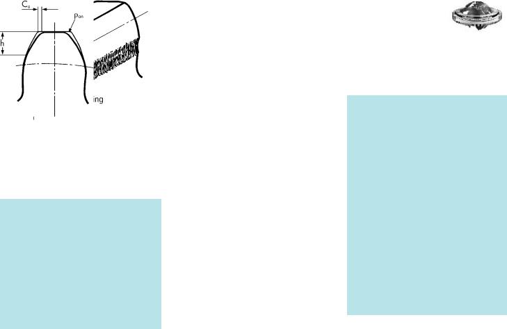
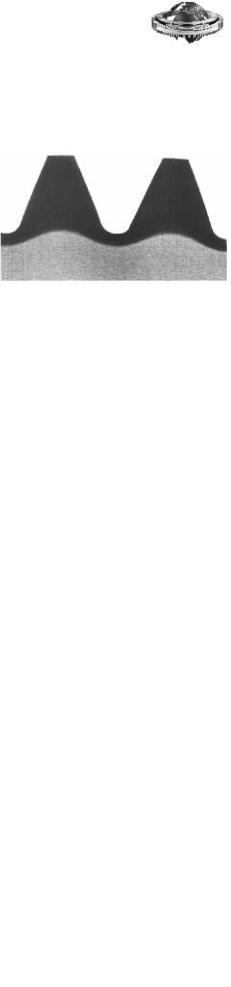
Pinion tip relief.
Despite geometrically correct profiles and theoretically adequate gears, meshing problems may still occur in highly stressed gears, e.g. “scuffing” or “chipping” at the dedendum flank of the wheel, as shown in Fig. 13.
Fig. 13
This phenomenon occurs primarily in gears with hardened pinions where the tip edges of the pinion act as scrapers.
Various causes may be responsible.
Bending
Dynamic load peaks under high force applications, accelerations, braking actions or vibrations will cause elastic deformations in the meshing teeth.
Pitch errors
Manufacturing tolerances in gears cannot be prevented, especially pitch errors, which in combination with the bending effect can produce negative influences.
Drive unit
Most slewing drive units are mounted in an overhung arrangement, and deflections of the pinion shaft are unavoidable. The high forces will simultaneously produce elastic deformations at the interface of the slewing drive and mounting structure. Such deformations may also lead to meshing problems.
Lubrication
The three influential factors mentioned will result in high peak loads acting on the tip edge of the pinion, which can cause the lubricant film to break.
The direct metallic contact will increase the chipping effect.
Occasional damage which has occurred in the past, can now be prevented by providing a tip relief at the pinion and a radius at the tip edge of the pinion.
Tip relief has become a means of reducing the effects of vibration (noises) in high-speed gear mechanisms.
Investigations have led us to specify pinions |
|
with a tip edge radius of 0.1 – 0.15 times |
|
module for applications with extreme load |
Fig. 14 |
conditions. |
|
The radius must blend into the addendum flank |
|
without forming an edge. |
|
®
Rothe Erde Large-Diameter
Antifriction Bearings
Ca |
= 0.01 · m |
|
h |
= 0.4 – 0.6 · m |
|
Ca:h |
= 1: 40 – 1: 60 |
|
|
(based on full |
|
|
tooth high) |
|
an |
ca. 0.1 – 0.15 · m |
|
27

®
Turning torque calculation.
Rothe Erde Large-Diameter
Antifriction Bearings
The calculation of the torque Mr, detailed below is based on theoretical and empirical knowledge. The torque is affected by the rolling friction coefficient, the rolling elements, spacers, seals, load distribution and the load.
Some other factors affecting the torque are:
–The out-of-flatness including the slope of the upper and lower companion structure.
–The grease filling and the type of grease.
–The lubrication of the lip seals and the seal preload.
–The variation in the bearing‘s clearance resulting from installation.
The torque calculated is, of course, subject to certain fluctuations, which can be estimated with approx. ± 25 %.
1.Starting Torque Mr
Ball bearing slewing rings
Mr = ––(4.4 · Mk + Fa · DL + 2
2.2 · Fr · DL · 1.73)
Roller bearing slwing rings
Mr = ––(4.1 · Mk + Fa · DL + 2
2.05· Fr · DL)
2.Power of Inertia
PBeh. = Mr · · –1
Mr · n
= ––––––––––
9.55 ·
[kNm]
[kNm]
[kNm · s–1]
[kW]
Specially designed bearings with reduced torque can be supplied. Please contact us regarding the applications for such bearings.
In order to assess the total moment necessary for rotating the bearing, the acceleration power of all the individual masses must still be configured as a product using the squared distance of their centres of gravity from the axis of rotation. The strength of the wind, which may possibly act upon the bearing, and any component parts under slope must also be taken into account.
Symbols used
Fa |
= axial load |
[kN] |
|||
Fr |
= radial load |
[kN] |
|||
Mk |
= resulting tilting moment |
[kNm] |
|||
DL |
= bearing race diameter |
[m] |
|||
|
= friction coefficient |
|
|
|
|
|
= angular velocity |
|
|
|
|
|
· n |
|
–1 |
|
|
|
= –––– |
[s |
] |
||
|
|||||
|
30 |
|
|
|
|
n= number of bearing revolutions
per minute |
[min–1] |
= drive efficiency |
|
Various friction coefficients |
|
= 0.008 for Type KD 210 (Type 13 and 21, normal bearings)
0.006 for Type KD 210 (Type 110)
0.004 for Type KD 320
0.006 for Type KD 600
0.003 for Type RD 700
0.004 for Type RD 800
0.003 for Type RD 900
For precision bearings, bearings without clearance and preloaded bearings, the turning torque calculation has to be performed by Rothe Erde.
28