

TREADWALL® M4 Install Manual
Model Pro
The manual is arranged as a checklist. As you go through we encourage you to check off the steps.
The Treadwall is a large, but not complicated machine. None of the steps in this manual are particularly difficult, but it is important to follow all of the steps carefully. The order of assembly is important at certain points, so read each page.
The drawings on the following pages clarify some of the trickier points. We suggest you review them before you begin and refer to them when noted in the manual.
IMPORTANT: The Treadwall transformer is designed for use with 110 volt 60 or 50 cycle AC current. It supplies 12 volts DC at 1.5 amps to the Treadwall. Users with different supply voltages must use a conversion transformer or other means to provide the proper voltage.
Requirements:
Treadwall installation is a full day's work for two people. The installers should have mechanical aptitude and some experience with mechanical assembly.
One Stepladder six-foot and sturdy is required. If you don't have one, rent it!
Other tools:
VSR Electric drill with bits (and extension cord if it is not cordless)
Combination wrench set - particularly the sizes 3/8", 9/16", 3/4".
Socket wrench set - particularly the sizes 3/8", 9/16", 3/4".
Hammer |
8" crescent wrench |
Screwdrivers |
Tape measure |
Work gloves |
Allen wrench set |
Pair of pliers with nippers |
2 carpenter's aprons |
Knife |
Eye protection |
Vice-grip pliers |
Spray cleaner and rags |
Hand cleaner
A couple of short (3-5 foot) pieces of 2x4 wood and some misc. blocks
(1)
Pro body M4 install 090809.doc


Setup and unpacking:
Set up a neat and organized workspace. It makes the whole job more pleasant and contributes to safety. Remove the packing materials from the work area – you will be working with ladders.
You should have some sort of table-high surface to put tools and small parts on where they will be easy to find and out of the way. In addition you will need a long space out of the way where you can lay out all the long parts.
The panels go on last, so put them to one side until needed.
θRemove wrapping from large parts being careful not to damage the surfaces. Take small parts out and unwrap them. Don't unwrap the rock holds until the end.
Check the parts against the list, and look them over for shipping damage. You must make damage claims within 10 days of delivery
The panels go on last, put them aside along with the metal reinforcing bars (“stiffies”) and handholds until needed. You will also need a space big enough to lay out the long parts.
All references to “right”, “left”, “downwards”, etc refer to the finished unit as viewed from the front.
Support Frames: See diagram next page
•The support frames are left and right-handed - curve goes to the front - short shafts point inwards. The right side has a wire installed.
•Support Frame Horizontal Braces are the longest pieces of square tubing - with a single hole at each end and no tabs attached. One has two rubber bumpers.
•X- braces are long and short flat strips with holes in the ends.
(2)
Pro body M4 install 090809.doc

4 |
3 |
2 |
1 |
D |
8 |
D |
12
7
|
4 |
C |
C |
|
13 |
2 |
9 |
|
3
B B
|
|
|
Parts List |
|
|
|
|
|
|
ITEM |
QTY |
PART NUMBER |
DESCRIPTION |
1 |
|
|
|
|
1 |
1 |
right frame assembly E |
|
|
|
|
|
|
|
|
|
|
|
|||
|
2 |
1 |
left frame assembly E |
|
|
|
|
|
|
3 |
1 |
Lower horizontal |
|
|
|
|
|
|
|
|
assembly E |
|
|
|
|
|
|
4 |
2 |
turnbuckle |
|
|
|
|
|
|
7 |
1 |
angle frame D horizontal |
|
|
|
|
|
|
8 |
2 |
long x brace 2 |
|
DRAWN |
|
|
|
|
|
|
|
|
|
|
|
|
|
9 |
2 |
short x brace 2 |
|
Jeff |
1/7/2007 |
Brewer's Ledge Inc. |
|
|
12 |
4 |
bolt 3-8 x 4 1-2 with |
|
CHECKED |
|
|
|
|
|
|
washer |
|
QA |
TITLE |
|
|
A |
13 |
4 |
nut 3-8 with washer |
|
|
|
A |
|
|
|
|
|
|||||
|
|
|
|
|
|
|||
|
11 |
2 |
bearing two bolt 1.5 |
|
MFG |
Treadwall Model M Support stand |
|
|
|
|
|
flange |
|
|
assembly |
|
|
|
|
|
|
|
APPROVED |
|
|
|
|
|
|
|
|
|
|
|
|
|
|
|
|
|
|
SIZE |
DWG NO |
REV |
|
|
|
|
|
|
C |
Angle stand explosion |
|
|
|
|
|
|
|
SCALE |
SHEET 1 OF |
1 |
|
|
|
|
|
|
|
||
|
|
|
4 |
3 |
2 |
|
1 |
|

.
θAttach the horizontal brace with rubber bumpers - using “A” bolts (3/8x4 ½”) - to the lower hole at the back of the right frame. Rubber bumpers face into the frame. The same bolt holds on a short x-brace.
θRepeat on the left frame. Both x-braces should point up diagonally
θBolt on the upper horizontal with “A” bolts (3/8” x 4½”), The long x braces are attached to this horizontal at each end and point down diagonally.
θFind the two turnbuckles and turn out the two jaw ends of each turnbuckle equally to almost their maximum length.
θAttach a turnbuckle to the cross brace at each side of the Treadwall, connecting the short and long crossbraces together. Securely tighten the bolts on each jaw.
θTighten the turnbuckles evenly and firmly so that they are about the same length. You will do a final adjustment later to align the machine.
θCheck the bearings. They should be tight on the shafts and flush with the ends of the shafts.
(3)
Pro body M4 install 090809.doc

4 |
3 |
2 |
|
1 |
|
|
20 |
|
|
D |
|
|
|
D |
|
|
|
|
13 |
|
|
|
|
17 |
|
|
|
25 |
|
|
|
26 |
|
14 |
|
|
|
|
|
|
|
|
|
14 |
|
|
1 |
|
14 |
C |
|
|
13 |
C |
12 |
|
|
||
|
|
|
|
14
11
6
B |
|
|
|
B |
|
|
Parts List |
|
4 |
|
|
|
|
|
ITEM |
QTY |
PART NUMBER |
DESCRIPTION |
15 |
1 |
1 |
left frame |
|
|
|
|
|||
2 |
1 |
horizontal lower |
|
|
|
|
assembly |
|
8 |
|
|
|
|
41 right frame
51 lower shaft assembly
71 upper shaft assembly
81 shroud
114 bolt 1/2 x 3 1/2 with washer
124 nut 1/2 with lockwasher
and washer |
DRAWN |
|
13 |
4 |
bolt 3/8 x 4 1/2 with |
|
Jeff |
1/7/2007 |
|
|
|
|
Brewer's Ledge Inc. |
|
|
|
||
|
CHECKED |
|
|
|
|
|
|
|
|
|
|
|||||
|
|
|
washer |
|
|
|
|
|
|
|
|
|
|
|
|
|
|
|
|
|
|
|
|
|
|
|
|
|
|
|
|
|
|
|
|
|
|
|
|
|
|
|
TITLE |
|
|
|
|
|
||
|
14 |
12 |
nut 3/8 with lockwasher |
|
|
|
|
|
|
|
|
|||||
A |
QA |
|
|
|
|
|
|
|
|
|
A |
|||||
|
|
and washer |
|
|
|
|
|
|
|
|
|
|
|
|
||
|
|
|
|
|
|
|
|
|
|
|
|
|
|
|
|
|
|
15 |
4 |
bolt 3/8 x 1 with |
MFG |
|
|
Treadwall MODEL M Frame assembly |
|||||||||
|
|
|
|
|||||||||||||
|
|
|
lockwasher and washer |
|
|
|
|
|
|
|
|
|
|
|
||
|
|
|
APPROVED |
|
|
|
|
|
|
|
|
|
|
|||
|
|
|
|
|
|
|
|
|
|
|
|
|
|
|
|
|
|
17 |
4 |
bolt 3/8 x 3 |
with washer |
|
|
|
|
|
|
|
|
|
|
|
|
|
18 |
1 |
back-guard |
|
|
|
|
|
SIZE |
|
DWGframeNO with shroud |
|
REV |
|||
|
|
|
|
|
|
C |
|
|
explosion 3 |
|
|
|
||||
|
|
|
|
|
|
|
|
|
|
|
|
|
||||
|
25 |
2 |
x brace inside |
|
|
|
|
|
|
|
|
|||||
|
|
|
|
|
|
|
|
|
|
|
|
|||||
|
26 |
1 |
spacer tube |
|
|
|
|
|
SCALE |
|
|
|
SHEET 1 |
OF 1 |
||
|
|
|
|
|
|
|
|
|
|
|||||||
|
|
|
4 |
3 |
2 |
|
|
|
|
|
1 |
|
|
|
||

Core wall assembly: See drawing - facing page
The M4 core section has two channel-frames and various shafts and horizontals that connect them together. You assemble it face down on the ground, and lift it into position.
The right frame is the one with the control panel box premounted.
Assemble starting from the top – the top shaft and top horizontal member - and work down. Leave bolts loose until the entire assembly is complete – then go back and do the final tightening.
Refer to the drawings to make sure you are orienting all parts correctly.
θ Lay down the two channel frames on edge. There are channels on the inside of each frame that will guide the climbing panels. Lay the channel frames on their
edges with these channels facing towards each other, about 4 feet apart. The bottom ends of the channel frames (“flared”) should be centered inside the
assembled support frame.
Prop up the channels with 2x4 blocks so that the narrower top end is off the ground, The ball valve handle should not be touching the ground.
Main Shaft
The main shaft has four bearings and three sprockets.
The end with two sprockets goes to the right.
θ The upper Horizontal (with the “tee” ends) is bolted-on along with the upper shaft. VERY IMPORTANT: The ends are oriented with the flange down – see the drawing on the next page.
ALSO IMPORTANT: The tee end of this horizontal will not fit through the opening in the channel-frame without twisting it 90 degrees. Make sure that both tee ends are in place in the channel frames and aligned before attaching either side. Use “D” bolts (½” x 4”) each side.
Leave the bolts somewhat loose.
(4)
Pro body M4 install 090809.doc

4 |
3 |
D
C
B
A
4 |
3 |
2 |
1 |
D
C
B
DRAWN |
|
|
|
|
|
|
|
|
|
Jeff |
1/12/2007 |
|
|
|
Brewer's Ledge Inc. |
|
|
|
|
CHECKED |
|
|
|
|
|
|
|
|
|
|
|
|
|
|
|
|
|
||
|
|
TITLE |
|
|
|
|
|
||
QA |
|
|
|
|
|
|
|
|
A |
|
|
|
|
|
|
|
|
|
|
|
|
|
|
|
|
|
|
|
|
MFG |
|
M4 upper right frame detail |
|
|
|
||||
|
|
|
|
|
|||||
|
|
|
|
|
|
|
|
|
|
APPROVED |
|
|
|
|
|
|
|
|
|
|
|
|
|
|
|
|
|
|
|
|
|
SIZE |
|
DWG NO |
|
REV |
|
||
|
|
C |
|
M4 top right detail |
|
|
|
||
|
|
|
|
|
|
|
|
|
|
|
|
SCALE |
|
|
|
SHEET 1 |
OF 1 |
|
|
|
|
|
|
|
|
|
|||
2 |
|
|
|
|
1 |
|
|
|
|
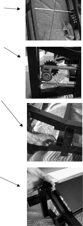
θInstall the spacer tube onto the two studs found in the middle of the channels. This tube maintains spacing in the mid-section. It will be adjusted later. The hollow ends of the tube fit over each stud. (Image shows x- bracing which goes in later)
θSlide the Bottom Axle into the bottom bearings, which come pre-mounted on the channels. Make sure the
bearings are snug against the shaft collars at each end of the shaft and tighten the setscrews on the bearings. It is much easier install the shaft if you remove one bearing from the frame. Take out the two rubber plugs and partially withdraw the two rods to remove the bearing.
There is one sliding sprocket on the bottom shaft: this goes to the right. It remains loose.
θInstall the bottom horizontal using “A” bolts (3/8” x 4½”).
NOTE: Extra washers are installed under the head of this bolt to raise the bolt up higher. There should be 3 washers under the head of the bolt (see drawing opposite page 11). Make sure the small tab with a switch is at the bottom of the bar and on the right side. Leave somewhat loose.
θAttach the “bullet” connectors on the switch to the frame wires.
θInstall the Rear Guard using “A” bolts (3/8” x 4½”),
one each side. Leave somewhat loose.
θInstall the Bottom Plate to the bottom of the channel frames using “B” bolts (3/8” x 3”), two each side (see the exploded drawing at the beginning of this manual.) Leave somewhat loose.
(5)
Pro body M4 install 090809.doc

θInstall the two internal cross-bracing rods. These are long 3/8” rods that are threaded and bent each end. Insert each into holes in the lower horizontal. Where they cross the spacer-tube in the middle of the wall, one rod should go under and one should go over the tube so that the tube is in-between the rods.
θInsert them into upper horizontal by flexing the rods slightly, Assemble with nuts and washers.
θTighten so that threads showing at all ends are approximately even, bottom and top as well as side to side. Do not over-tighten – firm but not hard.
θTighten all the bolts you have installed. Tighten firmly, but not enough to distort the frame tubing.
θMount the Top Shroud onto the top of the channels. Use (4) “C” bolts (3/8” x 1”) that go into threaded inserts on each side. Tighten. The logo should be facing down (front of the Treadwall).
(6)
Pro body M4 install 090809.doc