

~$ install manual 1 body 01-16-07.doc |
1 |
TREADWALL® M4 Install Manual
How this manual works:
This kind of type is used for subject headings
This kind of type is used for things that you have to do, and details….
This kind of type is used to introduce parts of the machine
This kind of type is used for important points
This kind of type is used for Handy Tips
The manual is arranged as a checklist. As you go through we encourage you to check off the steps. There are detailed diagrams at the end of the manual to refer to as well
– They are very helpful!
The Treadwall is a large, but not complicated machine. None of the steps in this manual are particularly difficult, but it is important to follow all of the steps carefully. Look for Handy-Tips. They are closely guarded secrets that have been handed down from installer to installer. The order of assembly is important, so read each page.
Requirements:
Treadwall installation is a full day's work for two people. The installers should have mechanical aptitude and some experience with mechanical assembly.
One Stepladder six-foot and sturdy is required. If you don't have one, rent it!
Other tools:
VSR Electric drill with bits (and extension cord if it is not cordless)
Combination wrench set - particularly the sizes 1/2, 3/8", 9/16", 3/4".
Socket wrench set - particularly the sizes 3/8", 9/16", 3/4".
Hammer |
8" crescent wrench |
Screwdrivers |
Tape measure |
Work gloves |
Allen wrench set |
Pair of pliers with nippers |
2 carpenter's aprons |
Knife |
Eye protection |
Vice-grip pliers |
Spray cleaner and rags |
Hand cleaner
A couple of short 3-5’ pieces of 2x4 wood and some misc. blocks

~$ install manual 1 body 01-16-07.doc |
2 |
qRemove wrapping from large parts being careful not to damage the surfaces. Unwrap the holds at the end.
Some of the nuts, bolts and washers are shipped attached to the appropriate parts. These are in the proper orientation and order and they should be assembled in same fashion. In general, use a flat washer on each side on the material, with the lock washer against the nut.
qOnce the parts are unpacked and laid out, check them against the list and note any shipping damage. Damage claims can only be accepted for 10 days after delivery.
Unpacking:
Set up a neat and organized workspace. It makes the job pleasant and safe. Removing everything from the packing and discarding the packing materials is an important first step, particularly since you will be working with ladders.
HANDY TIPS: A small table for tools - parts is helpful!
The panels go on last, put them aside along with the metal reinforcing bars (“stiffies”) until needed. You will also need a long space where you can lay out the long parts.
All references to “right”, “left”. “Downwards”, etc refer to the unit in standing position, from the front.
Angle Support Frames:
The support frames are left and right-handed: the curve goes to the front. The short shafts point inwards. Note that the right side has a wire installed.
The Angle Support Horizontal Braces are long rectangular tubes with a single hole at each end and no tabs attached. The lower one has rubber bumpers which face inside towards wall.
Each Angle Support Cross Brace is a pair of (1) long and
(1) short flat strip with holes in the ends
~$ install manual 1 body 01-16-07.doc |
3 |
.
qAttach one horizontal brace to the lower hole in the right frame, near the back bottom. Note that one of the short cross brace pieces goes outside at each end as shown.
qRepeat on the left frame.
Handy-tip: Use the short braces at the bottom. Tighten bolt securely with each brace pointed up diagonally towards the other frame’s upper hole.
qPosition the ladders towards the back of the frame and bolt on the upper horizontal. The long cross bracing is attached to this horizontal at each end as shown.
The cross bracing in the back makes the frame solid.
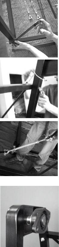
The turnbuckles for the cross bracing have jaw-style ends.
qBefore mounting, turn out the two jaw ends of each turnbuckle almost to their maximum length.
qAttach a turnbuckle at each side of the Treadwall, connecting the short and long cross-braces together. Make sure to securely tighten the bolts on each jaw.
qTighten the turnbuckles evenly and firmly so that they are about the same length
Handy-Tip: These turnbuckles keep the frame straight. For now, they are just keeping everything tight while you build the unit. You will do a final adjustment later to align the machine.

~$ install manual 1 body 01-16-07.doc |
4 |
Core wall assembly
The M4 core section is assembled on the ground, and lifted into position. This makes for easier assembly without working off ladders.
qLay down the two channel frames. Lay them on edge, front edge down, with the channels facing towards each other. The right one has the hydraulic unit mounted on it.
Prop up the channels so that the narrower top end is off the ground, The ball valve handle should not be touching the ground.
Main Shaft
Examine the main shaft before installing it on the top of the frame. It has four bearings and three sprockets. At one end of the shaft there is a single sprocket and at the other end there are two sprockets.
qNote that the end with two sprockets goes to the right.
qAssemble the upper Horizontal (with the “tee” ends) together with the Main Shaft. These get bolted on with using (4) ½” x 4” bolts each side.
You will have to put both of the two ends through the frames and then turn the bar so that the “tee” flanges face downward. Tighten.
~$ install manual 1 body 01-16-07.doc |
5 |
qSlide in the Bottom Axle into each bottom bearing which come pre-mounted on the channels. Leave loose in bearings; these will be adjusted and the set screws tightened later.
There is one loose sprocket on the bottom shaft: this goes to the right. It remains loose.
qInstall the spacer bar using the two bolts found in the middle of the channels. There should be a nut on each. First place the (2) ½” washers found in the Base Parts bag over each bolt outside the nut. You should be able to slide one end over and then the other end. Back out the nuts just enough to keep the tube from falling off. It will be adjusted later.
This bar serves to maintain spacing in the mid-section. The hollow ends of the tube fit over each bolt. (Image shows internal x-bracing which go in later)
qInstall the bottom horizontal using (1) 3/8” x 4-1/2” bolt. Make sure the small tab is facing downwards and on the right side. There is a small micro switch already mounted on this tab, be a bit careful with it. Tighten.
qInstall the Rear Guard using 3/8” x 4-½” bolts, one each side.

~$ install manual 1 body 01-16-07.doc |
6 |
qInstall the Bottom Plate to the bottom of the channel frames using 3/8” x 3” bolts, one each side. Note that on one side the holes are slotted to allow for variation in the locations. The lip goes to the rear and faces upward. Tighten.
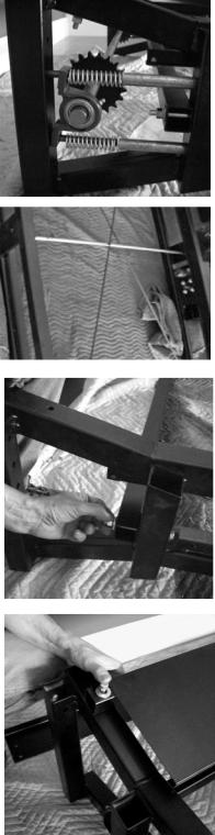
qInstall the two internal cross bracing rods. These are long 3/8” rods that are threaded each end. Insert each into holes in the lower horizontal.
qInsert them into upper horizontal by flexing the rods slightly, Assemble with nuts and washers.
qTighten so that all ends are approximately even, bottom and top.
qAdjust the spacer tube. The frames are naturally bowed inward slightly, and the spacer tube in the middle is adjusted to press them outward until they are straight. Adjust the two nuts at each end equally until the frames are the same distance apart (50 1/8”) apart at the middle as they are at the top and bottom. After this adjustment, there will only be a short length of the studs projecting into the tube ends to keep it from shifting.
qMount the Top Shroud onto the top of the channels. There are (4) 3/8” x 1” bolts that go into threaded inserts on each side. Tighten. The logo should be facing down.
HANDY TIP: The shroud may be put on later after the Core Section is lifted into place and after the chains are mounted. It is easier to see the chain sprockets without the shroud.

~$ install manual 1 body 01-16-07.doc |
7 |
Lifting the Core into place
qPlace blocks of 2x4 wood at least 24” long under the bottom of the channel frames. These should extend out so that when the core assembly is tilted upright, the foot of each channel frame is resting entirely on the blocks.
Always use a minimum of two persons to lift up the core into standing position!
Lift up the core Assembly. Make sure it is securely resting on the wood blocks.
qSlide the Angle Stand forward until the bearings are in the middle of the channel frames.
Make sure one person is always holding the core assembly at all times until it is secured to angle support frame.
qInsert the carriage bolts (1/2” x 4”) into the square holes in the Channel Frames and through the bearings. Put on the washer, lock washer and nut, but leave loose.
qUsing a lever to pry up the core assembly slightly, slip the second bolt (1/2” x 3”) into back hole of each bearing, one side at a time. Tighten all 4 bearing bolts.
qRemove the wood blocks only after you have attached the Hydraulic Angle Adjuster (below).
Mounting the Hydraulic Angle Adjuster
qMount the Angle Adjuster Cylinder using the special 3/8” x 1” “shoulder bolts at each end. Make sure to leave the valve lever closed until the unit is mounted.
HANDY TIPS: It is important to keep air from entering the cylinder. If the valve is kept closed this will not happen. Once mounted, the cylinder will operate without any air issues.

~$ install manual 1 body 01-16-07.doc |
8 |
qAttach the chrome Adjuster Lever mechanism to the valve handle.
qRemove wood blocks.
qTest the wall angle adjustment by releasing the valve and pushing the wall back, then releasing it to swing forward.
Installing the Drive Chain
The drive chain connects the pump with the main shaft. It controls the wall speed and braking.
qInstall the #40 drive chain between the pump and the sprocket on the upper shaft. Drape it over the top sprocket and attach the two ends with the attached master link. Roll it onto the bottom sprocket you have just mounted: this may require a bit of pulling.
Handy-Tip: the pump unit should be in its highest position to allow the Drive Chain to reach around the lower sprocket. It is mounted this way at the factory, but can slide down a bit, so check and correct if needed.
qUse the long tensioning bolt above the pump (on the outside of the channel frame) to push down the pump until drive chain is snug but not “bar” tight.
Handy-Tip: Important - This chain will stretch during installation and the first two weeks of use and require adjustment.

~$ install manual 1 body 01-16-07.doc |
9 |
Installing the Proximity Switch
The proximity switch is mounted on a small bracket that goes on the inside of the hydraulic unit. You will find it along with the magnets in the parts box. It is easier to install prior to installing the Main Chains. (Image to right is after chain assembly).
qAttach the proximity switch inside the hydraulic unit using the hose clamp to go around the accumulator (cast iron chamber).
qPlace the 2 magnets on the face of the bottom sprocket, opposite each other. The magnets are held onto the sprocket with magnetic attraction. Adjust the magnets until the center of the magnet passes under the proximity switch with a @1/8" gap.
qLead the wire up and to the inside of the hydraulic box. Use the wire clip to keep it in place. It attaches to the smaller female plug (only possible fit) coming off the display board. You will test this when the panel is first turned on.
The Heart Rate Receiver
qRemove the Heart Rate Receiver and bracket from their bags.
qMount the Bracket on the Spacer Tube. The narrow side goes up, the long side goes down. Lock it in place by passing a wire tie through the two holes and around the cross-brace rods. You may need to bend up the right corner to have it fit in between the rods.
qMount the receiver on the narrow top of the bracket by peeling off the tape and pressing it on. Note the label on the Receiver box: this shows the orientation of the receiver - orient it correctly and in the middle of the tube.
Check the position of the Receiver box – if it is too far to front or back, it can be hit by the moving panel stiffeners
qWrap the wire around the tube and Lead the wire up to the inside of the hydraulic box, using the wire clips to keep it in place. It attaches to the larger female plug (only possible fit) coming off the display board.

~$ install manual 1 body 01-16-07.doc |
10 |
The Main Chains:
qRemove one chain from the box. One person should unwind it while the other raises the chain over the shaft. The chains are greasy. Wear gloves & protect the floor with cardboard.
qCheck to make sure the chain tabs are facing out. These tabs are for mounting the panels.
qLift one chain up to the Top Shaft and drape it over the shaft next to a sprocket.
qMove the chain around the shaft until the two ends are equal at the bottom.
qLift the chain onto the sprocket.
qAttach the ends of the chain together under the bottom shaft using the master link on the chain. Use a length of 2x4 and a block to lever the lower shaft up while you install the chain around the lower sprocket.
HANDY TIPS: orient the master link so the spring clip is facing inward in case you have to find them later.
qRepeat for the second chain.
qAdjust both chains until they are synchronized. Before attaching the master link to the second chain, line up one of the chain tabs on each chain with the horizontal spacer bar. Check that they are aligned with the each other against the spacer bar. If the tabs don't line up, adjust the loose chain over the top sprocket. The chains must be synchronized so that the tabs with holes are directly across from each other. The Treadwall will not work otherwise.