

Professional Reading
..pdfBOSE'S APPARATUS
Bose's experiments were carried out at the Presidency College in Calcutta, although for demonstrations he developed a compact portable version of the equipment, including transmitter, receiver and various microwave components. Some of his original equipment still exists, now at the Bose Institute in Calcutta. In 1985 the author was permitted by the Bose Institute to examine and photograph some of this original apparatus.
Figure 3 (a) shows Bose's diagram of one of his radiators, used for generating 5-mm radiation. Oscillation is produced by sparking between 2 hollow hemispheres and the interposed sphere. There is a bead of platinum on the inside surface of each hemisphere. For some experiments, a lens of glass or of sulphur was used to collimate the radiation - the first waveguide-lens antenna. The lens was designed according to the refractive index measured by Bose at the wavelength in use. Figure 3(b) shows Bose's drawing of such a radiator; the sparks occur between the two outer spheres to the inner sphere, at the focal point of the lens L at the right. Bose was able to measure the wavelength of his radiation with a reflecting diffraction grating made of metal strips.
Figure 3. Bose's diagrams of his radiators. (a) shows the radiator used to generated 5-mm radiation, while (b) shows the arrangement with a lens L at the exit of the waveguide . In some designs the mounting stems for the outer spheres could be inclined to adjust the dimension of the spark gaps.
Figure 4 (a) is a photograph of one of his radiating antennas; part of the spark oscillations are generated inside the overmoded circular
waveguide. A polarizing grid is built into the antenna, clearly visible at the radiating end of the waveguide. Figure 4 (b) shows a closeup of the dual spark gaps used for the transmitter; the sparks are generated between the 2 outer spheres and the inner sphere. Figure 4 (c) shows both a transmitting antenna (left) and the receiver (right), with a dual prism in between set on the experimental rotating table.
Figure 4(a) One of Bose's transmitter antennas (being held on the right of the picture). Note the polarizing grid; the spark gap is just visible behind the grid. In the background behind this antenna part of the high voltage equipment used to generate the spark can be seen. At the left of the picture is a receiving horn.
Figure 4(b) A closeup of the spark gaps normally mounted inside the transmitting antenna
21
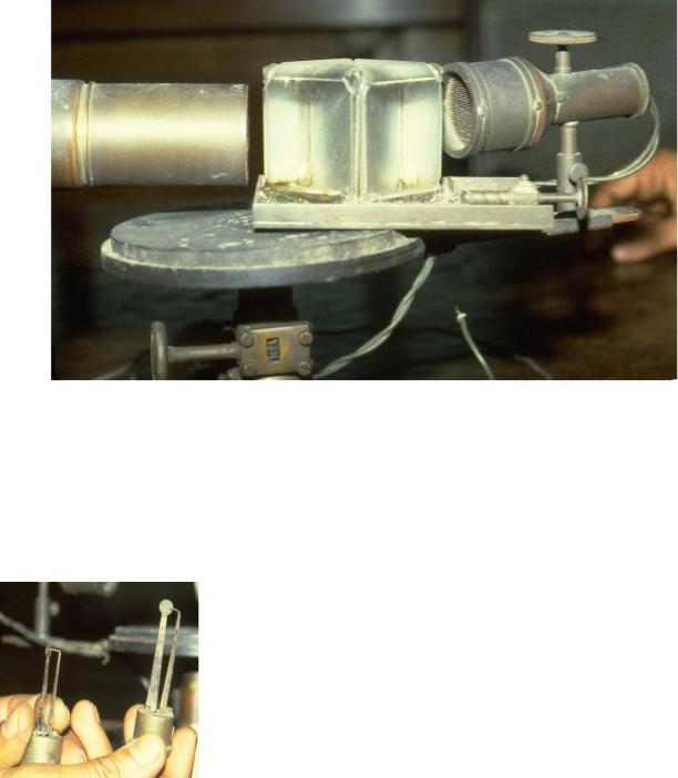
Figure 4(c) A complete setup showing the transmitting antenna at the left, with the receiving antenna at right. Note the adjustment screw on top of the receiving antenna, which is used to adjust the pressure of the point-contact detector (see Fig. 5). In the center is a rotating table (the "spectrometer circle" of Figure 2) on which various microwave components (prisms, lenses, grids, polarizers etc.) may be mounted for study. A dual-prism attenuator (see below) is shown in this photograph. The arrangement as shown is not yet properly aligned.
Figure 5 shows two of Bose's point contact detectors. In use, the detector would be placed inside an overmoded waveguide receiving antenna, very much like the transmitting antenna shown in Figure 4, and with a matching polarizing grid.
Figure 5. Two of Bose's point contact detectors, removed from the receiving antennas.
Bose measured the I-V characteristics of his junctions; an example characteristic curve of a "Single Point Iron Receiver" is shown in Figure 6. The junction consisted of a sharp point of iron,
pressing against an iron surface, with pressure capable of fine adjustment. The different curves in Figure 6 correspond to different contact pressures. Bose noted that the junction does not obey Ohm's law, and that there is a knee in the curve at approximately 0.45 volts; the junction becomes most effective at detection of short wavelength radiation when the corresponding bias voltage is applied. He made further measurements on a variety of junctions made of different materials, classifying the different materials into positive or negative classes of substance. In one experiment
22
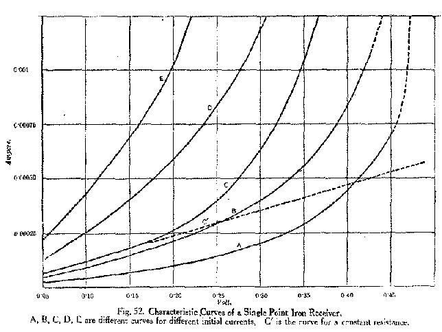
he noted that increasing the applied voltage to the junction actually decreased the resulting current, implying a negative dynamic resistance.
Figure 6. The I-V characteristics measured by Bose for a Single Point Iron Receiver. Note the similarity to modern semiconductor junctions, with a knee voltage of about 0.4 volts.
Another of Bose's short-wavelength detectors is the spiral-spring receiver. A sketch of a receiver used for 5-mm radiation is shown in Figure 7; the spring pressure could be adjusted very finely in order to attain optimum sensitivity. The sensitive surface of the 5-mm receiver was 1 by 2 cm. The device has been described recently as a "space-irradiated multi-contact semiconductor (using the natural oxide of the springs)." A surviving, somewhat larger, spiral spring receiver is shown in the photograph Figure 8. The springs are held in place by a sheet of glass, seen to be partly broken in this example.
23
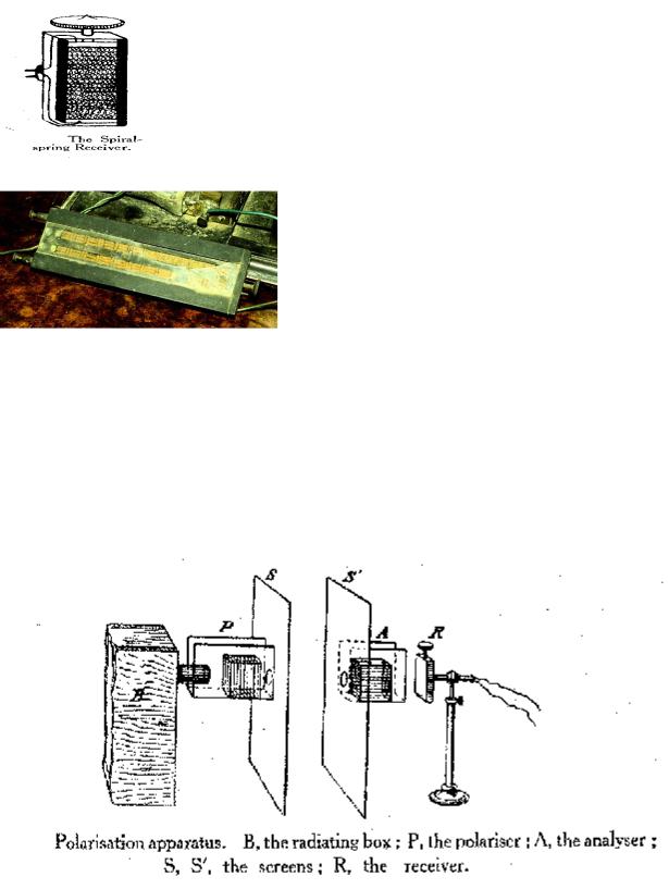
Figure 7. Bose's diagram of his spiral-spring receiver used for 5-mm radiation.
Figure 8. One of Bose's free-space radiation receivers, recently described as a "space-irradiated multi-contact semiconductor (using the natural oxide of the springs)." The springs are kept in place in their tray by a sheet of glass, seen to be partly broken in this photograph.
Figure 9 is Bose's diagram of his polarization apparatus. The transmitter is the box at left, and a spiral spring receiver ('R') is visible on the right. One of the polarizers used by Bose was a cut-off metal plate grating, consisting of a book (Bradshaw's Railway Timetable, Figure 10) with sheets of tinfoil interleaved in the pages. Bose was able to demonstrate that even an ordinary book, without the tinfoil, is able to produce polarization of the transmitted beam. The pages act as parallel dielectric sheets separated by a small air gap.
Figure 9. Bose's diagram of his polarization apparatus. Note the spiral spring receiver 'R' to the right.
24
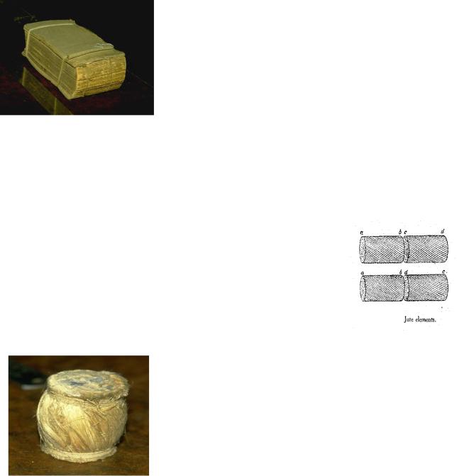
Figure 10. One of Bose's polarizers was a cut-off metal plate grating, consisting of a book (Bradshaw's Railway Timetable) with sheets of tinfoil interleaved in the pages.
Bose experimented with samples of jute in polarizing experiments. In one experiment, he made a twisted bundle of jute and showed that it could be used to
rotate the plane of polarization. The modern equivalent component may be a twisted dielectric waveguide. He further used this to construct a macroscopic molecular model as an analogy to the rotation of polarization produced by liquids like sugar solutions. Figure 11 shows Bose's diagram of the jute twisted-fiber polarization rotator, and Figure 12 is a photograph of a surviving twisted-jute polarizer at the Bose Institute.
Figure 11. Bose's diagram of twisted-Jute polarization elements, used to simulate macroscopically the polarization effect of a certain sugar solutions.
Figure 12. One of the twisted-jute polarizers used by Bose.
25
THE DOUBLE-PRISM ATTENUATOR
Bose's investigations included measurement of refractive index of a variety of substances. He made dielectric lenses and prisms; examples are visible in Figures 13 and 14.
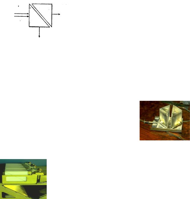
Figure 13. Bose's 1897 diagram of the double-prism attenuator.
One investigation involved measurement of total internal reflection inside a dielectric prism, and the effect of a small air gap between two identical prisms. When the prisms are widely separated, total internal
reflection takes place and the incident radiation is reflected inside the dielectric. When the 2 prisms touch, radiation propagates unhindered through both prisms. By introducing a small air gap, the combination becomes a variable attenuator to incident radiation; this is illustrated in Bose's original diagram, shown in Figure 13. Bose investigated this prism attenuator experimentally; his results were published in the Proceedings of the Royal Society in November, 1897. Schaefer and Gross made a theoretical study of the prism combination in 1910; the device has since been described in standard texts.
Figure 14. One of Bose's original double-prism attenuators, with adjustable air gap.
At the National Radio Astronomy Observatory in Tucson, Arizona a new multiple-feed receiver, operating at a wavelength of 1.3 mm, has recently been built and installed on the 12 Meter Telescope at Kitt Peak. The system is an 8-
feed receiver, where the local oscillator is injected into the superconducting tunnel junction (SIS) mixers optically. With an SIS mixer receiver the power level of the injected local oscillator is critical; each of the 8 mixers requires independent local oscillator power adjustment. This is achieved by adjustable prism attenuators. Figure 15 shows 4 of these 8 prism attenuators, installed on one side of the 8-feed system; this can be compared with Figure 14, which is a photograph taken at the Bose Institute in Calcutta in 1985, of
an original prism system built by Bose.
Figure 15. Four of the 8 double-prism attenuators used to control local oscillator injection into the NRAO 1.3-mm 8- beam receiver in use at the 12 Meter Telescope at Kitt Peak.
26
CONCLUSIONS
Research into the generation and detection of millimeter waves, and the properties of substances at these wavelengths, was being undertaken in some detail one hundred years ago, by J.C. Bose in Calcutta. Many of the microwave components familiar today - waveguide, horn antennas, polarizers, dielectric lenses and prisms, and even semiconductor detectors of electromagnetic radiation - were invented and used in the last decade of the nineteenth century. At about the end of the nineteenth century, many of the workers in this area simply became interested in other topics. Attention of the wireless experimenters of the time became focused on much longer wavelengths which eventually, with the help of the then unknown ionosphere, were able to support signalling at very much greater distances.
Although it appears that Bose's demonstration of remote wireless signalling has priority over Marconi, he was the first to use a semiconductor junction to detect radio waves, and he invented various now commonplace microwave components, outside of India he is rarely given the deserved recognition. Further work at millimeter wavelengths was almost nonexistent for nearly 50 years. J.C. Bose was at least this much ahead of his time.
27
APPENDIX
Useful expressions for translating teхts
A
according to - согласно account for - объяснять
after a while - через некоторое время after the manner - по способу
a great deal of - много
ahead of time - заблаговременно allow for - компенсировать along with - одновременно
and the like - и тому подобное any longer - уже; больше не apart from - помимо, кроме as - как, когда, так как
as a matter of fact - фактически
as close as possible - как можно точнее as a whole - в целом
as early as - уже; ещё
as for - что касается, относительно as if - как будто
as in the case - как в случае с as long as - до тех пор, пока as regards - что касается
as soon as - как только as well as – так же как
at a glance - сразу, с первого взгляда at all - вообще, совсем
at all events - при всех условиях at least - по крайней мере
at a time - одновременно at issue - рассматриваемый
at random - наугад; произвольно at the cost - за счет
at will - по желанию
28
B
be alike - быть похожим bear in mind - иметь в виду
because of - из-за, вследствие be due to - обуславливать(ся) before long - вскоре
be likely - вероятно
be of use - быть полезным be of value - иметь значение beyond doubt - несомненно
beyond question - вне сомнения
bring about - осуществлять, быть причиной bring into contact - соединять
but for - если бы не
by all means - обязательно by far - непосредственно by means of - при помощи
by no means - никоим образом by then - к тому времени
by turns - по очереди
by virtue of - благодаря, посредством
C
compatible with – совместимый
D
deal with - иметь дело depending on - в зависимости от despite - несмотря на
do without - обходиться без due - должный, надлежащий due to - вследствие, из-за
29
E
either ... or – или ... или end to end - непрерывный
even - даже, ровный, четный ever since - с того времени
F
far less - гораздо меньше
far more - значительно больше figure of merit - критерий
first rateпервоклассный for - для, в течение, так как for ever - навсегда
for lack of - из-за отсутствия former - первый
for the rest - в остальном for the sake of - ради
for the time being - на время, пока
G
get rid of - освобождаться от give rise to - вызывать
go into operation - вступать в действие greatly - очень, в значительной степени
H
have nothing to do with - не иметь никакого отношения half as much - в два раза меньше
hence - следовательно highly – весьма
I
if any - если таковые вообще имеются
30