Appendix A: Introduction to System-Level EMC Quantitative … |
331 |
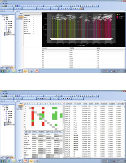
Fig. A.9 EMC Interference correlation matrix
A.5 System-Level EMC Design
This function allows the users to optimize the initial EMC design scheme based on the evaluation results. The optimization involves thirteen items including frequency design, antenna layout design, transmission power design, receiving susceptibility design, out-of-band emission attenuation design, out-of-band receiving rejection design, shielding effectiveness design, and latching design as shown in Figs. A.10, A.11, A.12, and A.13.
Fig. A.10 Frequency design
332 |
Appendix A: Introduction to System-Level EMC Quantitative … |
Fig. A.11 Frequency optimization
Fig. A.12 Frequency-using equipment parameter design
Appendix A: Introduction to System-Level EMC Quantitative … |
333 |
Fig. A.13 Shielding effectiveness design
A.6 Database Management
This function allows users to manage the model data, test data, engineering data and simulation task data. Users can build parametric model of the antenna using EMCIC, and the generated model can be used directly by common electromagnetic
Fig. A.14 EMC Parameterized Model Library
334 |
Appendix A: Introduction to System-Level EMC Quantitative … |
Fig. A.15 EMC Test Database
field simulation software to do electromagnetic calculation. In addition, the software supports the entry and maintenance of EMC test data for each equipment/subsystem on the platform. The test data can be further used for veri- fication and conformance test of the design. Figs. A.14 and A.15 illustrate the parameterized model library and the test database separately.
Appendix B
Software for Aircraft EMC Evaluation in Different Phases
In view of the difficulty in EMC evaluation during product development, based on the engineering experience of several models of aircraft development, and the different EMC requirements of aircraft systems and airborne equipment in different development phases, we developed a software for aircraft EMC evaluation management in different phases, as shown in Fig. B.1.
1.Main functions of the software
(1)Product information entry: The information that can be entered includes basic information, functional principles, product installation characteristics, EMC requirements, EMC problems, EMC design, test conditions and information of the data entry personnel.
(2)Expert scoring system: Experts will score the EMC performance of the current development phase in accordance with the input information of the product and the EMC indicator system established by the software in different development phases. Experts provide their evaluation opinions and suggestions, and the software automatically calculates the total score of the EMC condition of the product in the current development phase.
(3)Report generation: The software can generate a report in Microsoft Word format. The report covers the input EMC information of the product, as well as the expert evaluation scores, suggestions, etc.
(4)Database storage: The input EMC information of the product and expert evaluation scores, suggestions, etc., can be stored as an Microsoft Access database file, which can be called by the supporting “aircraft EMC quality management software” (Fig. B.2).
© National Defense Industry Press and Springer Nature Singapore Pte Ltd. 2019 |
335 |
D. Su et al., Theory and Methods of Quantification Design on System-Level Electromagnetic Compatibility, https://doi.org/10.1007/978-981-13-3690-4
336 |
Appendix B: Software for Aircraft EMC Evaluation in Different Phases |
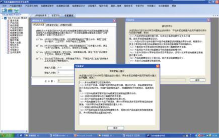
Fig. B.1 Main interface of the software for aircraft EMC evaluation management in different phases
Fig. B.2 Main functions of the software
Appendix B: Software for Aircraft EMC Evaluation in Different Phases |
337 |
2.Software modules
(1)Engineering operation module: This module allows the users to manage the product information in each phase. The product information in different phases is always stored in the same project folder, so that it is easy to create a new project or open an existing project for viewing and modification. In addition, the function of reports generation and exit are also in this module. Users can click “Generate a Report” in the file to display the information of the current project in a Microsoft Word format. Users can click “Exit” to exit the software.
(2)Product information entry module: This module allows users to enter the information of the product series in each phase. In this module, users can input basic information, product installation characteristics, EMC requirements, EMC problems, EMC design, test conditions, troubleshooting results, and information of the data entry personnel. The information of each sub-item can be modified and saved. Every piece of information entered will appear in the generated report.
(3)Evaluation module: This module allows experts to evaluate and score the product provided by the manufacturer. The software will display different scoring system in accordance with phase of the product. Using the provided scoring system, experts can evaluate the products, decide the weights of each indicator and give score (Fig. B.3); The total score of the product in this phase can then be calculated. In addition, experts can also enter corresponding evaluations and suggestions in text for the product. The text will also appear in the generated report.
Fig. B.3 Interface of the expert scoring system
338 |
Appendix B: Software for Aircraft EMC Evaluation in Different Phases |
(4)Database module: The main function of this module is to store some of the useful information of the product into a Microsoft Access database file, so that the product information in different phases can be called and compared by other database management software.
3.Applications
The software has been applied to the development of several pieces of equipment and several aircraft models in different organizations. Using this software, users can collect and analyze product’s basic information, product function and working principles, product installation characteristics, product EMC requirements, EMC design of current development phase, EMC test, EMC problems, troubleshooting measures and effect in current development phase. The software then generates EMC requirements and evaluation criteria in accordance with the development phase. Next, the product EMC is evaluated using the expert scoring method and recommendations will be provided to improve product EMC design. Finally, the software generates a comprehensive evaluation report and database files.
The software allows users to evaluate the EMC technology status of the entire aircraft and the airborne electronic equipment in each development phase, so that all users can understand the current EMC technology status of the product, so that the EMC control can be improved during development.
Appendix C
Aircraft EMC Quality Management
Software
We have developed the “aircraft EMC quality management software” for the EMC information communication for all users. The software allows users to integrate the EMC status information of each phase of the system or equipment, and add or delete the database files generated by the “software of aircraft EMC evaluation management in different phases” in batches. the EMC status data of the whole aircraft in different phases is integrated into a single database file. This way, it is convenient for users to manage and store the EMC status information of the electronic equipment of the whole aircraft. The software can also generate the EMC quality report of the whole aircraft in PDF format.
The software was developed in Microsoft Visual C++ 6.0 integrated development environment with Microsoft Access database; the overall structure of the software is in framework style. The main framework includes system menu, maximization, minimization and closing the dialogue box; the sub-frame consists of label-type frames. Each project is a sub-frame divided into two display areas. The software allows multiple projects, or product in different phases open at the same time for searching, adding and deleting the EMC equality information (Fig. C.1).
1.The main function:
(1)Database management: This function is to manage the product’s EMC status information in Microsoft Access database files. This function allows users to add, delete, search and display the files, so that all users can analyze and manage the EMC status of the aircraft.
(2)Statistics of quality management information: By gathering the EMC performance score of the whole aircraft, the software will automatically generate statistical result such as the EMC excellent rate, good rate, pass rate and failure rate of the product;
(3)Quality management report generation: The EMC status information of the whole aircraft, including the EMC quality of all equipment, can be generated into a report in PDF format.
© National Defense Industry Press and Springer Nature Singapore Pte Ltd. 2019 |
339 |
D. Su et al., Theory and Methods of Quantification Design on System-Level Electromagnetic Compatibility, https://doi.org/10.1007/978-981-13-3690-4
340 |
Appendix C: Aircraft EMC Quality Management Software |
Fig. C.1 Main interface of aircraft EMC quality management software
The “aircraft EMC quality management software” allows users to add or delete information files of different products or products in different phases, such that users can manage the aircraft EMC quality information. The software can display all information entered and highlight the expert score; it can display the manufacturer's test report; at the same time, the database centrally manages the quality information and generates quality reports. The software interface is shown in Fig. C.2.
2.Software modules
(1)Project management module: This module allows users to perform project management operations, such as create, open, save, and save as. The result of the user’s operation of the database file will be saved in the open or saved project. The project management drop-down menu has the “recently opened project” button, which makes it convenient for the user to open the last three projects that have been opened. In addition, the “exit” function is also in this menu. Users can exit the system by clicking the “Exit System” button.
(2)Report generation module: This module allows users to generate reports. There are two generation modes, one is to only generate the content of the current table into a PDF report; the other is to generate a report containing all the details on the right side.
Appendix C: Aircraft EMC Quality Management Software |
341 |
Fig. C.2 Software function interface
(3)Toolbar module: This module contains shortcuts of the menu. The shortcuts are linked with: new project, open project, save project, generate report (all information), generate report (table information), help, and about the system.
(4)Display module: The left side is the management information, which mainly displays the information list of the Microsoft Access file for current project. When a row in the list is selected, other detailed information of the row will be displayed on the right side. The information management function includes adding, deleting, and finding the Microsoft Access file in the correct format.
3.Applications
This software has been applied in the development of several aircraft models in conjunction with the “software of aircraft EMC evaluation of different phases”. The software provides a platform for users to manage the product’s information, the EMC design and the control work of each phase, such that the EMC technology status and the aircraft EMC quality can be controlled and managed.