


Appendix A: Introduction to System-Level EMC Quantitative … |
327 |
Fig. A.2 Construction of EMC geometric model of the platform
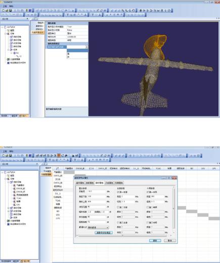
A.1 Pre-processing Function
EMCIC integrates a commercial CATIA environment and AI Environment. It has all the functions required to define complex geometries, and supports import and generation of files in CATIA, IGES, STP, and STL formats. EMCIC also supports meshing. The platform EMC collection model is constructed as shown in Fig. A.2.
A.2 Post-processing Function
Through the post-processing function, the S parameters and the Cartesian and polar plot of antenna patterns (amplitude, phase, main polarization and cross polarization, circular polarization axis ratio, phase center) can be rendered, the field strength is visualized and the EMC design reports can be generated. The visualization of an antenna pattern is shown in Fig. A.3.
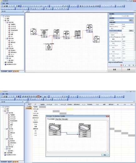
A.3 Program Management
The program management function is to model the EMC design scheme, including: basic attributes of transmitter, receiver, transceiver and non-RF equipment, as well as the construction of transmission attributes, reception attributes, case attributes, cable attributes, and interference correlation. Initial layout settings for antennas, cables, and devices on the platform are also covered in the program management function as shown in Figs. A.4, A.5, and A.6.
328 |
Appendix A: Introduction to System-Level EMC Quantitative … |
Fig. A.3 Data visualization of an antenna pattern
Fig. A.4 Parameterized modeling of equipment/subsystems
Appendix A: Introduction to System-Level EMC Quantitative … |
329 |
Fig. A.5 Behavioral modeling of equipment/subsystems
Fig. A.6 Construction of interference correlation relationship between equipment/subsystems