

8.3 The Solutions to Pass CE102, RE102, and RS103 Tests |
319 |
8.3 The Solutions to Pass CE102, RE102, and RS103 Tests
8.3.1 The EMC Failure Location
There are four main methods to locate failures in CE102, RE102, and RS103 tests:
(1)Method of exclusion: It is applicable to finding the major cause (which is a certain module) of failure in the equipment/subsystem. Using this method, we start from the equipment, and gradually check the modules and circuits. This method can locate the failure down to the equipment or circuit level.
(2)Method of replacement: Replace a circuit module in the equipment with a simulated load to determine whether the module is the main cause of the test failure. This method is simple to implement and can diagnose at the equipment or circuit level.
(3)Method of interchange: Replace a circuit module in the equipment with a circuit module without EMC problem to determine whether the circuit module is the main cause of the test failure. This method can diagnose the failure at equipment or circuit level.
(4)Method of diagnostic test: When the equipment/subsystem fails a test item, the method of diagnostic test is a convenient and effective way to determine the main factors causing the problem, such that the problem can be solved fast and accurately. Diagnostic tests generally use sensors such as probes, combined with spectrum analyzers and oscilloscopes, to test local electric field strength, magnetic field strength or time-domain waveform, amplitude, etc. Diagnostic tests sometimes do not require standard test equipment and test sites. We can use simple and versatile equipment without a high accuracy requirement. As long as the test is highly targeted, it is easy to find out the problem through testing and determine the effectiveness of the improvement measures. When using the method of diagnostic test, we can get a better result if we also combine other methods described above.
8.3.2 Trouble Shooting Suggestions
1. CE102
In Example 8.1, the failure of CE102 was because that there was no appropriate filtering added toward the power module. Therefore, in order to meet the limit requirement of CE102, it is necessary to include filtering measures such as:
(1)Install internal filter:
An EMI filter shall be installed on the 280 V bus in the case, as shown in Fig. 8.9. However, due to the space limitation in the case, the internal inductance and the capacitor component of the filter are limited in size, such that they cannot be
320 |
8 EMC Engineering Case Analysis |
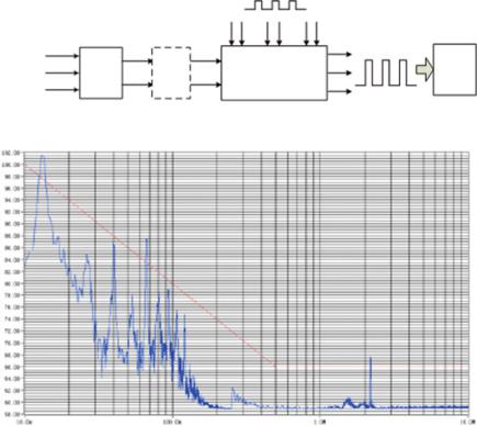
13.3kHz Low Voltage Level
PWM Signal
|
|
|
|
280V Chopped Wave |
|
Treble Phase |
Rectifier |
EMI |
|
Motor |
|
115V |
Driver Control |
||||
Filter |
|||||
|
|
||||
|
|
|
|
Fig. 8.9 Schematic diagram of EMI filter installation
Fig. 8.10 CE102 test result after installing the internal filter
well grounded, causing the performance of the filter not meeting the application requirements. After the internal 280 V DC bus was installed with the filter, there were still three frequency points failing the test, and the maximum value exceeds the limit by 4 dB, as shown in Fig. 8.10. Compared with Fig. 8.2, it can be seen that the result of CE102 has been significantly improved after the filter was installed.
(2)Install power filter:
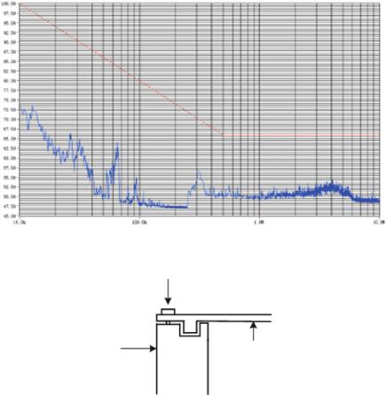
A power supply filter could be installed at the inlet of the three-phase 115 V power leads of the product. The test results showed that after the external filter was installed, the CE102 test result as shown in Fig. 8.11 can meet the standard limit value. However, the external filter was rather bulky, and the overall weight of the product increased.
Since the internal circuit board of the product has been basically determined, it is difficult to install and connect the internal filter. What’s more, it is difficult to optimize the filter parameters. The final measure is to install a power filter.
8.3 The Solutions to Pass CE102, RE102, and RS103 Tests |
321 |
Fig. 8.11 CE102 test result after installing the power filter
Screw
Case |
Case |
side wall |
top cover |
Fig. 8.12 Measures to strengthen the shielding
2. RE102
In Example 8.2, the RE102 test did not satisfy the standard limit value due to the insufficient design of the case cover. Therefore, in order to pass RE102, a more reasonable case shielding structure should be adopted as shown in Fig. 8.12.
However, because the sidewall of the case is thin, it is not suitable for this modification. The final shielding scheme is adding copper reeds at the seam between the upper cover and the sidewall of the case, thereby increasing the electrical continuity of the case.
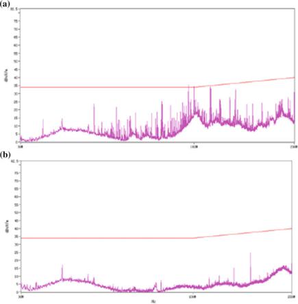
In Example 8.3, since the fan power cable was taken out from the opening of the case wall, the shielding strength of the case has been greatly reduced, resulting in a failure of the RE102 test. To solve the problem, we can connect a feed-through capacitor in series to the fan power cable and well ground the feed-through capacitor;
322 |
8 EMC Engineering Case Analysis |
Fig. 8.13 RE102 test results before and after taking measures—a the product without any measures; b after the feed-through capacitor is added to the power cable of the fan
thus, the radiation emission of the product can be greatly reduced to meet the standard limit requirement of RE102. Figure 8.13a, b shows the RE102 test result of the equipment before and after the series connection of the feed-through capacitor to the fan power cable.
3. RS103
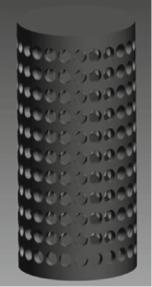
In Example 8.4, the main reason that the product failed the RS103 test was that the sensor, the transmission cable, and the connection location of the product were the main path of picking up electromagnetic energy.
According to the interference mechanism and physical structure of the front-end sensor of the product, the designed shielding structure shall not affect the physical variable that the sensor induced, and at the same time, the external electromagnetic wave shall be effectively shielded and attenuated. Therefore, the sieve structure shield
8.3 The Solutions to Pass CE102, RE102, and RS103 Tests |
323 |
Fig. 8.14 Structure of the shield
is designed based on the actual usage, as shown in Fig. 8.14. The practical application shows that the structure can effectively protect the sensor and the connecting part of the cable from the external electromagnetic environment and thus ensure the normal signal acquisition.
326 |
Appendix A: Introduction to System-Level EMC Quantitative … |
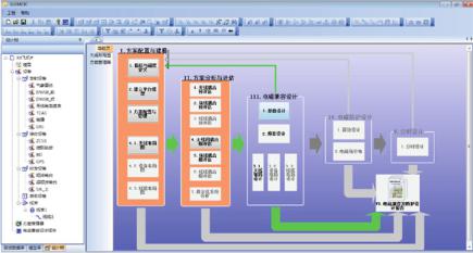
Fig. A.1 Overall software function
Table A.1 Summary of basic functions of EMCIC
Pre-processing |
Post-processing |
Program management (version control, |
Matlab (Mathworks) visualization |
create/inherit, delete, copy, etc.) |
|
Indicator customization |
Visualization of parameter S |
Software platform wizard |
Visualization of antenna pattern (2D, 3D) |
Platform import, extraction and transformation |
Visualization of the E/H near field distribution |
|
(2D, 3D) |
Antenna layout visualization and adjustment |
Report generation in the format of Microsoft |
|
Word |
Program management |
EMC evaluation |
Transmitter management |
EMC pre-analysis |
Receiver management |
EMC interference correlation matrix |
Transceiver management |
Simulation and prediction of isolation between |
|
antennas |
Non-RF equipment management |
Simulation and prediction of the near-field |
|
distribution |
Management of Interference correlation |
Simulation and prediction of antenna pattern |
relationship |
characteristics |
Management of simulation analysis |
Simulation and prediction of the shieling |
frequencies |
effectiveness |
Spectrum browsing |
Simulation and prediction of field-line coupling |
Behavioral modeling |
Simulation and prediction of line-line coupling |
System-level EMC design |
Database management |
Frequency-domain design |
Model database |
Margin design (power design, susceptibility |
Test database |
design, out-of-band emission attenuation |
|
design, out-of-band rejection design for |
|
receiver, shielding effectiveness design, layout |
|
design, protection design) |
|
Time-domain design |
Simulation task release and download |