


Chapter 4
Basic Concepts of Quantitative
System-Level EMC Design
The definition of EMC, the three aspects, and the terminologies of EMC can be found in related regulations [11, 12]. In this chapter, we will further explain these concepts from the perspective of quantitative design on system-level EMC [12].
4.1 Basic Definitions of EMC
This section presents the concepts of electromagnetic interference (EMI), electromagnetic compatibility (EMC), electromagnetic vulnerability (EMV), electromagnetic environment (EME), electromagnetic environment adaptability, spectrum management, spectrum certification, spectrum supportability, etc.
4.1.1 Electromagnetic Interference
Any electrical and electronic system will produce electronic signals or electromagnetic emissions (including intentional and unintentional) while operating. When these electronic signals or electromagnetic emissions cause undesirable or unacceptable responses, malfunctions, performance degradation, earlier-than-expected discovery, positioning, identification by the enemy, the electronic signals or electromagnetic emissions are defined as electromagnetic interference (EMI).
It should be noted that EMI includes two aspects, namely emission and susceptibility.
In order to better explain the definition, several terminologies need to be defined first:
(1)Intentional emission: It is the electromagnetic emissions generated by the system antenna in the operating frequency band.
© National Defense Industry Press and Springer Nature Singapore Pte Ltd. 2019 |
61 |
D. Su et al., Theory and Methods of Quantification Design on System-Level Electromagnetic Compatibility, https://doi.org/10.1007/978-981-13-3690-4_4
62 |
4 Basic Concepts of Quantitative System-Level EMC Design |
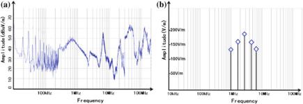
Fig. 4.1 Result of electromagnetic interference test of a system. a Electromagnetic emission; b electromagnetic susceptibility
(2)Unintentional emission: It is the electromagnetic emissions generated from the part that should not generate emissions (e.g., cables, apertures, slots, keyboards), or the electromagnetic emissions generated by the antenna outside the operating frequency band.
(3)Responses, malfunctions, performance degradation: The influence of the three on the electrical and electronic systems is progressive. Response has the lightest influence that can be perceived but will not affect the system operation; malfunction means that part of the system is affected but the overall system performance remains normal; performance degradation is the most serious, which means that the overall system performance has been affected and dropped.
(4)Discovery, positioning, identification: The three terms are progressive in degree of being discovered by the enemy. Discovery refers to the discovery of suspicious objects; positioning refers to locating of the suspicious objects; identification refers to the determination of whether the object is enemy or not and other attributes of the object.
The electromagnetic emission and electromagnetic susceptibility characteristics are inherent attributes of the electrical and electronic systems which are determined by design principles, manufacturing, inherent structures, etc. The main purpose of EMI research is to objectively describe and accurately grasp the electromagnetic emission and electromagnetic susceptibility characteristics of the electrical and electronic systems through simulation analysis and physical testing.
Figure 4.1 shows the results of the EMI test of the electrical and electronic systems. Since the main purpose of the EMI test is to objectively understand the electromagnetic emission and electromagnetic susceptibility of the tested product, there is no “limit requirement” of electromagnetic emission and electromagnetic susceptibility in EMI detection.
Electromagnetic susceptibility usually attracts more attention than electromagnetic emission (because electromagnetic susceptibility exposes problems of the system itself, while electromagnetic emission affects others). However, we think the latter is equally important, because the path of electromagnetic emission is often
4.1 Basic Definitions of EMC |
63 |
Slots on equipment surface |
Control panel |
Control box
Opening on equipment |
Data line |
|
|
surface |
Cable base |
Power line |
|
|
|
||
|
|
|
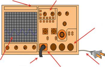
Fig. 4.2 Schematic diagram of EMI
shared by the interference signals of electromagnetic susceptibility due to the reciprocity. In Fig. 4.2, the intentional and unintentional radio frequency energy can be picked up by the system or emitted from the system equally through apertures or slots on the surface of the equipment, power lines, data lines, cable bases, control boxes, control panels, etc.
In addition, we need to distinguish between interference and jamming: The former is used in EMC field; the latter is used in the field of electronic warfare.
4.1.2 Electromagnetic Compatibility
First, we need to distinguish between electromagnetic compatible and electromagnetic compatibility (EMC).
Electromagnetic compatible is a state where all systems, equipment, and devices that work with the electromagnetic spectrum can perform their own functions in common electromagnetic environment.
Electromagnetic compatibility is an ability that enables all systems, equipment, and devices to work with the electromagnetic spectrum. This ability ensures that they will not cause unacceptable or unexpected performance degradation due to electromagnetic emissions or responses under predetermined operating conditions.
The definition of EMC is explained below. There are three points in the definition of EMC that the reader should pay attention to:
64 |
4 Basic Concepts of Quantitative System-Level EMC Design |
(a) |
(b) |
Limit of fadiated emission |
Limit of radiated |
|
|
|
susceptibility |
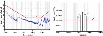
Fig. 4.3 EMC test result of a system. a Limit of electromagnetic emission; b limit of electromagnetic susceptibility
(1)An ability. It emphasizes that EMC, like other functional indicators, is an indicator that electronic information systems must satisfy. That is, if the EMC of an electronic information system fails, the electronic information system is unqualified.
(2)Predetermined operating conditions. It generally includes the external electromagnetic environment where the electronic information system platform operates to perform the intended tasks (mainly affecting the system EMC during normal use) and the electromagnetic environment within the electronic information system platform itself (mainly affecting the electromagnetic compatibility within the system). Therefore, the predetermined operating conditions should be taken as an input for the EMC verification and design. It should also be included in the overall demonstration and design of the electronic information system, which requires to add the EMC requirements analysis, EMC brief design and detailed design into the design of electronic information systems.
(3)Unexpected performance degradation. It emphasizes that there must be a margin in EMC design (margin is a unique requirement of EMC), which is due to the inherent electromagnetic susceptibility and electromagnetic vulnerability (EMV) of electronic information systems.
Based on EMI, EMC sets limits to the electromagnetic emission and electromagnetic susceptibility. Electromagnetic emission has an upper limit, while electromagnetic susceptibility has a lower limit, as shown in Fig. 4.3.
Our readers can get a better understanding of the limit required by regulations for the electromagnetic emission and electromagnetic susceptibility by comparing Fig. 4.1 with Fig. 4.3. These are basic EMC requirements of electronic information systems.