

3555
.pdfRussian Journal of Building Construction and Architecture
Calculating the vectorB(q,q)
Calculating the vectorС(q)
Calculating |
|
Operating |
the vector |
|
mechanism |
I(t) |
|
|
Calculating the matrix A(q)
Fig. 2. Scheme of designing operating efforts
4. Structure of the operating system of the manipulator. A microprocessor system of dynamic operation of the manipulator operating in angular coordinates is designed in compliance with the functional scheme shown in Fig. 3.
OPM |
|
Uзт1 |
CS1 |
M1 |
R1 |
OM1 |
MS1 |
|
|
||||||
|
|
|
|
|
|
|
|
|
|
|
|
|
SS1 |
|
|
|
IIM |
|
|
|
|
||
CMS |
|
Uзтn |
CSn |
Mn |
Pn |
OMn |
MSn |
|
|
||||||
|
|
|
|
|
SSn |
|
|
Fig. 3. Functional scheme of a microprocessor system of dynamic operation of the manipulator
The functional scheme is made up of the following blocks:
––operating calculating machine (OPM);
––connection module with sensors (CMS);
––input/output module (IIM);
––current sources of the robot coordinates (CS1—CSn), n = 1, 2, 3;
50
Issue № 2 (42), 2019 |
ISSN 2542-0526 |
––operating engines (М1—Мn);
––speed sensors (SS1—SSn);
––pressure reducers (R1—Rn);
––operating mechanisms of the robot coordinates (OM1—OMn);
––movement sensors (MS1—MSn).
According to the required track maintenance efforts, there is a range of support points in the movement trajectory of the manipulator. Intermediate coordinates between the support points are calculated as a result of interpolation of the trajectory using cubic splines [5, 6, 10, 14] by means of the sweep method [1] and the resulting interpolation algorithm [15].
Using the module CMS, the OPM gets the information from the sensors MS1—MSn about the position of the coordinates. From the sensors SS1—SSn through the module IIM comes the information about the engine speed. Based on it, the codes of the signals of the current flows of the operating engines are designed.
The module IIM transforms the codes into similar signals Uзт1—Uзтn that come to the current sources CS1—CSn. The winding of the anchors of the operating engines М1—Мn are fed by the specified current providing the processing of the required movements of the coordinates.
Conclusions. 1. In limited metro spaces it is viable to employ three-coordinate manipulators with an angular coordinate system which are extremely compact as they can be folded almost without protruding from the sizes of the robot foundation.
2.As operating efforts on the robot’s handles for laying sleepers are designed, it is advisable to employ the method of dynamic operation where a dynamic model of the manipulator is included immediately into the operating structure of the robot.
3.The new equations of a three-coordinate manipulator with an angular coordinate system obtained using the calculation scheme and the Lagrange method in the differential and vector formprovide operationofthe manipulator inrealtime ifused aspart ofa microprocessor system.
References
1.Bakhvalov N. S. Chislennye metody (analiz, algebra, obyknovennye differentsial'nye uravneniya) [Numerical methods (analysis, algebra, ordinarydifferential equations)]. Moscow, Nauka Publ., 1975. 632 p.
2.Vukobratovich M., Stokich D., Kirchanski N. Neadaptivnoe i adaptivnoe upravlenie manipulyatsionnymi robotami [Non-adaptive and adaptive control of manipulative robots]. Moscow, Mir Publ., 1989. 376 p.
3.Vukobratovich M., Stokich D. Upravlenie manipulyatsionnymi robotami. Teoriya i prilozheniya [Control of manipulative robots. Theoryand applications]. Moscow, Nauka Publ., 1985. 384 p.
4.Krut'ko P. D. Upravlenie ispolnitel'nymi sistemami robotov [Control of Executive systems of robots]. Moscow, Nauka Publ., 1991. 336 p.
51

Russian Journal of Building Construction and Architecture
5.Marchuk G. I. Metody vychislitel'noi matematiki [Methods of computational mathematics]. Moscow, Nauka Publ., 1980. 535 p.
6.Medvedev V. A. Mikroprotsessornaya sistema upravleniya manipulyatorom “PUMA-560” [Microprocessor control system of manipulator “PUMA-560”]. Vestnik Voronezhskogo gosudarstvennogo tekhnicheskogo universiteta, 2017, vol. 13, no. 3, pp. 34—38.
7.MedvedevV. A., Novikov A. A. [Modeling the dynamics of manipulators with arbitrary kinematic structures].
Trudy “Analiz i proektirovanie sredstv robotizatsii i avtomatizatsii” [Proc. “Analysis and design of robotics and
automation equipment”]. Voronezh, Voronezh. gos. tekhn. un-t Publ., 1999, pp. 139—142.
8.Medvedev V. A., Petrenko V. R., Kuzovkin A. V. Modelirovanie ispolnitel'noi sistemy robota PUMA-560 v srede MATLAB [The simulation Executive system of the robot PUMA 560 in MATLAB]. Vestnik Voronezhskogo gosudarstvennogo tekhnicheskogo universiteta, 2011, vol. 7, no. 12—3, pp. 4—6.
9.Medvedev V. A. Modelirovanie robotov i RTS [Simulation of robots and RTS]. Voronezh, Voronezh. gos. tekhn. un-t Publ., 2010. 106 p.
10.Medvedev V. A. [Development and research of the control system of the manipulator “PUMA-560”]. Trudy “Novye tekhnologii v nauchnykh issledovaniyakh, proektirovanii, upravlenii, proizvodstve”[Proc. “New technologies inresearch, design,management,production”]. Voronezh, Voronezh.gos. tekhn. un-t Publ., 2017, pp. 311—315.
11.Medvedev V. A. [Energy-saving robot control system “PM-01”]. Trudy “Al'ternativnaya i intellektual'naya energetika” [Proc. “Alternative and intellectual energy”]. Voronezh, Voronezh. gos. tekhn. un-t Publ., 2018, pp. 252—253.
12.Pavlov V. A., Timofeev A. V. Postroenie i stabilizatsiya programmnykh dvizhenii podvizhnogo robotamanipulya¬to¬ra [Construction and stabilization of programmed movements of a movable robotic manipulator].
Izv. AN SSSR. Tekhnicheskaya kibernetika, 1976, no. 6, pp. 91—101.
13.Pol R. Modelirovanie, planirovanie traektorii i upravlenie dvizheniem robota-manipulyatora [Simulation, trajectoryplanning and motion control of robotic manipulator]. Moscow, Nauka Publ., 1976. 104 p.
14.Popov E. P., Vereshchagin A. F., Zenkevich S. L. Manipulyatsionnye roboty: dinamika i algoritmy [Manipulation robots: dynamicsand algorithms]. Moscow, Nauka Publ., 1978. 400 p.
15.Shiyanov A. I., Medvedev V. A., Semenov A. M., Kalyadin M. R. Konturnoe upravlenie manipulyatorom s uglovoi sistemoi koordinat [Contour control of a manipulator with angular coordinate system]. Elektrichestvo, 1998, no. 5, pp. 40—42.
16.Hollerbach J. M. A Recursive Formulation of Lagrangian Manipulator Dynamics. IEEE Transactions on Systems, Man, and Cybernetics, 1980, vol. 10, no. 11, pp. 730—736.
17.Kahn M. E., Roth B. The Near-Minimum-Time Control of Open-Loop Articulated Kinematic Chains. Journal of Dynamic Systems, Measurement and Control, 1971, no. 93, pp. 164—172.
18.RenaudN. An Efficient Iterative Analytical Procedurefor Obtaining a Robot Manipulator Dynamic Model. Proc. ofFirst International Symposium ofRobotics Research.Bretton Woods, NewHampshire, USA, 1983,pp.749—762.
19.Uicker J. J. Dynamic Force Analysis of Spatial Linkages. Transactions of the ASME Journal of Applied Mechanics, 1976, vol. 34, pp. 418—424.
20.Vukobratovich M., Kircanski N. NewMethod for Real-Time Manipulator Dynamic Model, Forming on Microcomputers. Proc. of First Yugoslav-Soviet Symposium on Applied Robotics. Moscow, 1983, pp. 60—65.
21.Yang A. T. Inertia Force Analysis of Spatial Mechanisms. Transactions of the ASME Journal of Engineering for Industry, February, 1971, pp. 39—46.
52

Issue № 2 (42), 2019 |
ISSN 2542-0526 |
DOI 10.25987/VSTU.2019.42.2.006
UDC 625.7.004:551.58
Т. V. Samodurova1, V. V. Volkov 2, K. A. Sklyarov3
MODELLING THE BEARING PROPERTIES OF A ROAD STRUCTURE
RESTORED USING INTERLAYER INJECTION
BY MEANS OF A REPAIRING SOLUTION
Voronezh State Technical University
Russia, Voronezh
1D. Sc. in Engineering, Prof. of the Dept. of Designing Highways and Bridges, tel.: (473)271-52-02, e-mail: samodurova@vgasu.vrn.ru
2PhD in Engineering, Assoc. Prof. of Construction Mechanics, tel.: 8-910-240-25-87, e-mail: kotlac@yandex.ru
3PhD in Engineering, Assoc. Prof., Dean of the Faculty of Architecture and Technology, tel.: (473)271-59-26, e-mail: stf@vgasu.vrn.ru
Statement of the problem. One of the major elements in the operation of roadway surfacing is current repairs and maintenance. On the surface of a roadway surfacing there are a lot of defects (shelling, pits, potholes, cracks) that need to be timelyremoved. These defects lead to a quick degradation of the operational properties of highways and call for repairs and maintenance. The objective of the research is to compare and study the existing methods involving interlayer injection based on mathematical changes in the bearing properties through the course of repairs.
Results. The comparative analysis of some methods of strengthening of a structure where a defect occurs showed that injection of strengthening solutions into certain layers of the foundation might be effective. The obtained mathematical model of interlayer injection allowed a numerical analysis of strengthening of the foundation with further restoration of the bearing capacity of a defected area. The obtained data indicate that defected moist area with its surfacing that might be further repaired is almost completely restored. The deflections in the repaired area are different from the standards ones by no more than 2—5 %.
Conclusions. The mathematical modeling showed that the use of injection of liquid solutions into the foundation layers in order to strengthen it has a number of advantages: lower destructive impact on the layers of a road structure, formation of areas with lower water permability that allow one to cut short the processes caused by water migration and mineral particles of the foundation, high repairsrates.
Keywords: repairs, highway, artificial foundation, injection of a solution.
Introduction. A variety of roadwau surfacing repairs and maintenance methods requires feasible and economically and technically advantageous solutions allowing for cost-effective superficial repairs as wellas restoration ofthe load-carrying capacityof highway construction layers.
© SamodurovaТ. V., Volkov V. V., Sklyarov K. A., 2019
53

Russian Journal of Building Construction and Architecture
Most of the methods are a sequence of technological procedures to remove surfacing defects [2, 8, 13, 14, 17] with a few of them involving partial restoration of a surfacing layer and some of them designed for reinforcement of each layer using different physical modifications. A loss in strength of a road structure is known to be associated with the load-carrying property of a lower artificial base and foundartion mainly threatened by moisture migration from lower layers and infiltration through defects in surfacing when an increase in the moisture level of the foundation compromises its load-carrying capacity.
Therefore one of the tasks is to develop methods of strenghening an artificial base and foundation during highway repairs. There are some methods [3, 5] employing a mechanical impact on road structure layers with a mechanical applicator injected into the centre of a defected area which is submerged at a required depth under vibration or small rotations, i.e. discompacted layers are further compacted as a result of a mechanical impact. Being obviously simple, one of the major drawbacks is the same mechanical impact which while compacting material next to an applicator causes shear stress leading to cracking. In Japan, Australia superficial compactors for defected surfaces are employed with a vertical vibrating stamp that is constantly submerged installed in a defected area [10, 16, 18]. As a result of this mechanical impact upper layers shift down increasing the load-carrying capacity and decreasing the porosity of construction materials. One of the drawbacks is that it is impossible to use it on intensely moisturized base courses as well as resulting mixing of the structure of the layers, which might ultimately compromise the performance and durability of this particular highway area. In some countries [15] a defect area is cut with a large-diameter boring head at the depth of 1 or 2 meters and then filled as roadway construction layers are compacted. This method is capable of completely removing all physical and chemical processes of highway construction deterioration but it is extremely complex and costly and requiresthe same materials that have been used for highway construction.
Methods of strengthening an artificial base and foundation by means of injecting strengthening solutions and suspensions into it are worth a separate discussion [1, 4, 9, 11, 12]. They are grouped into methods of vertical and horinzontal introduction of strengthening solutions under pressure. Horizontal methods proved to be efficient for large construction areas such as railways, poor base course roads, areas with great moisture migration and circulation [6, 7]. As efficient as this method is, it is not good for repairing individual small areas and thus vertical injection is recommended to be used for obtaining materials in underlying layerswith higher strengthproperties. The objective of the study is to compare and investigate existing methods of underlying injection and using mathematical modeling to identify changes in the load-carrying properties during repairs.
54
Issue № 2 (42), 2019 |
ISSN 2542-0526 |
1. Mathematical statement of the task of injecting strengthening solutions into road con-
struction layers. In order to model strengthening of an artificial base and subgrade, it is necessary to consider some effective material describing their properties. For that let us assume that a soil is a set of spherical particles with a solution strengthened between them as part of injection. Resulting pores in the form of a transverse section of a channel were investigated by Slichter [1] who pointed out that even when balls are closely positioned (Θ = 600) both narrowing and expansion are likely, which causes the particles to repack and thus the material density to change. The liquid coming through a surface defect has the speed W0 that is proportionate to the porosity n:
(1) The filtration rate through an ideal soil can be expressed using the porosity but the permeabilitycoefficient k that has the dimensionality
W |
k P1 P2 |
|
|
||||
|
|
|
|
|
, |
(2) |
|
|
l |
|
|||||
|
|
|
|
|
|||
Kф |
k |
|
, |
|
|
(3) |
|
|
|
|
|||||
|
|
|
|
|
|
|
|
where τ is the index depending on the liquid flow mode; (P1 – P2) is a drop in the hydrodynamic pressure; l is the length of the porous channel; μ is the absolute viscosity; δ is the hydraulic radius that is the ratio of the area of the transverse section of the channel n to the perimeter χ.
The filtration coefficient of the soil is connected to its permeabilitywith the solution by means ofthe ratio
K k |
|
, |
|
(4) |
|
|
|||||
ф |
|
|
|
||
where is the density of the solution. |
|
|
|
|
|
The filtration rate [18] will be given by the expression |
|
||||
W1 mW0, |
(5) |
||||
where m is the gap for spherical particles in the soil that is given by the expression |
|
||||
m 1 |
|
, |
|
||
|
|
||||
|
4sinΘ |
|
|||
where Θ is the angle of the rhomb that makes up the faces of the rhombohedron and changes from Θ = 900 to Θ = 600.
55
Russian Journal of Building Construction and Architecture
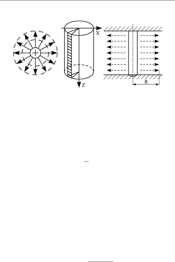
Vertical injection can be regarded as a flat and radial task [1] (Fig. 1).
Fig. 1. Presentation of the distribution of the injected solution during vertical injection in flat layers
(a simple radial task)
Movement of the injected solution can be regarded as the distribution of the liquid between the restraining layer of the surface and more compacted underlying layers. It should be noted that the pressure of the injected liquid should generate its distribution area that is larger than a defect in an asphalt concrete surface.
In case the ratio of the length of the perforated part L to the diameter of the injector is
L
Dн D 5,
which is typical of the beginning of cracking, the radius-time dependence is given by the same formula:
|
|
|
2 2 |
|
1 |
|
|
||
|
|
|
ln |
|
|
|
1 |
|
|
|
|
2 |
|
||||||
f |
|
|
|
|
|
|
. |
(6) |
|
|
|
|
|
||||||
|
|
4 |
|
|
|
||||
|
R |
|
|
|
|
|
|
||
|
|
|
|
|
|
|
|
|
|
Given that poorly viscous solutions where χ > 10 are used for injection, the expression takes the following form:
f R |
2 ln2 1 |
|
||
|
. |
(7) |
||
4 |
||||
|
|
|
||
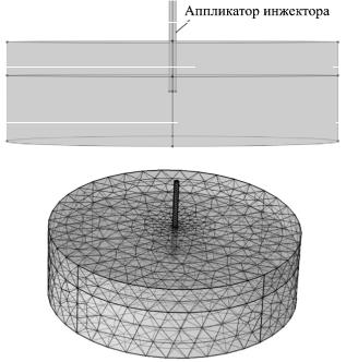
Modelling the spherical task (Fig. 2) and considering the pumping of the solution through an injector with an open end, we get
f 2 3 3 2 1) . (8)
c |
6 |
|
56
Issue № 2 (42), 2019 |
ISSN 2542-0526 |
а) |
Injector applicator |
Sand
Subgrade
b)
Fig. 2. Calculation scheme of pumping of the injection solution into the infiltrating soil:
а) calculation scheme of radial pumping; b) net model
The major characteristics of the layer materials are taken from the guideline ODN (ОДН) 218.046-01 “Designing Non-Rigid Roadway Surfacing” and ODM (ОДМ) “Regulations on Soils and Materials Reinforced with Organic Binders”.
According to the modeling, using a controlled injector one can vary the speed of the solution injection into each layer. Thus the task involves a radial and parallel one with sphereical sources. Then the amount of the solution through the injector to the radial and spherical area is QΣ = QR + QC.
Therefore flowing of the solution QΣ from the injector results in porous filling both of the cylindrical and semispherical areas with each of them filling over the time t.
A longer time for the spherical area tC > tR allows the layers to be saturated with no gravitational infiltration and the radius of the solution distribution to be identified.
The time parametersthat are necwssaryfor the solution injectioncan be identified using the above rations, technologicalparametersand characteristics ofthe soil:
f |
tKф P1 P2 |
|
|
|
|
|
r, |
(9) |
|
nr2 |
|
|||
|
|
|
|
|
0 |
|
|
|
|
where t is the time of filling of the semispherical area; r0 is the radius of the injector; (P1 – P2) is a drop in the hydrodynamic pressure; Kф is the coefficient of the soil filtration.
57
Russian Journal of Building Construction and Architecture
The obtained expression allows the difference of pressure in the injector applicator and at the end of the solution distribution to be determined.
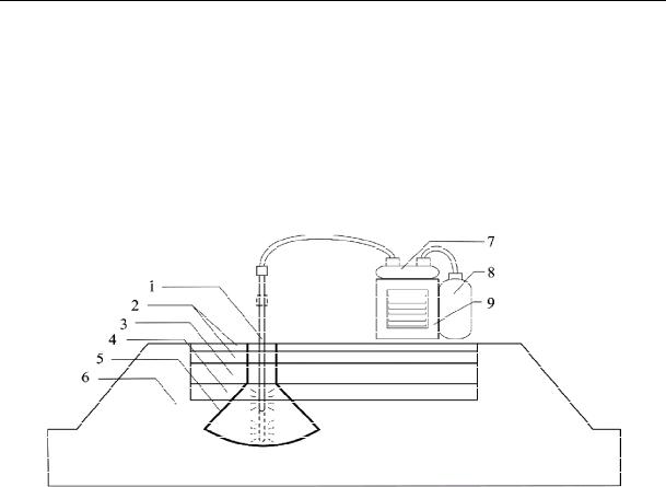
2. Results of modeling the load-carrying properties of a road structure. In order to assess the technical effect of the injection of an artificial base and subgrade, let us look at a technological setup in Fig. 3. It is designed for vertical injection of solutions used in road structure repairs.
Fig. 3. Technological setup for injection of solutions into an artificial base and subgrade: 1 is a liquid injection applicator; 2 is the upper and lower layer of an asphalt concrete surface; 3 is a limestone foundation layer; 4 is a sandyunderlying layer;
5 is a defect area with an excessivelymoisturized cone (repairs area); 6 is a subgrade;
7 is a receiving pumper; 8 is a tank with a repair solution used for injection; 9 is a compressor
In order to evaluate possible changes in the load-carrying capacity of the construction layers, it is necessary to identify the radius and depth of injection. Due to a varying granulometric composition during the movement of the solution into a porous environment a resulting area can be viewed as a volume of the reinforced structure which is a geometric figure consisting of cylinders, semispheres and semiellipsoids [1]:
V V |
V |
V |
2 |
R3 |
R2h |
|
|
R2h |
|
2 |
R3 |
R2 1,3R h |
h |
; (10) |
|
|
|
|
|||||||||||||
в |
1 |
2 |
3 |
3 |
|
2 |
|
4 |
|
3 |
|
2 |
4 |
|
|
|
|
|
|
|
|
|
|
|
|
|
|
|
|
||
(11) where V1 is the volume of the semisphere; V2 is the volume of the cylinder; V3 is the volume of the semiellipsoid.
A feature of the figure is that the lower part of the volume is a semisphere shifted vertically down at the distance of h4 from the end of the perforated area of the injector.
58
Issue № 2 (42), 2019 |
ISSN 2542-0526 |
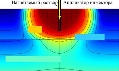
Fig. 4 shows the distribution of the injected repairing solution in the body of the underlying layer and subgrade base. The injector of the repairing solution coming through the applicator causes movement and absorption of the liquid inside the base course. If the viscosity of the solution is optimal, it is distributed in the injected layer hardly penetrating the neighbouring one. This enables the injection into the layers to be specified and the required strength of the layer to be obtained.
Pumped solution |
|
Injector applicator |
Sand
Layer interface
Subgrade base
Fig. 4. Distribution of the injected repairing solution in the body of the sandyunderlying layer and subgrade base
Solving the task in relation to (9) and considering that the viscosity of the solution (4) has a strong effect on the permeability rate of the solution between the particles, the volumes filled with the injected solution were calculated. The strength acquired by the composite was assumed to be a component of the total elasticity modulus and then the values were obtained for each layer. Fig. 5 shows the graphs of the acquired material strength of the base and subgrade on the volume of the repairing solution for different viscosity values.
The analysis of the resulting data showed that for each soil type repairing solutions with optimal viscosity levels should be selected. By changing the viscosity properties of injected mixes, their consumption as well as the overall strength characteristics of a structure can be controlled.
The suggested method of injecting binding solutions offers several advantages as opposed to the mixing methods, namely it reduces the number of technological operations, which is likely to contribute to the productivity of a construction flow and result in a material with higher strength characteristics due to a more effective distribution of a solution in soil pores during injection.
59