

3395
.pdfRussian Journal of Building Construction and Architecture
whose integration in the substitution y = hcosΘ gives an equation of the family of cycloids, for which the derivative (17) is always positive, therefore, it is necessary to consider only the part where y increases as does x:
y = h cos Θ, |
|
|
|
(18) |
|
x = −h(Θ + sin Θ ) + A. |
||
|
||
|
|
|
|
|
Similarly, the second system of slip lines defined by the equation (16) yields the cycloids:
y = h cos Θ, |
|
|
|
(19) |
|
x = h(Θ − sin Θ) + B, |
||
|
||
|
|
|
|
|
for which the sections where y decreases should be considered. The arbitrary constants A and B must be identified based on the boundary conditions.
2. Calculation of the rates of stress and deformation. For the purpose of physical interpretation of the results, let us consider a part of the medium deformed according to the scheme in Fig. 1 and bounded by the lines x = 0, x = l, y = ± h (Fig. 3).
Fig. 3. Scheme of the distribution of the slip lines and normal stresses in the deformed environment between the rough plates. 1 is a family of slip lines (18); 2 is a family of slip lines (19)
Obviously, the planes y = ± h will be under the stresses (13) where the constant P is found using the boundary condition:
σ |
y |
|
|
= 0 = −P + kl |
, |
|
|
||||
|
|
x=l |
h |
|
|
|
|
|
hence
P = klh .
60

Issue № 3 (47), 2020 |
ISSN 2542-0526 |
Then the expression (13) is as follows:
|
|
|
|
σy |
= k |
(x − l). |
|
|
|
|
|
|
(20) |
|||||
|
|
|
|
|
|
|
|
|
h |
|
|
|
|
|
|
|
|
|
In the planes x = 0 and x = 1 there are the following stresses |
|
|||||||||||||||||
σ |
|
|
|
|
|
|
= |
kl |
+ 2k 1 |
− |
|
y |
2 |
, |
(21) |
|||
x |
|
|
|
|
|
|
||||||||||||
|
x=0 |
h |
|
h |
2 |
|||||||||||||
|
|
|
|
|
|
|
|
|
|
|
||||||||
|
|
|
|
|
|
|
|
|
|
|
|
|
|
|
|
|
||
|
σ |
x |
|
|
|
|
= 2k 1− |
y2 |
, |
|
|
(22) |
||||||
|
|
|
|
|
|
|
||||||||||||
|
|
x=l |
|
h |
2 |
|
|
|||||||||||
|
|
|
|
|
|
|
|
|
|
|
|
|
||||||
|
|
|
|
|
|
|
|
|
|
|
|
|
|
|
|
|
||
whose directions of action and their qualitative distribution are presented in Fig. 3. It can be seen that there is a linear decrease in the stresses σy from the center to the periphery of the compressing plates and a power-law dependence of σx over the thickness of the deformed layer ensuring the movement of the material to the right. The same figure schematically shows families of orthogonal slip lines which are cycloids in accordance with the equations (18) and (19).
In order to find the distribution of the strain rates of the corresponding stresses (6), (12), (13), we use the dependences between stress and strain, which for the case of an absolutely incompressible body within the framework of plane strain [1, 16, 18] are
Sx = 2φ |
∂vx |
, |
|
|
(23) |
|||
|
|
|
|
|||||
|
|
∂x |
|
|
|
|
|
|
Sy = 2φ |
∂vy |
, |
|
|
(24) |
|||
|
|
|
||||||
|
|
∂y |
|
|
|
|
|
|
|
∂v |
|
∂vy |
|
(25) |
|||
τxy = φ |
|
x + |
|
|
|
|
, |
|
|
|
|
∂x |
|||||
|
∂y |
|
|
|
|
|
||
where vx and vy are the components of the loading speed; φ is an unknown function containing the strain rate; Sx and Sy are the components of the stress deviator which for the case of coincidence of the main axes of the strain rate with the main axes of the stress deviator and the previously introduced designations are
S |
|
= k |
1− |
|
y2 |
|
, |
|
(26) |
|||||||
x |
h2 |
|
|
|||||||||||||
|
|
|
|
|
|
|
|
|
|
|||||||
S |
|
= −k |
1− |
|
|
y |
2 |
. |
(27) |
|||||||
y |
|
h2 |
||||||||||||||
|
|
|
|
|
|
|
|
|
|
|||||||
As a value is chosen, |
|
|
|
|
|
|
|
|
|
|
|
|
|
|
|
|
|
|
|
|
k 1− |
y2 |
|
|
|
|
|
|
|
||||
φ = |
|
h2 |
|
|
, |
|
(28) |
|||||||||
|
|
|
|
|
||||||||||||
|
|
2u |
|
|
|
|||||||||||
|
|
|
|
|
|
|
|
|
|
|
|
|
|
|
|
|
61

Russian Journal of Building Construction and Architecture
the equation (24) is satisfied by the solution
vx = − |
y |
u, |
(29) |
|
|||
|
h |
|
|
which corresponds to the approximation of the planes with the velocity u. Inserting a similar value into (23), we get
vx = ux |
+ ξ(y), |
(30) |
h |
|
|
where ξ(y) is determined based on the condition that vx and vy satisfy (25). For that it is necessary that
d [ξ( y)] = − |
|
2uydy |
, |
||||||||
h h2 − y2 |
|||||||||||
hence |
|
|
|
|
|
|
|
|
|
|
|
|
|
ξ( y) = 2u |
1− |
|
y2 |
, |
|
||||
|
|
h2 |
|
||||||||
|
|
|
|
|
|
|
|
|
|
||
and the expression (30) for the velocity is |
|
|
|
|
|
|
|
|
|||
v |
x |
= |
ux |
+ 2u |
1− |
|
y2 |
|
. |
(31) |
|
h |
|
h2 |
|
||||||||
|
|
|
|
|
|
|
|
|
|||
It can be seen that the velocity components (29) and (31) satisfy the required conditions and correspond to the plastic material, which is squeezed to the right during flat pressing and the velocity (31) at the exit from the plates is
v |
x |
|
|
= ul . |
(32) |
|
|
||||
|
|
x=l |
h |
|
|
|
|
|
|||
|
|
|
|
|
It should be noted that the obtained velocity components vx and vy are proportional to the speed of approach of the plates, while their corresponding stresses do not depend on the loading rate. This is contradictory to the conclusions of the problem [10] which employs the model of a viscous fluid. Additionally, the effect of slipping of the deformable medium on the rough surfaces of the pressing plates and the satisfaction of the boundary conditions τxy = ± k at y = h means [5, 17] the equilibrium of the friction forces and pressing pressure per unit length of the deforming plates, i.e.,
l |
σ y dx = kl |
, |
(33) |
0 |
μ |
|
|
where μ is the coefficient of the sliding friction between the surface of the plate and the pressed medium whose the value makes it possible to vary the composition and moisture content of the composite.
62
Issue № 3 (47), 2020 |
ISSN 2542-0526 |
The analysis of the results of the presented study allows the following conclusions to be drawn.
Conclusions
1.A physical and mathematical model has been set forth which describes the properties of the material in the process of direct pressing of the composite within the framework of plane deformation and the principles of ideal plasticity.
2.The parameters of the stress-strain are obtained under the assumption of a quasi-static pressing process making it possible to obtain the distribution of normal stresses over the thickness and plane of the deformed layer. The stresses in the direction of approaching the plates were found to decrease linearly from the center to the periphery and not to depend on the deformation rate.
3.If negative values for σx in (12) are used, for the practical use of this solution one should remember the state when the deformable material will be injected through the section x = l forcing the compressive planes outward and away from each other.
4.The kinematic characteristics of the pressing process were obtained: the components of the deformation rate which are tangent at each point of the slip lines and their value is proportional to the speed of convergence of the plates.
5.For the resulting theoretical calculations to be practically employed for investigating the stress-strain of a composite material, it is necessary to conduct experiments to identify the coefficient of sliding friction between the surface of the slab and the deformable medium to be able to control the processes of compression and spreading of the layer.
References
1.Aleksandrov S. E., Baranova I. D., Mishuris G. Szhatie vyazkoplasticheskogo sloya mezhdu sherokhovatymi parallel'nymi plitami [Compression of the viscoplastic layer between rough parallel plates]. Izv. RAN. MTT, 2008, no. 6, pp. 33—39.
2.Aleksandrov S. E., Lyamina E. A., Tuan N. M. Obobshchenie zadachi Grandtlya na modeli polzuchesti [Generalization of the Prandtl problem to the creep model]. Prikladnaya mekhanika i tekhnicheskaya fizika, 2014, vol. 55, no. 4, pp. 152—159.
3.Antsiferov V. N., Perel'man V. E. Mekhanika protsessov pressovaniya poroshkovykh i kompozitsionnykh materialov
[Mechanics of pressing processes for powder and composite materials]. Moscow, Graal' Publ., 2001. 631 p.
4.Belov N. A., Kadymov V. A. Analiz kraevoi zadachi techeniya plasticheskogo sloya mezhdu sblizhayushchimisya zhestkimi plitami [Analysis of the boundary value problem of plastic layer flow between converging rigid plates]. Izv. RAN. MTT, 2011, no. 1, pp. 46—58.
63

Russian Journal of Building Construction and Architecture
5.Georgievskii D. V., Yushutin V. S. Kvazistaticheskoe szhatie i rastekanie asimptoticheski tonkogo nelineinovyazkoplasticheskogo sloya [Quasi-static compression and spreading of an asymptotically thin nonlinear viscoplastic layer]. Prikladnaya mekhanika i tekhnicheskaya fizika, 2012, vol. 53, no. 3, pp. 150—157.
6.Dornyak O. R. Matematicheskoe modelirovanie protsessa pressovaniya drevesiny v razlichnykh napravleniyakh mekhanicheskoi anizotropii [Mathematical modeling of the wood pressing process in various directions of mechanical anisotropy]. Izvestiya vuzov. Severo-Kavkazskii region. Tekhnicheskie nauki, 2005, Spets. vypusk «Kompozitsionnye materialy», pp. 85—92.
7.Ishlinskii A. Yu., Ivlev D. D. Matematicheskaya teoriya plastichnosti [Mathematical theory of plasticity]. Moscow, Fizmatgiz Publ., 2001. 704 p.
8.Kozlov G. V., Zaikov G. E., Stoyanov O. V., Kochnev A. M. Dispersno-napolnennye polimernye nanokompozity [Dispersed-filled polymer nanocomposites]. Kazan, KNITU Publ., 2012. 125 p.
9.Kotenko V. D., Rudenko B. D., Izotov V. D. Modelirovanie svoistv i protsessov pressovaniya reaktoplastov
[Modeling of the properties and processes of pressing thermosetting plastics]. Moscow, GOU VPO MGUL Publ., 2005. 284 p.
10.Kumitskii B. M., Savrasova N. A., Kantieva E. V. Matematicheskoe modelirovanie protsessa skleivaniya drevesnogo shpona v usloviyakh ploskogo pressovaniya fanery [Mathematical modeling of wood veneer bonding under flat plywood pressing conditions]. Lesotekhnicheskii zhurnal, 2018, vol. 8, no. 2 (30), pp. 204—212.
11.Lesovik V. S., Pogorelov S. A., Strokova V. V. Gipsovye vyazhushchie materialy i izdeliya [Gypsum binders and products]. Belgorod, 2000. 224 p.
12.Mirsaev R. N., Babkov V. V., Yunusova S. S., Kuznetsov L. K., Nedoseko I. V., Gabitov A. I. Fosfogipsovye otkhody khimicheskoi promyshlennosti v proizvodstve stenovykh izdelii [Phosphogypsum waste from the chemical industry in the production of wall products]. Moscow, Khimiya Publ., 2004. 176 p.
13.Petrov A. G. Razvitie techeniya vyazkoi i vyazkoplasticheskoi sredy mezhdu dvumya parallel'nymi plastinami [Development of the flow of a viscous and viscoplastic medium between two parallel plates]. Prikl. matematika i mekhanika, 2000, vol. 64, iss. 1, pp. 127—136.
14.Plotnikov N. P., Plotnikova G. P. Sovershenstvovanie tekhnologii proizvodstva drevesnoplitnykh materialov [Improving the technology of production of wood-based materials]. Novosibirsk, NP «SibAK», 2013. 112 p.
15.Savrasova N. A., Agapov A. D., Kumitskii B. M. Matematicheskoe modelirovanie ploskogo pressovaniya sloistykh plastikov [Mathematical modeling of flat pressing of layered plastics]. Sovremennye problemy teorii mashin. Novokuznetsk, Izd-vo NITsMS, 2018, pp. 50––55.
16.Rudskoi A. I., Rybin Yu. I., Tsemenko V. N. Teoriya i modelirovanie protsessov deformirovaniya poroshkovykh i poristykh materialov [Theory and modeling of deformation processes of powder and porous materials]. Sankt-Peterburg, Nauka Publ., 2012. 414 p.
17.Zhu H., Kim Y. D., Kee D. D. Non-Newtonian fluids with stress. Journal of Non-Newtonian Fluid Mechanics, 2005, vol. 129, no. 3, pp. 177—181.
18.Alexandrov S., Mishuris G., Miszuris W. An analysis of the plane-strain compression of a three layer strip. Arch. Appl. Mech, 2001, vol. 71, no. 8, pp. 555—566.
64

Issue № 3 (47), 2020 |
ISSN 2542-0526 |
BUILDING MECHANICS
DOI 10.36622/VSTU.2020.47.3.006
UDC 624.072.336.2
M. N. Kirsanov1
ANALYTICAL CALCULATION OF THE DEFLECTION
OF A SPATIAL HINGE-ROD FRAME WITH AN ARBITRARY NUMBER OF PANELS
National Research University “Moscow Power Engineering University”1
Russia, Moscow
D. Sc. in Physics and Mathematics, Prof. of the Dept. of Robotics, Mechatronics, Dynamics and Strength of Machinery, tel.: (495)362-73-14, e-mail: c216@ya.ru
Statement of the problem. The task is to obtain in symbolic form the dependence of the deflection of the proposed scheme of a statically definable spatial truss of a regular type on the number of panels under various loads, including the load from the truss plane. A truss has two independent parameters that define its proportions.
Results. For several types of loading according to the Maxwell - Mohr formula, analytical dependences of the deflections of the structure on the number of panels, load, and dimensions are derived. When generalizing a series of partial solutions with a given number of panels to an arbitrary number of panels, together with operators of the Maple computer mathematics system, the induction method is used. Asymptotic approximations of solutions are obtained.
Conclusions. The proposed model of a spatial frame with two independent numbers of panels that define the proportions of the structure allows an analytical solution of the problem of deflection under different types of loading. The derived formulas can be used as test formulas for evaluating approximate numerical solutions and for optimization problems.
Keywords: spatial frame, deflection, double induction, asymptotics, Maple, analytical solution.
Introduction. Trusses offer a plethora of advantages over monolithic or sheet metal elements in building structures. Girder, arched and frame trusses are most commonly used as loadbearing structures. If the structure itself and the load can be decomposed into separate independent plane problems, the calculation of a spatial structure is considered in terms of the operation of the entire structure. Calculations of spatial trusses are commonly conducted in wellknown numerical packages using the finite element method [11, 12, 15, 19, 20, 22, 23]. An alternative line of research into the operation of structures is developing analytical methods. Unlike the numerical ones, analytical solutions have such an advantage that they can
© Kirsanov M. N., 2020
65

Russian Journal of Building Construction and Architecture
be described by means of methods of analysis (e.g., for extremum points, for identifying asymptotes, jumps and inflection points). Nevertheless this applies only to those solutions that are applicable to a wide range of problems. If as a result of fairly complex work with analytical transformations in symbolic mathematics packages (Maple, Mathematica, Maxima, Derive, etc.), a solution is obtained that is applicable to a specific design and a specific load, the effort made is not justified. In this case, the numerical method yields all the basic values for evaluating a structure: deflection, distribution of forces in the rods and forces in critical rods. The more parameters are included in the calculation formula, the more efficient it actually is. The first fairly general formulas for calculating trusses, containing as parameters not only the dimensions and magnitude of the load, but also such an ordinal characteristic of regular systems as the number of panels were designed in the middle of the last century. The formula by Kachurin [6] is known, a number of formulas by Ignatiev [1, 2], algorithm for deriving analy-tical solutions for rod flat and spatial structures by Rybakov, including complex statically indeterminate [7, 8].
The relevance of designing a formula for dependence of the deflection of a spatial structure on the number of panels lies both in the need to have simple and reliable test solutions for the calculation and design of structures for evaluating the results obtained in numerical packages, and for comparing various options of schemes taking into consideration in the design process. Flat truss models do not allow analysis of the operation of a structure under the action of a load from its plane, e.g., a wind load. Therefore in this study a design scheme is proposed and considered which takes the work of the connections into account.
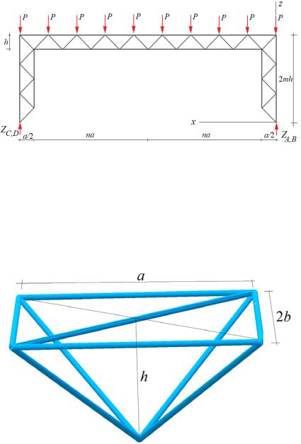
1. Frame design. The rectangular trussed frame has m panels in height and 2n panels in the crossbar (Fig. 1, 2). The length of the panel in the crossbar is a, the height is h, and the width is 2b. Let us place the structure in the coordinate system with the origin at the support A.
Fig. 1. Girder at n = 5, m = 4 : supports: A is a spherical cylinder, B is a cylindrical one, C and D are columns
66
Issue № 3 (47), 2020 |
ISSN 2542-0526 |
Fig. 2. Projection on the plane x-z. |
The girder under the action of an evenly distributed load at n = 4, m = 3 : |
P is a load, h, a are the sizes, |
ZA , ZB , ZC , ZD are vertical components of the support reactions |
The elements of the girder are bar pyramids with a base a × 2b (Fig. 3) connected by additional longitudinal horizontal ties (bars of length a) along the tops.
Fig. 3. Rod element of the crossbar element (panel): a is the length of the panel, 2b is the width, h is the height
Similar pyramids with the bases 2h × 2b make up the symmetrically located lateral trusses with the height of 2mh.
The truss supports are a spherical hinge A, a cylindrical hinge B, and two posts at the angles C and D. There are in total ns = 18(n + m) + 3 bars in the truss excluding the support ones.
The static indeterminacy caused by one extra support rod (support leg D) can be opened simply by replacing this rod with an external force found from the equilibrium condition of the entire system. With a load evenly distributed over 4(n + 1) nodes of the upper chord using the symmetry of the load and the structure, an effort is obtained. Therefore with this replacement
67

Russian Journal of Building Construction and Architecture
taken into consideration, the construction is definable. All rods are assumed to be elastic and the hinges perfect.
The calculation of the deflection of the truss under the action of the load is performed based on the Maxwell-Mohr formula. The efforts in the rods are identified in symbolic form using the software [3] developed in the Maple computer mathematics system both for calculating plane [9, 10, 13, 14, 18, 24] and spatial [4, 5] statically definable trusses. The coordinates of the nodes of the truss are entered into the software. All the nodes (hinge joints of bars) are numbered (Fig. 4). E.g., the coordinates of the nodes of the reference trusses are as follows:
xi = 0, yi = 0, zi = 2h(i − 1), k = 2n + 1,
xi+m+k +1 = 2ak, yi+m+k +1 = 0, zi+m+k +1 = H − 2hi,
xi+2m+k +1 = 0, yi+2m+k +1 |
= 2b, zi+2m+k +1 = 2h(i − 1), |
|
xi+3m+2k +2 = 2ak, yi+3m+ |
2k+2 = 2b, zi+3m+2k +2 = H − 2hi, i =1,..., m. |
(1) |
m1 = 2m + k + 1,
xi+2m1 = a, yi+2m1 = b, zi+2m1 = h(2i −1),
xi+5m+6n+4 = 0, yi+5m+6n+4 = b, zi+5m+6n+4 = h(2m − 2i − a), i = 1,..., m − 1.
Fig. 4. Coordinate axes x, y, z, girder sizes a, b, h, numbering of the rods and nodes at n = m = 2
The structure of a truss is identified according to the order in which the members are connected. For that vectors are introduced with the numbers of the bars and components equaling those of the ends. The members of the truss outer contours, e.g., are defined according to the following vectors:
Vi = [i,i + 1], Vi+k +2m = [i + m1,i + m1 + 1], i = 1,...,m1 −1.
68

Issue № 3 (47), 2020 |
ISSN 2542-0526 |
2. Solution. Vertical load. For the efforts in the truss rods, a system of equations for all nodes is designed. For each node in the system, three equations are assigned in projection, respectively, on the x, y, z axis. The matrix G of the system includes the direction cosines of the forces calculated using the coordinates of a three-dimensional grid of nodes according to the data of the vectors Vi , i = 1,..., ns + 6 including six vectors modeling the supports. The load data is entered on the right side of the system. Under uniform loading of the nodes of the upper girder belt (Fig. 4), the vector of free members has the form B3i = P, B3(i+ m1 ) = P, i = m + 1,.., m + k + 1. The other components of this vector are zero. View components should contain projections of external forces applied to node i in projection onto the axis x, in the components B3i−1on the axis y. The efforts are determined using the solution. In the Maple system, the solution to a system of linear equations written in matrix form is most conveniently searched for by means of the inverse matrix method. In Maple it looks identical as when working with numbers. Here is the corresponding fragment of the program: G1:=1/G: S:=G1. Here G1 is the inverse matrix, S is the vector of unknown efforts, B is the vector of the right sides of the system of equations. The dot in Maple denotes matrix multiplication or matrix-vector multiplication.
The deflection of the truss (the vertical displacement of the middle hinge in the lower girder chord) is identified by means of the Maxwell-Mohr formula
ns |
|
|
|
= N j N |
jl j / (EF) , |
(2) |
|
j=1 |
|
||
where N j is the effort in the j-th bar of the truss from the applied load, N j is the force in the same bar from a single vertical dimensionless force, l j is the length of the bar, EF is the stif-fness of
the rods. Let us consider the case of a uniformly distributed load of vertical forces P distributed over the nodes of the upper belt at h=a. Sequentially calculating the trusses for m = 1 and n = 1, 2, 3, ... , we see that the form of the solution does not depend on the number of panels:
|
A |
a3 + C |
c3 |
+ H |
n,m |
b3 |
|
|
= P |
n,m |
n,m |
|
|
|
, |
(3) |
|
|
EFh2 |
|
|
|
||||
|
|
|
|
|
|
|
||
where c = a2 + b2 + h2 and the coefficients for cubes of sizes form sequences whose common terms can be found using the Maple system operators. The coefficients An,m at a3 for
m=1 have the following numerical sequence: 28, 198, 752,2050,4572, .... The rgf_findrecur operator identifies the recurrence equation that these numbers satisfy:
An,1 = 5An−1,1 − 10An−2,1 + 10An−3,1 − 5An−4,1 + An−5,1. |
(4) |
69