

3395
.pdfRussian Journal of Building Construction and Architecture
where ϕпр (σ і ,εі ) is a parameter that considers the projection of the diagram on the direction perpendicular to the plane k (Fig. 1); ϕα is a parameter that considers the projection of the stress components in the k plane onto the I-I plane, perpendicular to the longitudinal axis of the reinforced concrete element; ϕ y,1 (xb, x) is a parameter equal to the parameter up to a nu-
merical coefficient.
Based on the equilibrium equation of the moments of internal and external forces acting in section I-I relative to the axis perpendicular to this section and passing through the point of application of the resultant forces in the compressed zone (Tb,I = 0), we get:
2 |
0.5τ |
T |
b |
|
2 |
b |
x − T = 0, |
(3) |
|
|
2 |
|
3 |
2 |
|
|
where τТ is shear torsional stress in compressed concrete determined by projecting the diagram σі
– εіon the plane τ – γ and on the plane I – I and distributed proportionally to the ratio Q:T. Based on this equation, we determine the unknown T (for the first group of limit states) and if T is specified through the ratio Rsup:T and when considering the second group of limit states, this equation is used to determineτ T .
The following condition is checked:
τT ≤ τT , pl , |
(4) |
where τ T , pl is shear torsional stress in compressed concrete (considering the ratio Q:T) cor-
responding to the maximum on the σі – εі diagram. If the condition (4) is not met, then τT is assumed to be equal to τT,pl and from the transformed equation (3), the parameter ypl (Fig. 1):
2 [τ T,pl ypl (b / 2 − 0.5ypl )+ 0.5τT , pl (b / 2 − ypl )2 / 3(b / 2 − ypl )] x − T = 0 . |
(5) |
|
Based on the hypothesis of proportionality of the mean longitudinal deformations, we find |
|
|
σ s,I = σ b Es (λ ) h0 |
− x . + σ 0 , |
(6) |
Eb (λ ) |
x |
|
where σ 0 is prestressing in the stressed reinforcement at the moment when the prestressing value in concrete is reduced to zero by the external forces acting on the structure considering prestressing losses in prestressing reinforcement, corresponding to the considered stage of the operation
of the structure. |
|
In this case, it is necessary to check the condition: |
|
σs,I ≤ Rs . |
(7) |
10

Issue № 3 (47), 2020 |
ISSN 2542-0526 |
If the condition (7) is not met,σ s,i is assumed to equal Rs.
The second support block is separated from the reinforced concrete element by a spatial section formed by a spiral crack and a vertical section passing through the compressed concrete zone through the end of the spatial crack front. The balance of this block is ensured by satisfying the following conditions. The sum of the moments of all the internal and external forces acting in the vertical longitudinal plane relative to the z axis passing through the point of application of the resultant forces in the compressed zone is equal to zero (∑Mb=0, block II):
σ smAs (h0 − 0.5xb ) − M − Rsup am,b = 0 , |
(8) |
where аm,b is the horizontal distance from the support to the center of gravity of the compressed concrete zone in section k.
It should be noted that in this equation the moments qsw,T
the longitudinal forces in the transverse reinforcement are mutually balanced relative to the point B. The same should be attributed to the moments caused by the “dowel” components in the longitudinal reinforcement [11]. The unknown σs is given by the equation (8).
Here it is also necessary to point out the parameter σb (the stress in compressed concrete of section k, Fig. 1). This parameter is given by the equation of equilibrium of the moments of internal and external forces in the spatial section with respect to the z axis relative to the point ОК of application of the resultant forces (section k, Fig. 1) in compressed concrete (∑MО,К = 0); we get:
σ b Ab (h0 − 0.5xb ) − M − Rsup am,S = 0 , |
(9) |
where аm,S is the horizontal distance from the support to the center of gravity of all longitudinal reinforcement in section k. The unknown σb is given by the equation (9).
The sum of the projections of all forces acting in a spatial section on the x axis is zero (∑X = 0, block II):
σ φ |
(σ |
,ε |
) φ (c) x |
c2 + b2 − σ |
mA − 2q |
2sw |
(h − x )2 |
+ c2 |
= 0 , (10) |
||
b пр |
i |
i |
α |
b |
|
s s |
0 |
b |
|
|
|
where φα (c) is a parameter equal to the parameter up to a numerical coefficientφα ; q2sw is the linear “dowel” force in the clamps [11], which occurs on the lateral faces of the reinforced concrete element (not shown in Fig. 1). The unknown xb is given by the equation (10).
The sum of the projections of all the forces acting in the spatial section on the y-axis is zero (∑Y = 0, block II):
−τ |
Q |
|
b2 + c2 x − 2q |
sw,Q |
(h − x )2 |
+ c2 |
− Q + R = 0 |
, |
(11) |
||
|
|
b |
0 |
b |
|
s |
sup |
|
|
||
11
Russian Journal of Building Construction and Architecture
where τ Q is a shear stress in compressed concrete determined by projecting the σі–εі diagram onto the plane τ –γ (considering the distribution in proportion to the ratio Q:T) and project-
ting the stress components of the k plane onto the plane perpendicular to the longitudinal axis of the reinforced concrete element; qsw,Q is the linear force in the clamps arising on the lateral faces of the reinforced concrete element from the transverse force Q (Fig. 1); Qs are “dowel” forces in longitudinal reinforcement [11] (not shown in Fig. 1). The unknown qsw,Q is given by the equation (11).
The sum of the moments of internal and external forces in the vertical transverse plane relative to the x-axis passing through the point of application of the resultant forces in the compressed zone is equal to zero (∑Tb = 0, block II):
q |
sw,σ |
c2 + b2 (h − 0,5x ) − 2q |
sw,T |
b/ 2 (h − x )2 |
+ c2 |
− 2τ |
T |
ω b/ 2 x |
b |
− T = 0, (12) |
||
|
0 |
b |
0 |
b |
|
|
|
|
||||
where τT |
is a shear stress caused by torsion in compressed concrete, determined by projecting |
|||||||||||
the σі–εі diagram onto the plane τ –γ (considering the distribution in proportion to the ratio Q:T) and projecting the stress components of the k plane onto a plane perpendicular to the longitudinal axis of the reinforced concrete element; ω is the coefficient of filling the diagram of shear torsional stresses in compressed concrete; qsw,Т is the linear force in the clamps arising on the lateral edges of the reinforced concrete element from the torque T (Fig. 1, a); is a linear force in the clamps arising on the lower edge of the reinforced
concrete element from the torque T (Fig. 1). The unknown qsw,T is given by the equation (12). The sum of the projections of all forces acting in the spatial section on the z axis is zero (∑Z = 0, block II):
q  c2 + b2 + σ b ϕ пр (σ i ,ε i ) ϕα 1 (c) xb
  c2 + b2 −τ T xb (
 c2 + b2 ) = 0 , (13) where ϕα 1 is a parameter that considers the projection of the stress components in the k plane onto a plane parallel to the longitudinal axis of the reinforced concrete element and equal to the parameter up to a numerical coefficient.
The unknown qsw,σ is given by the equation (13). Hence the above method for calculating the resistance of reinforced concrete structures under the combined action of a bending moment, torque and shear force for the second stage of the stress-strain state (case 1) can be employed when spatial cracks of the first type appear on the lower edge of the structure. The second scheme is implemented with the resistance of reinforced concrete elements subject to the combined action of torques and shear forces. The design diagram of the resistance of a rein-
12
Issue № 3 (47), 2020 |
ISSN 2542-0526 |
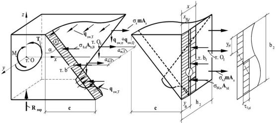
forced concrete structure under the combined action of a bending moment, torque and shear force (case 2) is shown in Fig. 2.
Fig. 2. Design diagram of the resistance of a reinforced concrete structure under the combined action of bending moment, torque and shear force (case 2):
 is a compressed zone of the spatial section;
  is a compressed zone of the section I–I
In order to construct the design equations, two blocks are separated from the reinforced concrete element using the section method (Fig. 2). The first block is separated by the crosssection I–I pas-sing at the end of the spatial crack. This block is in equilibrium under the action of external forces applied to the block from the support side and internal forces arising at the site of the section.
Based on the equilibrium equation of the moments of internal and external forces in this section I-I relative to the point passing through the point of application of the resultant forces in the stretched reinforcement (∑MO,I = 0), we get:
σb,I Ab[h0 − ϕ y,2 (xb, x) x]− M − Rsupam,S = 0 , |
(14) |
where am,S is a horizontal distance from the support in the direction of the y-axis to the center of gravity of the working longitudinal reinforcement in the section I-I (pointО1 ). In this case, it should be emphasized that the moment created by Rsup am,S will be torsional relative to the x axis and relative to point O1 ; the moment M will be bending with respect to the y-axis and with
respect to the pointO ; the moment created byσ |
A h −ϕ |
y,2 |
(x , x) x will be bending about |
|
1 |
b,I b 0 |
b |
|
|
the z-axis and about the pointO1 . Here ϕ y,2 (xb , x)is a static-geometric parameter that considers
the location of the center of gravity of the compressed zone of concrete in section I-I (in section хb, the diagram of compressive stresses is rectangular, in section х-хb triangular); Rsup is a support
13

Russian Journal of Building Construction and Architecture
reaction in the first block (Fig. 2), (for the second group of limiting states this parameter is known). The unknown σb,I is given by this equation.
Based on the equilibrium equation of the projections of all forces acting in section I – I on the x axis, the height of the compressed concrete zone x in this section is found. The equation takes the following form:
|
|
|
|
σ b ϕпр(σ i ,εi ) ϕα (c) ϕ y,2 (xb, x) b x −σ s,1mAs,1 = 0 , |
(15) |
||
where |
ϕпр |
( |
,ε і |
) is a parameter that considers the projection of the σ |
– ε |
diagram on the di- |
|
|
σ і |
і |
і |
|
|
||
rection perpendicular to the plane k (Fig. 2); ϕα is a parameter that considers the projection of stress components in the k plane onto the I-I plane, perpendicular to the longitudinal axis of the reinforced concrete element; ϕy,2 (xb, x)is a parameter equal to the parameter up to a nu-
merical ϕ y (xb, x).
Based on the equilibrium equation of the moments of internal and external forces acting in section I-I relative to the axis perpendicular to this section and passing through the point of application of the resultant forces in the compressed zone (Tb,I = 0), we get:
2 0.5τ |
T |
b |
|
2 |
b |
x − T = 0 . |
(16) |
|
2 |
|
3 |
2 |
|
|
Using this equation, the unknown T (for the first group of limit states) is identified and if T is specified through the ratio Rsup:T and when considering the second group of limit states, this
equation is used to determineτ T . |
|
This equation is the same as equation (16). The condition (17) is checked: |
|
τT ≤τT , pl . |
(17) |
If the condition (17) is not met, τT is assumed to be equal to τT,pl and the transformed equation (16) is used to identify the parameter ypl (see equation (18) and Fig. 2):
2 [τ T,pl ypl (b / 2 − 0.5ypl )+ 0.5τT , pl (b / 2 − ypl )2 / 3(b / 2 − ypl )] x − T = 0 . (18) It should be noted that for scheme II, the τT diagram is commonly close to rectangular.
Based on the hypothesis of proportionality of longitudinal deformations (the equation is similar to (19), we find σ s,I :
σ s,I |
= |
σ b Es (λ ) |
|
h0 |
− x |
. + σ |
0 . |
(19) |
|
Eb |
(λ ) |
|
x |
||||||
|
|
|
|
|
|
|
|||
14

Issue № 3 (47), 2020 |
ISSN 2542-0526 |
The condition (20) must be checked. If the condition (20) is not met, σs,I is assumed to be
equal to Rs. |
|
σs,I ≤ Rs . |
(20) |
While considering the second block, in the same way as in the first scheme, equilibrium equations are drawn up. The sum of the moments with respect to the z axis relative to the point of application of the resultant forces in the compressed zone is equal to zero (∑Mb = 0, block II):
σ smAs (h0 − 0.5xb ) − M − Rsup am,b = 0 . |
(21) |
The equation (21) is used to identify the unknown σs. Using the equation of equilibrium of the moments of internal and external forces in the spatial section with respect to the z-axis relative to the point ОК of application of the resultant forces (section k, Fig. 2) in compressed concrete (∑MО,К =0), the stresses in compressed concrete of the section k σb are calculated:
σ b Ab (h0 − 0.5xb ) − M − Rsup am,S = 0 . |
(22) |
Using the equation of the sum of the projections of all forces acting in the spatial section on the x axis, the unknown xb (∑X=0, block II).
σ |
ϕ |
пр |
(σ |
,ε |
) ϕ |
α |
(c) x |
b |
|
c2 + b2 − σ |
mA |
− 2q |
2 sw |
(h |
− x |
)2 + c2 |
= 0 . (23) |
b |
|
i |
i |
|
|
|
|
s s |
|
0 |
b |
|
|
The sum of the moments of internal and external forces in the vertical transverse plane relative to the x-axis passing through the point of application of the resultant forces in the compressed zone is equal to zero (∑Tb = 0, block II):
(q |
sw,σ |
+ q |
sw,Q |
) c2 + b2 (h − 0,5 x |
) − 2q |
sw,T |
(h − x |
)2 + c2 |
− 2τ |
T |
ω x |
b |
− T = 0. (24) |
||
|
|
0 |
b |
|
0 |
b |
|
|
|
|
|||||
The equation (24) is used to identify the unknown qsw,T .
The sum of the projections of all forces acting in the spatial section on the z axis is zero (∑Z = 0, block II):
(qsw,σ + qsw,Q )  c2 + b2 + σ b ϕпр (σ i ,ε i ) ϕα1 (c) xb
  c2 + b2 −τ T xb (
 c2 + b2 ) = 0 . (25) The equation (25) is used to identify the unknown qsw,Q.
The unknown qsw,σ is found using the following considerations. This linear force arises on the la-teral face from the action of Т+Rsup eQ as well as the linear force qsw,Т arising on the upper and lower edges, thus its difference from the latter will consist in taking into account the ratio b2 : h2 and the characteristics of the reinforcement used. Then
qsw,σ |
= |
h |
Rsw,σ |
Asw,σ |
=nT. |
(26) |
||
|
|
2 |
|
|
|
|||
q |
|
R |
|
A |
||||
sw,Q |
|
b |
sw,T |
|
|
|||
|
|
2 |
|
sw,T |
|
|
||
15

Russian Journal of Building Construction and Architecture
Hence
qsw,σ = qsw,T nT . |
(27) |
The “dowel forces” in the longitudinal Qs and transverse reinforcement qsw,2 are determined from a special model of the “dowel effect” considered in [11]. Thus, the considered method for calculating the resistance of reinforced concrete structures under the combined action of a bending moment, torque and shear force for the second stage of the stress-strain state (case 2) can be used when spatial cracks of the first type appear on the side face of the structure.
3. Calculation of the distance between spatial cracks and the width of their opening in reinforced concrete structures in torsion with bending (case 1).
While calculating the resistance of reinforced concrete structures to the action of transverse forces, bending and torque moments, it becomes necessary to assess the complex stress-strain state, which is even more complicated in the presence of spatial cracks.
Following the formation of cracks, the continuity of concrete is violated and the application of the formulas of the mechanics of a solid deformed body is no longer legitimate. Nevertheless, in order to determine the actual stress-strain of reinforced concrete structures, it becomes necessary to consider the complete picture of cracking during loading. In this case, it is important not only to have different levels of cracking of spatial cracks, but also to have their complete picture.
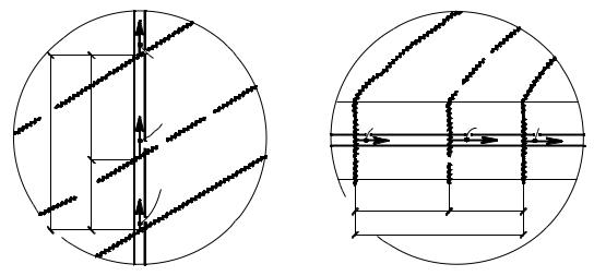
Fig. 3. Calculation scheme for determining the distance between cracks of the first type (case 1):
a is a scheme of efforts and the choice of a coordinate system for the formation of the first spatial crack
16
Issue № 3 (47), 2020 |
ISSN 2542-0526 |
First of all, it is essential to apply the entire fan of spatial cracks of all types. After identifying a dangerous spatial crack according to the criterion of formation or the largest width of their opening, it is necessary to apply the whole picture of spatial cracks.
At the same time, as the practice of calculations and design of reinforced concrete structures has shown, the distance between spatial cracks of the first type for the first level of cracking lcrc,1 located along the transverse or longitudinal reinforcement, can be determined from the following relationship (Fig. 3, Fig. 4).
|
|
а) |
|
|
σsw,crc,up |
crc,1 |
crc2,up |
σsw |
|
||
l |
|
|
l |
|
|
|
crc2,d |
σsw,crc,d |
|
|
|
|
l |
|
b)
σs,crc,lef |
σs |
σs,crc,rig |
lcrc2,lef |
l crc2,rig |
|
lcrc,1 |
Fig. 4. Location of the adjacent crack of the next level between two cracks of the previous level:
a is along the axis of the transverse reinforcement; b is along the axis of the longitudinal reinforcement
|
a |
= |
|
σ S,I |
. |
|
(28) |
|
|
a-lcrc,1 |
σ S ,crc |
|
|||||
|
|
|
|
|||||
Hence |
|
|
|
|
|
|
||
lcrc,1 = |
a (σ S,I − σ S ,crc ) |
. |
(29) |
|||||
|
||||||||
|
|
|
|
|
σ S,I |
|
|
|
In order identify the distance between spatial cracks of the second level of their formation, the ratio between the stresses in the reinforcement in section I – I and in the section with a dangerous spatial crack is used, which is given by the criterion of the maximum width of their opening:
|
a |
= |
|
σ S,I |
. |
|
(30) |
|
|
a-lcrc,2 |
σ S ,С |
|
|||||
|
|
|
|
|||||
Hence |
|
|
|
|
|
|
||
lcrc ,2 = |
a (σ S,I − σ S ,С ) |
. |
(31) |
|||||
|
||||||||
|
|
|
|
|
σ S,I |
|
|
|
17

Russian Journal of Building Construction and Architecture
In this case, the emergence of a new level of cracking corresponds to the level of load where the following inequality is observed:
lcrc,i ≤ η lcrc,i-1 , |
(32) |
where η along the transverse reinforcement from a dangerous inclined crack is given by the following ratios (Fig. 4, b):
σ Sw,crc,d |
|
= |
lcrc,2,up |
=ηw ; |
(33) |
σ Sw,crc,up |
|
|
|||
|
|
lcrc,2,d |
|
||
lcrc,2,up |
+ lcrc,2,d = lcrc,1 . |
(34) |
|||
While moving to the right along the longitudinal reinforcement, the following ratios are obtained (Fig. 4, b):
|
σS,crc,rig |
|
= |
lcrc,2,lef |
= η , |
(35) |
|
|
σ |
|
|
|
|||
|
S,crc,lef |
|
|
l |
|
||
|
|
|
|
crc,2,rig |
|
||
|
lcrc,2,lef |
+ lcrc,2,rig = lcrc,1 . |
(36) |
||||
While moving to the left of a dangerous spatial crack, the functional lcrc and |
l* are compared |
||||||
(see Fig. 4) and, if necessary, similar ratios are used: We do not move beyond the section where
:
lcrc,lef ,* |
= |
|
σ S, С |
=η* , |
(37) |
lcrc,rig ,* |
|
||||
|
σ s,сrc |
|
|||
lcrc,lef ,* + lcrc,rig,* = l* . |
(38) |
||||
We do not move beyond the section restrained by lcrc ,1 (Fig. 4), either.
In the case of breaks of longitudinal reinforcement in the section of spatial inclined cracks, relations (35) and (37) are somewhat modified, i.e., in addition to the ratio of stresses in the reinforcement, the ratios of the areas of longitudinal reinforcement (prior and following the break) are also consi-dered. As a result, while moving to the right, these formulas will take the following form:
l |
crc,lef |
= |
|
σ |
S,I |
|
AS, |
rig |
=η ; |
(39) |
|
lcrc,rig |
σ S,С |
AS, lef |
|||||||||
|
|
|
|
||||||||
while moving to the left:
18
Issue № 3 (47), 2020 |
ISSN 2542-0526 |
l |
crc,lef ,* |
= |
|
σ |
S,C |
|
AS, |
rig ,* |
= η* . |
(40) |
lcrc,rig,* |
σ S,сrc |
|
|
|||||||
|
|
AS,lef ,* |
|
|||||||
Hence cracking continues until the moment of destruction. At the same time, not one stands out (as is common in a number of known techniques), but several levels of cracking:
|
|
lcrc |
> lcrc ,1 − Nтoрещинcracks; |
нет ; |
|||
lcrc ,1 |
≥ lcrc |
> lcrc ,2 − Firstпервыйlevel; |
уровень |
||||
l |
crc , 2 |
≥ l |
crc |
> l |
crc ,3 |
− второй |
уровень |
|
|
|
Second level; |
||||
. . . . . . . . . . . . . . . . . . . . . . . . . . . |
|
||||||
lcrc ≥ 6t* |
|
− последнийLast level. |
уровень |
||||
;
; . (41)
.
While comparing the functional and level values lcrc , possible implementation of the emergence of subsequent levels of fracturing is analyzed.
Having the levels of cracking along the longitudinal and transverse reinforcement of the reinforced concrete structure, it is possible to obtain a complete picture of various cracks adjacent to the concentrated force and to the support (Fig. 3) and identify the width of their opening. In this case, crack opening is defined as the accumulation of relative conditional concentrated mutual displacements of reinforcement and concrete in areas located on both sides of the crack:
t |
0.5lcrc −t |
|
|
acrc = 2 ε g (x1 )dx1 + 2 |
|
ε g (x)dx , |
(42) |
0 |
0 |
|
|
4. Calculation of the distance between spatial cracks and the width of their opening in reinforced concrete structures in torsion with bending (case 2). For case 2, as in case 1, the distance between spatial cracks of the first type can be given by the ratio (28) (Fig. 5, Fig. 6).
Hence
lcrc,1 |
= |
a (σ S,I − σ S ,crc ) |
. |
(43) |
|
||||
|
|
σ S,I |
|
|
In order to identify the distance between spatial cracks of the second level for case 2 as well as for case 1, relation (30) is used hence
lcrc,2 |
= |
a (σ S,I − σ S ,С ) |
. |
(44) |
|
||||
|
|
σ S,I |
|
|
19