

Licensed for single user. © 2017 ASHRAE, Inc.
This file is licensed to John Murray (John9@gmail.com). Publication Date: 6/1/2017
Related Commercial Resources
CHAPTER 16
VENTILATION AND INFILTRATION
Basic Concepts and Terminology ............................................ |
16.1 |
Residential Ventilation ........................................................... |
16.18 |
Tracer Gas Measurements....................................................... |
16.5 |
Residential IAQ Control......................................................... |
16.20 |
Driving Mechanisms for Ventilation and |
|
Simplified Models of Residential Ventilation and |
|
Infiltration ............................................................................ |
16.7 |
Infiltration .......................................................................... |
16.23 |
Indoor Air Quality ................................................................. |
16.11 |
Commercial and Institutional Air Leakage............................ |
16.26 |
Thermal Loads ....................................................................... |
16.11 |
Commercial and Institutional Ventilation.............................. |
16.29 |
Natural Ventilation ................................................................ |
16.13 |
Office Building Example ........................................................ |
16.30 |
Residential Air Leakage......................................................... |
16.15 |
Symbols .................................................................................. |
16.33 |
PROVIDING a comfortable and healthy indoor environment for building occupants is the primary concern of HVAC engineers.
Comfort and indoor air quality (IAQ) depend on many factors, including thermal regulation; control of internal and external sources of pollutants; supply of acceptable air; removal of unacceptable air; occupants’ activities and preferences; and proper construction, operation, and maintenance of building systems. Proper ventilation and infiltration are only part of achieving acceptable indoor air quality and thermal comfort. HVAC designers, occupants, and building owners must be aware of and address other factors as well. Further information on indoor environmental health may be found in Chapter 10. Changing ventilation and infiltration rates to solve thermal comfort problems and reduce energy consumption can affect indoor air quality and may be against building code or other regulations, so any changes should be approached with care and be under the direction of a registered professional engineer with expertise in HVAC analysis and design.
HVAC design engineers and others concerned with building ventilation and indoor air quality should obtain a copy of ASHRAE Standard 62.1 or 62.2, or those for specific applications (e.g., Standard 170 for health care), whichever is most relevant to the project. These standards are reviewed regularly and contain ventilation design and evaluation requirements for commercial and institutional (Standard 62.1) and residential (Standard 62.2) buildings, respectively. When designing a new building or analyzing an existing building, check which version of Standard 62 has been adopted by the local code authority. An existing building may be required to meet the current version of the standard, or allowed to comply with an older version. The last chapter of each year’s ASHRAE Handbook (Chapter 39 of this volume) has a list of current standards.
This chapter addresses commercial and institutional buildings, where ventilation concerns usually dominate (though infiltration should not be ignored), and singleand multifamily residences, where infiltration has traditionally been considered most important but ventilation issues have received increased attention in recent years. Basic concepts and terminology for both are presented before more advanced analytical and design techniques are given. Ventilation of industrial buildings is covered in Chapter 31 of the 2015
ASHRAE Handbook—HVAC Applications. However, many of the fundamental ideas and terminology presented in this chapter can also be applied to industrial buildings.
Sustainable Building Standards and Rating Systems
Good indoor air quality is necessary for maintaining health and high productivity. Consequently, sustainable building standards such as ASHRAE Standard 189.1 and building rating systems, such
The preparation of this chapter is assigned to TC 4.3, Ventilation Requirements and Infiltration.
as U.S. Green Building Council’s (USGBC) Leadership in Energy and Environmental Design™ (LEED®) program, place great importance on creating and maintaining acceptable IAQ. In fact, the LEED rating system was first developed to address IAQ concerns, and roughly one-quarter of the available credit points for new commercial buildings are still IAQ related. Preparers of such rating systems, like others, have struggled with how to characterize complex ventilation and infiltration issues. These issues are addressed in detail by many portions of this chapter; separate ASHRAE design guides, manuals, books, and standards; and the references cited; these sources also provide methods to demonstrate the effectiveness of various HVAC systems and techniques in providing good IAQ in residential, commercial, and other buildings. In all designs, care is needed to eliminate excessive ventilation (e.g., beyond that needed for IAQ or by an air-side economizer) to avoid inappropriately increasing energy use. Increasing the ventilation rate above that required by Standard 62.1, for example, does not necessarily increase the acceptability of the indoor air quality.
1.BASIC CONCEPTS AND TERMINOLOGY
Outdoor air that flows through a building is often used to dilute and remove indoor air contaminants. However, the energy required to condition this outdoor air can be a significant portion of the total space-conditioning load. The magnitude of outdoor airflow into the building must be determined to size the HVAC equipment properly, and to evaluate energy consumption (if required). For buildings without mechanical cooling and dehumidification, proper ventilation and infiltration airflows are important for providing acceptable IAQ and better thermal comfort for occupants. ASHRAE Standard 55 specifies conditions under which 80% or more of the occupants in a space will find it thermally acceptable. Chapter 9 of this volume also addresses thermal comfort.
Airflow into buildings and between zones also affects fires, smoke movement, and safe occupant egress. Smoke management is addressed in Chapter 53 of the 2015 ASHRAE Handbook—HVAC
Applications.
Ventilation and Infiltration
Air exchange of outdoor air with air already in a building can be divided into two broad classifications: ventilation and infiltration.
Ventilation is intentional introduction of air from the outdoors into a building; it is further subdivided into natural and mechanical ventilation. Natural ventilation is the flow of air through open windows, doors, grilles, and other planned building envelope penetrations. Mechanical (or forced) ventilation, shown in Figure 1, is the intentional movement of air into and out of a building using fans, ductwork, intake louvers, and exhaust grilles, for example.
Infiltration is the flow of outdoor air into a building through cracks and other unintentional openings and through the normal use
16.1
Copyright © 2017, ASHRAE

This file is licensed to John Murray (John9@gmail.com). Publication Date: 6/1/2017
16.2 |
2017 ASHRAE Handbook—Fundamentals (SI) |
Licensed for single user. © 2017 ASHRAE, Inc.
Fig. 1 Two-Space Building with Mechanical Ventilation, Infiltration, and Exfiltration
of exterior doors for entrance and egress. Infiltration is also known as air leakage into a building. Exfiltration, depicted in Figure 1, is leakage of indoor air out of a building through similar types of openings. Like natural ventilation, infiltration and exfiltration are driven by natural and/or artificial pressure differences. These forces are discussed in detail in the section on Driving Mechanisms for Ventilation and Infiltration. Transfer air is air that moves from one interior space to another, either intentionally or not.
Ventilation and infiltration differ significantly in how they affect energy consumption, air quality, and thermal comfort, and can each vary with weather conditions, HVAC system operation, and building use. Although one mode may be expected to dominate in a particular building, both must be considered in the proper design and operation of an HVAC system. Seasonal weather and other transient factors must be considered, as well.
Ventilation Air
Ventilation air is air used to provide acceptable indoor air quality. It may be composed of mechanical or natural ventilation, infiltration, suitably treated recirculated air, transfer air, or an appropriate combination, although the allowable means of providing ventilation air varies in standards and guidelines.
Modern commercial and institutional buildings normally have mechanical ventilation and are usually intended to be pressurized somewhat to reduce or eliminate infiltration. Mechanical ventilation has the greatest potential for control of air exchange when the system is properly designed, installed, and operated; it should provide acceptable indoor air quality and thermal comfort when ASHRAE Standards 55 and 62.1’s requirements are followed, although issues (e.g., unusually strong pollutant sources) can still result in unacceptable indoor environment conditions. Mechanical ventilation equipment and systems are described in Chapters 1, 4, and 10 of the 2016
ASHRAE Handbook—HVAC Systems and Equipment.
In commercial and institutional buildings, natural ventilation (e.g., through uncontrolled use of manually operated windows) may not be desirable from the points of view of energy conservation, comfort, security, or control of airborne pollen or other pollutants in some climates and locations. In commercial and institutional buildings with mechanical cooling and ventilation, an automatically controlled airor water-side economizer may be preferable to operable windows for taking advantage of cool outdoor conditions when interior cooling is required. When moderate outdoor temperatures occur, an air-side economizer control scheme may not only increase the rate of ventilation but also operate the cooling equipment to optimize energy use (hybrid or mixed mode).
Infiltration may be significant in commercial and institutional buildings too, especially in tall, leaky, or partially pressurized buildings and in lobby and loading dock areas. The joint between roof decking and outer walls is often particularly leaky in commercial and other large buildings, and should be properly detailed, constructed, and inspected.
Fig. 2 Simple All-Air Air-Handling Unit with
Associated Airflows
In most of the United States, residential buildings have historically relied on infiltration and natural ventilation to meet their ventilation air needs. Neither is reliable for ventilation air purposes because they depend on weather conditions, building construction, occupants, and maintenance. Natural ventilation, usually through operable windows and screened doors, is more likely to allow occupants to control indoor airborne contaminants and interior air temperature, but it can have a substantial energy cost if used while the residence’s heating or cooling equipment is operating. Opened windows and doors also may lead to security, noise, or other concerns.
In place of or in addition to operable windows, small exhaust fans should be provided for localized venting of residential spaces with high pollutant levels or moisture (e.g., kitchens, bathrooms). Not all local building codes require that such exhaust be vented to the outdoors, but it is required by ASHRAE Standard 62.2. Instead, a local code may allow the air to be treated and returned to the space or to be discharged to an attic space. Poor maintenance of these recirculating treatment devices can make nonducted vents ineffective for ventilation purposes. Warm exhaust air can hold much moisture, so condensation in attics should be avoided. If not already required by code, consider venting attached garages and other storage spaces to the outdoors, as well.
Increasingly, building codes require general mechanical ventilation in residences. Heat recovery heat exchangers are popular for reducing energy consumption, especially in cold climates. Residential buildings with low rates of infiltration and natural ventilation, including most new buildings, require mechanical ventilation at rates given in ASHRAE Standard 62.2.
Forced-Air Distribution Systems
Figure 2 shows a simple air-handling unit (AHU) or air handler that conditions air for a building. Air brought back to the air handler from the conditioned space is return air (RA). The return air either is discharged to the environment [exhaust air (EA)] or is reused [recirculated air (CA)]. Air brought in intentionally from the environment is outdoor air (OA). Because outdoor air may need treatment to be acceptable for use in a building, it should not be called “fresh air.” Outdoor and recirculated air are combined to form mixed air (MA), which is then conditioned and delivered to the spaces served as supply air (SA). Any portion of the mixed air that intentionally or unintentionally circumvents conditioning is bypass air (BA). Because of the wide variety of air-handling systems, the airflows shown in Figure 2 may not all be present in a particular system as defined here. Also, more complex systems may have additional airflows.
Licensed for single user. © 2017 ASHRAE, Inc.
This file is licensed to John Murray (John9@gmail.com). Publication Date: 6/1/2017
Ventilation and Infiltration |
16.3 |
In HVAC design, volumetric airflow rates Q are normally reported in litres per second (L/s) or cubic metres per second (m3/s). The incorrect term “volume” should not be used to describe airflow rates.
Outdoor Air Fraction
The outdoor airflow introduced to a building or zone by an airhandling unit can also be described by the outdoor air fraction Xoa, which is the ratio of the volumetric flow rate Q of outdoor air brought in by the air handler to the total supply airflow rate:
X |
= |
Qoa |
= |
Qoa |
= |
Qoa |
(1) |
--------- |
---------- |
------------------------ |
|||||
oa |
|
Qsa |
|
Qma |
|
Qoa + Qca |
|
|
|
|
|
|
When expressed as a percentage, the outdoor air fraction is called the percent outdoor air. The design outdoor airflow rate Qoa for a building’s or zone’s ventilation system is found by applying the requirements of ASHRAE Standard 62.1 or 62.2 to that specific building, occupancy, and HVAC system. The supply airflow rate Qsa is that required to meet the thermal load. The outdoor air fraction and percent outdoor air then describe the degree of recirculation, where a low value indicates a high rate of recirculation, and a high value shows little recirculation. Conventional all-air air-handling systems for commercial and institutional buildings often have approximately 10 to 40% outdoor air.
100% outdoor air means no recirculation of return air through the air-handling system. Instead, all the supply air is treated outdoor air, also known as makeup air (KA), and all return air is discharged directly to the outdoors as relief air (LA), via separate or centralized exhaust fans or relief dampers and grilles. An air-handling unit that provides exclusively 100% outdoor air to offset air that is exhausted is typically called a makeup air unit (MAU).
When outdoor air via mechanical ventilation is used to provide ventilation air, as is common in commercial and institutional buildings and increasingly in residences, this outdoor air is usually delivered to spaces as all or part of the supply air. With a variable- air-volume (VAV) system, the outdoor air fraction of the supply air may need to be increased when supply airflow is reduced to meet a particular thermal load. In some HVAC systems, such as a dedicated outdoor air system (DOAS), conditioned outdoor air may be delivered separately from the way the spaces’ loads are handled (Mumma and Shank 2001).
Room Air Movement
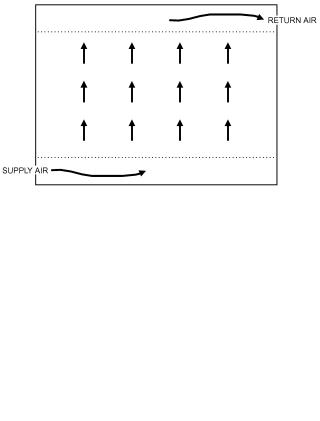
Air movement within spaces affects the diffusion of ventilation air and, therefore, indoor air quality and comfort. Two distinct flow patterns are commonly used to characterize air movement in rooms: displacement flow and entrainment flow. Displacement flow, shown in Figure 3, is the movement of air within a space in a pistonor plug-type motion. Ideally, no mixing of the room air occurs, which is desirable for removing pollutants generated within a space. Air mixing does occur, however, to various degrees. A laminarflow air distribution system that is intended to sweep air across a space with reduced turbulence and mixing may produce a high degree of displacement flow and thus more effective pollutant removal. The pollutants’ buoyancy and occupants’ thermal comfort are concerns when deciding on the intended direction of airflow.
Entrainment flow, shown in Figure 4, is also known as conventional mixing. Systems with ceiling-based supply air diffusers and return air grilles are common examples of air distribution systems that produce entrainment flow. Airborne pollutants are removed by dilution by the ventilation air that is delivered as all or part of the supply air. Entrainment flow with very poor mixing in the room has been called short-circuiting flow because much of the supply air leaves the room without mixing with room air. There is little evidence that properly designed, installed, and operated air distribution
Fig. 3 Displacement Flow Within a Space
Fig. 4 Entrainment Flow Within a Space
systems exhibit substantial short circuiting, although poorly designed, installed, or operated systems may short circuit (especially ceiling-based systems in heating mode) to a higher degree (Offermann and Int-Hout 1989).
Theoretical perfect mixing occurs when supply air is instantly and evenly distributed throughout a space. Perfect mixing is also known as complete or uniform mixing; the air may be called well stirred or well mixed. This theoretical performance is approached by entrainment flow systems that have good mixing and by displacement flow systems that allow too much mixing (Rock et al. 1995). The outdoor air requirements given in the minimum ventilation rate in breathing zone table of ASHRAE Standard 62.1 assume delivery of ventilation air with perfect mixing within spaces. For more detailed information on space air diffusion, see Chapter 20.
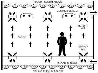
Underfloor air distribution (UFAD or UAD), as shown in Figure 5, is a hybrid method of conditioning and ventilating spaces (Bauman and Daly 2003). Air is introduced through a floor plenum, with or without branch ductwork or terminal units, and delivered to a space by floor-mounted diffusers. These diffusers encourage air mixing near the floor to temper the supply air for thermal comfort. The combined air then moves vertically through the space, with reduced mixing, toward returns or exhausts placed in or near the ceiling. This vertical upward movement of the air is in the same direction as the thermal and contaminant plumes created by occupants and common equipment. The ventilating performance of UFAD systems is thus often between floor-to-ceiling displacement flow and uniform mixing.
Supply air that enters a space through a diffuser, grille, or nozzle is also known as primary air. An air jet is formed as this primary air leaves the supply air outlet. Secondary air is the room air entrained into the jet. Total air is the combination of primary and
Licensed for single user. © 2017 ASHRAE, Inc.
This file is licensed to John Murray (John9@gmail.com). Publication Date: 6/1/2017
16.4 |
2017 ASHRAE Handbook—Fundamentals (SI) |
Fig. 5 Underfloor Air Distribution to Occupied Space Above
(Rock and Zhu 2002)
secondary air at a specific point in a jet and increases with distance from the outlet as is described further in Chapter 20. The term primary air is also used to describe supply air provided to fan-powered mixing boxes by a central air-handling unit.
For evaluation of indoor air quality and thermal comfort, rooms are often divided into two portions: the occupied zone and the remaining volume of the space. Often, this remaining volume is solely the space above the occupants and is referred to as the ceiling zone. The occupied zone is usually defined as the lowest 1.8 m of a room, although layers near the floor and walls are sometimes deducted from it; when these deductions are made, the occupied zone is sometimes renamed the breathing zone. Ceiling and floor plenums are not normally included in the occupied or ceiling zones. Thermal zones are different from these room air zones, and are defined for HVAC subsystems and their controls.
Air Change Rate
The air change (or exchange) rate I compares airflow to the space’s volume and is
I = Q/V |
(2) |
where
Q = volumetric flow rate of air into space, m3/s V = interior volume of space, m3
The air change rate has units of 1/time, usually h–1. When the time unit is hours, the air change rate is also called air changes per hour (ACH), with units of h–1. The air change rate may be defined for several different situations. For example, the air change rate for an entire building or thermal zone served by an air-handling unit compares the amount of outdoor air brought into the building or zone to the total interior volume. This nominal air change rate IN is
IN = Qoa /V |
(3) |
where Qoa is the outdoor airflow rate including ventilation and infiltration. IN describes the outdoor air ventilation rate entering a building or zone. It does not describe recirculation or the distribution of ventilation air to each space in a building or zone.
For a particular space, the space air exchange rate IS compares the supply airflow rate Qsa to the volume of that space:
IS = Qsa /V |
(4) |
For a particular space or zone, IS includes recirculated as well as any outdoor air in the supply air, and is used frequently in evaluating supply air outlet performance and space air mixing.
Time Constants
Time constants , which have units of time (usually in hours or seconds), are also used to describe ventilation and infiltration. One time constant is the time required for one air change in a building, zone, or space if ideal displacement flow existed. It is the inverse of the air change rate:
= 1/I = V/Q |
(5) |
The nominal time constant compares the interior volume of a building or zone to the volumetric outdoor airflow rate:
N = V/Qoa |
(6) |
Like the nominal air change rate, N does not describe recirculation of air in a building or zone, or characterize the distribution of the outdoor air to individual spaces in a building or zone.
The space time constant compares the interior volume of a particular space to the total supply airflow rate to that space. The space time constant is the inverse of the space air change rate:
S = V/Qsa |
(7) |
The space time constant includes the effect of recirculated air that is part of the supply air as well as that of outdoor air introduced to the space through the supply air. If infiltration is significant in a space, then the infiltration flow rate should be included when determining both the space air change rate and the space time constant.
Averaging Time-Varying Ventilation Rates
When assessing time-varying ventilation in terms of controlling indoor air quality, the quantity of interest is often the temporal average rather than the peak. The concept of effective ventilation (Sherman and Wilson 1986; Yuill 1986, 1991) describes the proper ventilation rate averaging process. In this concept, the average (effective) rate is the steady-state rate that yields the same average contaminant concentration over the period of interest in the occupied space as does the actual sequence of time-varying discrete ventilation rates over the same period and in the same space. This effective rate is only equal to the simple arithmetic average rate when the discrete ventilation rates are constant over the period of interest and the contaminant concentration has reached its steadystate value. Simple arithmetic averaging of instantaneous ventilation rates or concentrations cannot generally be used to determine these averages because of the nonlinear response of indoor concentrations to ventilation rate variations.
An important constraint in the effective ventilation concept is that the contaminant source strength F must be constant over the period of interest or must be uncorrelated with the ventilation rate. These conditions are satisfied in many residential and commercial buildings because the emission rates of many contaminants that are controlled by whole-building ventilation systems vary slowly. Sherman and Wilson (1986) describe how to deal with pollutants that have stepped but otherwise constant emission rates. Pollutants such as carbon monoxide, radon, and formaldehyde, whose emission rates can be affected by ventilation, cannot be properly characterized with this concept and require more complex analyses. For constant-source-strength pollutants, the relationship between effective air change rate, effective ventilation rate, volumetric flow, source strength, average concentration, and time-averaged effective turnover time is given by
|
|
|
|
|
|
|
|
1 |
|
|
Q |
|
F |
(8) |
|||||
Im = |
---- |
= |
------- |
|
= ---- |
||||
|
V |
|
|
|
|
e |
|
||
|
|
VC |
|
||||||
Licensed for single user. © 2017 ASHRAE, Inc.
This file is licensed to John Murray (John9@gmail.com). Publication Date: 6/1/2017
Ventilation and Infiltration |
|
|
|
|
|
16.5 |
|
The time-averaged effective turnover time |
|
e in Equation (8) |
proposed. The specific measure that meets local code requirements |
||||
|
|||||||
represents the characteristic time for the concentration in the occu- |
must be determined, if any is needed at all. |
|
|||||
pied space to approach steady state over the period of interest. It can |
Air change effectiveness measures I are nondimensional gages |
||||||
be determined from a sequence of discrete, instantaneous ventila- |
of ventilation air delivery. One common definition of air change |
||||||
tion air change rates Ii using the following (Sherman and Wilson |
effectiveness is the ratio of a time constant to an age of air: |
|
|||||
1986): |
|
|
|
|
|
I = / age |
(13) |
|
|
|
|
|
|
||
1 |
N |
e, i |
(9) |
The nominal air change effectiveness I,N shows the effective- |
|||
e = --- |
|
||||||
N |
|
|
|
|
ness of outdoor air delivery to the entire building, zone, or space: |
||
|
i=1 |
|
|
|
|
|
|
1 – exp –Ii |
t |
(10) |
I, N = N / age, N |
(14) |
|||
for Ii > 0, e, i = ------------------------------------ + e, i – 1 exp(–Ii t) |
where the nominal time constant N is usually calculated from mea- |
||||||
Ii |
|
|
|
|
|
||
for Ii = 0, e, i = t + te, i – 1 |
(11) |
sured airflow rates. |
|
||||
The local air change effectiveness I,L shows the effectiveness |
|||||||
where |
|
|
|
|
|
of outdoor air delivery to one specific point in a space: |
|
|
|
|
|
|
|
|
|
t |
= length of each discrete time period |
e |
= time-averaged effective turnover time |
e, i |
= instantaneous turnover time in period i |
e, i–1 |
= instantaneous turnover time in previous period |
ASHRAE Standard 62.2 provides a set of factors to help calculate the annual effective air exchange rate.
Age of Air
The age of air age (Sandberg 1981) is the length of time t that some quantity of outdoor air has been in a building, zone, or space.
The “youngest” air is at the point where outdoor air enters the building by mechanical or natural ventilation, or through infiltration (Grieve 1989). The “oldest” air may be at some location in the building or in the exhaust air. When the characteristics of the air distribution system are varied, age of air is inversely correlated with quality of outdoor air delivery. Units are of time, usually in seconds or minutes, so it is not a true efficiency or effectiveness measure. The age of air concept, however, has gained wide acceptance in Europe.
The age of air can be evaluated for existing buildings using tracer gas methods. Using either the decay (step-down) or growth (stepup) tracer gas method and assuming perfect mixing, the zone aver-
age or nominal age of air age,N can be determined by taking concentration measurements in the exhaust air. The local age of air
age,L is evaluated through tracer gas measurements at any desired point in a space, such as at a worker’s desk. When time-dependent data of tracer gas concentration are available, the age of air can be calculated from
|
|
= |
|
Cin |
– C |
(12) |
|
|
-------------------- dt |
||||
|
age |
|
t=0 Cin |
– Co |
|
|
where Cin is the concentration of tracer gas being injected. Because evaluation of the age of air requires integration to in-
finite time, an exponential tail is usually added to the known concentration data (Farrington et al. 1990).
Air Change Effectiveness
Ventilation effectiveness is a description of an air distribution system’s ability to remove internally generated pollutants from a building, zone, or space. Air change effectiveness is a description of an air distribution system’s ability to deliver ventilation air to a building, zone, or space. The HVAC design engineer usually does not have knowledge or control of actual pollutant sources within buildings, so the minimum prescribed ventilation rates of ASHRAE Standard 62.1 define outdoor air requirements for typical, expected building uses. For most projects, therefore, air change effectiveness is of more relevance to HVAC system design than ventilation effectiveness. Various definitions for air change effectiveness have been
I, L = N / age, L |
(15) |
where N is found either through airflow measurements or from tracer gas concentration data. An I,L value of 1.0 indicates that the air distribution system delivers air equivalent to that of a system with perfectly mixed air in the spaces. A value less than 1.0 shows less than perfect mixing with some degree of stagnation. A value ofI,L greater than 1.0 suggests that a degree of plug or displacement flow is present at that point (Rock 1992).
An HVAC design engineer often assumes that a properly designed, installed, operated, and maintained air distribution system provides an air change effectiveness of about 1. However, the zone air distribution table of ASHRAE Standard 62.1 provides some estimates of effectiveness for operating in heating or cooling mode, and with various air distribution techniques. These values are then adjusted for commercial and institutional building design when the ventilation rate procedure (VRP) is used. If the IAQ procedure of Standard 62.1 is used, then actual pollutant sources and the air change effectiveness must be known for the successful design of HVAC systems that have fixed ventilation airflow rates.
ASHRAE Standard 129 describes a method for measuring air change effectiveness of mechanically vented spaces and buildings with limited air infiltration, exfiltration, and air leakage with surrounding indoor spaces.
2.TRACER GAS MEASUREMENTS
The only reliable way to determine an existing building’s air change rate is to measure it. Several tracer gas measurement procedures exist (e.g., ASTM Standard E741 test method), all involving an inert or nonreactive gas used to label the indoor air (Charlesworth 1988; Dietz et al. 1986; Fisk et al. 1989; Fortmann et al. 1990; Harrje et al. 1981, 1990; Hunt 1980; Lagus 1989; Lagus and Persily 1985; Persily 1988; Persily and Axley 1990; Sherman 1989a, 1989b, 1990; Sherman et al. 1980). The tracer is released into the building in a specified manner, and the concentration of the tracer in the building is measured through time and related to the building’s air change rate. Various tracer gases and associated concentration detection devices have been used. Desirable qualities of a tracer gas are detectability, nonreactivity, nontoxicity, neutral buoyancy, relatively low concentration in ambient air, and low cost (Hunt 1980).
All tracer gas measurement techniques are based on a mass balance of the tracer gas in the building. Assuming the outdoor concentration is zero and the indoor air is well mixed, this total balance takes the following form:
dC |
= F(t) – Q(t)C(t) |
(16) |
V ------ |
||
dt |
|
|
where
V = volume of space being tested, m3
Licensed for single user. © 2017 ASHRAE, Inc.
This file is licensed to John Murray (John9@gmail.com). Publication Date: 6/1/2017
16.6 |
2017 ASHRAE Handbook—Fundamentals (SI) |
C(t) = |
tracer gas concentration at time t |
dC/dt = |
time rate of change of concentration, s 1 |
F(t) = |
tracer gas injection rate at time t, m3/s |
Q(t) = |
airflow rate out of building at time t, m3/s |
t = |
time, s |
In Equation (16), density differences between indoor and outdoor air are generally ignored for moderate climates; therefore, Q also refers to the airflow rate into the building. Although Q is often referred to as the infiltration rate, any measurement includes both mechanical and natural ventilation in addition to infiltration. The ratio of Q to the volume V being tested has units of 1/time, often converted to ACH, and is the air change rate I described previously in this chapter.
Equation (16) is based on the assumptions that (1) no unknown tracer gas sources exist, (2) airflow out of the building is the dominant means of removing the tracer gas from the space so the tracer gas does not react chemically in the space and/or is not adsorbed onto or absorbed by interior surfaces or air cleaners, and (3) the tracer gas concentration in the building can be represented by a single value (i.e., the tracer gas is uniformly mixed within the space). In such tracer gas experiments, box-type fans are often operated in rooms to enhance mixing.
Three different tracer gas procedures are used to measure air change rates: (1) decay or growth, (2) constant concentration, and
(3) constant injection.
Decay or Growth
Decay. The simplest tracer gas measurement technique is the decay method, also known as the step-down method. A small amount of tracer gas is injected into the space and is allowed to mix with the interior air. After the injection, F = 0 and then the solution to Equation (16) is
C(t) = Coe–It |
(17) |
where Co is the concentration of the tracer in the space at t = 0.
Equation (17) is generally used to solve for I by measuring the tracer gas concentration periodically during the decay and then fitting the data to the logarithmic form of Equation (17):
ln C(t) = ln Co – I t |
(18) |
Like all tracer gas techniques, the decay method has advantages and disadvantages. One advantage is that, because logarithms of concentration are taken, only relative concentrations are needed, which can simplify calibration of concentration-measuring equipment. Also, the tracer gas injection rate need not be measured, although it must be controlled so that the tracer gas concentrations are within the range of the concentration-measuring device. The concentrationmeasuring equipment can be located on site, or building samples can be collected in suitable containers (e.g., grab bags) and analyzed elsewhere.
The most serious problem with the decay technique is imperfect mixing of tracer gas with interior air, both at initial injection and during decay. Equations (16) and (17) assume that the tracer gas concentration within the building is uniform at any particular time. If the tracer is not well mixed, this assumption is not appropriate and the determination of I is subject to errors. It is difficult to estimate the magnitude of errors caused by poor mixing, and there has been little analysis of this problem. Sometimes a two-zone model is applied to a room, and a mixing coefficient selected, to estimate the effect of poor mixing [e.g., Rock (1992)].
Growth. The growth or step-up method is similar to the decay method except that the initial tracer gas concentration is low and the injected tracer gas is increased suddenly during the test.
Constant Concentration
In the constant concentration technique, the tracer gas injection rate is adjusted to maintain a constant concentration within the building. If the concentration is truly constant, then Equation (16) reduces to
Q(t) = F(t)/C |
(19) |
There is less experience with this technique than with the decay procedure, and an increasing number of applications for it exist (Bohac et al. 1985; Collet 1981; Fortmann et al. 1990; Kumar et al. 1979; Walker and Forest 1995; Walker and Wilson 1998; Wilson and Walker 1993).
Because tracer gas injection is continuous, no initial mixing period is required. Another advantage is that tracer gas injection into each zone of the building can be separately controlled; thus, the amount of outdoor air flowing into each zone can be determined. This procedure is best suited for longer-term continuous monitoring of fluctuating infiltration rates. One disadvantage is that it requires measurement of absolute tracer concentrations and injection rates. Also, imperfect mixing of the tracer and interior air causes a delay in the response of the concentration to changes in the injection rate.
Constant Injection
In the constant-injection procedure, the tracer is injected at a constant rate, and the solution to Equation (16) becomes
C(t) = (F/Q)(1 – e–It) |
(20) |
After sufficient time, the transient term reduces to zero, the concentration attains equilibrium, and Equation (20) reduces to
Q = F/C |
(21) |
Equation (21) is valid only when air change rate I and airflow rate Q are constant; thus, this technique is only appropriate for systems at or near equilibrium. It is particularly useful in spaces with mechanical ventilation or with high air change rates. Constant injection requires measurement of absolute concentrations and injection rates.
Dietz et al. (1986) used a special case of the constant-injection technique, using permeation tubes as a tracer gas source. The tubes release the tracer at an ideally constant rate into the building being tested, and a sampling tube packed with an adsorbent collects the tracer from the interior air at a constant rate by diffusion. After a sampling period of one week or more, the sampler is removed and analyzed to determine the average tracer gas concentration in the building during the sampling period.
Solving Equation (16) for C and taking the time average gives
C = F/Q = F 1/Q |
(22) |
where denotes time average. Note that the time average of dC/dt is assumed to equal zero.
Equation (22) shows that the average tracer concentration C and injection rate F can be used to calculate the average of the inverse airflow rate. The average of the inverse is less than the inverse of the actual average, with the magnitude of this difference depending on the distribution of airflow rates during the measurement period. Sherman and Wilson (1986) calculated these differences to be about 20% for one-month averaging periods. Differences greater than 30% have been measured when occupant airing of houses caused large changes in air change rate; errors from 5 to 30% were measured when the variation was caused by weather effects (Bohac et al. 1987). Longer averaging periods and large changes in air change rates during the measurement periods generally lead to larger differences between the average inverse change rate and the inverse of the actual average rate.
Licensed for single user. © 2017 ASHRAE, Inc.
This file is licensed to John Murray (John9@gmail.com). Publication Date: 6/1/2017
Ventilation and Infiltration
Multizone Air Change Measurement
Equation (16) assumes a single, well-mixed enclosure, and the techniques described are for single-zone measurements. Multizone measurement techniques address airflow between internal zones and between the exterior and individual internal zones (Fortmann et al. 1990; Harrje et al. 1985, 1990; Sherman and Dickerhoff 1989). These techniques are important when considering the transport of pollutants from one room of a building to another. A theoretical development is provided by Sinden (1978a). Multizone measurements typically use either multiple tracer gases for the different zones or the constant-concentration technique. A proper uncertainty analysis is essential in all multizone flow determination (Charlesworth 1988; D’Ottavio et al. 1988).
3.DRIVING MECHANISMS FOR VENTILATION
AND INFILTRATION
Natural ventilation and infiltration are driven by pressure differences across the building envelope caused by wind and air density differences. Mechanical air-moving systems also induce pressure differences across the envelope through operation of appliances, such as combustion devices, leaky forced-air thermal distribution systems, and mechanical ventilation systems. The indoor/outdoor pressure difference at a location depends on the magnitude of these driving mechanisms as well as on the characteristics of the openings in the building envelope.
Stack Pressure
Stack pressure is the hydrostatic pressure caused by the weight of a column of air located inside or outside a building. It can also occur within a flow element, such as a duct or chimney that has vertical separation between its inlet and outlet. The hydrostatic pressure in the air depends on density and the height of interest above a reference point.
Air density is a function of local barometric pressure, temperature, and humidity ratio, as described in Chapter 1. As a result, standard conditions should not be used to calculate the density. For example, a building site at 1500 m has air density that is about 20% less than if the building were at sea level. An air temperature increase from –30 to 20°C causes a similar air density difference. Combined, these elevation and temperature effects can reduce air density about 45%. Moisture effects on density are generally much less but can be significant if the change in elevation is great (e.g., in a natural draft cooling tower). Saturated air at 40°C has a density about 5% less than that of dry air at the same pressure.
Assuming the air temperature and humidity ratio are constant over the height of interest, the stack pressure decreases linearly as the distance above the reference point increases. For a single column of air, the stack pressure can be calculated as
|
ps = pr – gH |
(23) |
where |
|
|
ps |
= stack pressure, Pa |
|
pr |
= stack pressure at reference height, Pa |
|
g= gravitational acceleration, 9.81 m/s2
= indoor or outdoor air density, kg/m3 H = height above reference plane, m
For tall buildings or when significant temperature stratification occurs indoors, Equation (23) should be modified to include the density gradient over the height of the building.
Temperature, and thus air density differences between indoors and outdoors cause stack pressure differences that drive airflows across the building envelope; the stack effect is this buoyancy phenomenon. Sherman (1991) showed that any single-zone building can be treated as an equivalent box from the point of view of stack
16.7
effect; if there is air leakage, follow the power law as described in the section on Residential Air Leakage. The building is then characterized by an effective stack height and neutral pressure level (NPL) or leakage distribution, as described in the section on Neutral Pressure Level. Once calculated, these parameters can be used in physical, single-zone models to estimate infiltration.
Neglecting vertical density gradients, the stack pressure difference for a horizontal leak at any vertical location is
Ti – T |
|
|
|
Ti |
|
ps = ( o – i)g(HNPL –H) = o |
o |
|
---------------- g(HNPL –H) (24) |
||
where
To = absolute outdoor temperature, K Ti = absolute indoor temperature, Ko = outdoor air density, kg/m3
i = indoor air density, kg/m3
HNPL = height of neutral pressure level above reference plane without any other driving forces, m
Chastain and Colliver (1989) showed that, when there is stratification, the average of the vertical distribution of temperature differences is more appropriate to use in Equation (24) than the localized temperature difference near the opening of interest.
By convention, stack pressure differences are positive when the building is pressurized relative to outdoors, which causes flow out of the building. Therefore, absent other driving forces and assuming no stack effect within the flow elements themselves, when indoor air is warmer than outdoors, the base of the building is depressurized and the top is pressurized relative to outdoors; when indoor air is cooler than outdoors, the reverse is true. At some elevation in the building, with such conditions, the pressure indoors is equal to the outdoors: this height is the neutral pressure level.
Absent other driving forces, the location of the NPL is influenced by leakage distribution over the building exterior and by interior compartmentation. As a result, the NPL is not necessarily at the mid-height of the building; with effective horizontal barriers in tall buildings, it is also possible to have more than one NPL. NPL location and leakage distribution are described in the Combining Driving Forces and Neutral Pressure Level sections.
For a penetration through the building envelope for which (1) there is vertical separation between its inlet and outlet and (2) air inside the flow element is not at the indoor or outdoor temperature (e.g., in a chimney), more complex analyses than Equation (24) are required to determine the stack effect at any location on the building envelope.
Wind Pressure
When wind impinges on and flows around and over a building, it creates a distribution of static pressures on the building’s exterior surfaces that depends on the wind direction, wind speed, air density, surface orientation, and surrounding conditions. Wind pressures are generally positive with respect to the static pressure in the undisturbed airstream on the windward side of a building and negative on the leeward sides and roof. However, these pressures depend highly on wind speed, angle, turbulence, the surroundings, and building shape. Static pressures over building surfaces are almost proportional to the velocity pressure of the undisturbed airstream. The wind pressure or velocity pressure is given by the Bernoulli equation, assuming no height change or pressure losses:
U |
2 |
(25) |
pw = Cp ------ |
||
2 |
|
|
where
pw = wind surface pressure relative to outdoor static pressure in undisturbed flow, Pa
Licensed for single user. © 2017 ASHRAE, Inc.
This file is licensed to John Murray (John9@gmail.com). Publication Date: 6/1/2017
16.8
= outdoor air density, kg/m3 (about 1.2 at or near sea level) U = wind speed, m/s
Cp = wind surface pressure coefficient, dimensionless
Cp is a function of location on the building envelope and wind direction. Chapter 24 provides additional information on values of Cp.
Most pressure coefficient data are for winds approaching perpendicularly to upwind building surfaces. Unfortunately, for a real building, this fixed wind direction rarely occurs, and when the wind is not normal to the upwind wall, these pressure coefficients do not apply. Walker and Wilson (1994) developed a harmonic trigonometric function to interpolate between the surface average pressure coefficients on a wall that were measured with the wind normal to each of the four building surfaces. This function was developed for low-rise buildings three stories or less in height. For each wall of the building, Cp is given by
|
C |
p |
( ) = 1/2{[C |
p |
(1) + C (2)](cos2 |
)1/4 |
|||
|
|
|
|
|
|
p |
|
||
|
|
|
+ [Cp(1) |
– Cp(2)](cos )3/4 |
|||||
|
|
|
+ [C |
p |
(3) |
+ C (4)](sin2 )2 |
|||
|
|
|
|
|
|
|
p |
|
|
|
|
|
+ [Cp(3) |
– Cp(4)]sin } |
(26) |
||||
where |
|
|
|
|
|
|
|
|
|
Cp (1) |
= pressure coefficient when wind is at 0° |
|
|||||||
Cp (2) |
= pressure coefficient when wind is at 180° |
|
|||||||
Cp (3) |
= pressure coefficient when wind is at 90° |
|
|||||||
Cp (4) |
= pressure coefficient when wind is at 270° |
|
|||||||
|
= wind angle measured clockwise from the normal to wall 1 |
||||||||
2017 ASHRAE Handbook—Fundamentals (SI)
increase wind velocity. Thus, meteorological wind speed data must be adjusted carefully when applied to specific buildings and their locations.
Infiltration rates measured by Wilson and Walker (1991) for a row of houses showed reductions in airflow rates of up to a factor of three when the wind changed direction from perpendicular to parallel to the row. They recommended estimating wind shelter for winds perpendicular to each side of the building and then using the interpolation function in Equation (27) to find the wind shelter for intermediate wind angles:
s = |
1 |
+ s 1 – s 2 cos |
-- s 1 + s 2 cos2 |
||
|
2 |
(27) |
+ s 3 + s 4 sin2 + s 3 – s 4 sin
where
s = shelter factor for the particular wind direction
s(i) = shelter factor when wind is normal to wall i (i = 1 to 4, for four sides of a building)
Although this method gives a realistic variation of wind shelter effects with wind direction, estimates for numerical values of wind shelter factor s for each of the four cardinal directions must be provided. Table 8 in the section on Residential Calculation Examples lists typical shelter factors. The wind speed used in Equation (25) is then given by
Because the cosine term in Equation (26) can be negative, its sign must be tracked. When cos( ) is negative, subtract the value of the absolute of cos( ) to the 3/4 power.
The measured data used to develop the harmonic function from Akins et al. (1979) and Wiren (1985) show that typical values for the pressure coefficients are Cp(1) = 0.6, Cp(2) = –0.3, and Cp(3) = Cp(4) = –0.65. Because of geometry effects on flow around a building, application of this interpolation function is limited to low-rise buildings of rectangular plan on flat, featureless sites, with the longest wall less than three times the length of the shortest wall. For less regular buildings or sites, simple correlations are inadequate and building-specific pressure coefficients are required; computational fluid dynamic models are often used. Chapter 24 discusses wind pressures for complex building shapes and for high-rise buildings in more detail.
The wind speed most commonly available for infiltration calculations is that measured at the local weather station, typically the nearest airport. This wind speed needs to be corrected for reductions caused by the difference between the height where the wind speed is measured and the height of the building, and reductions caused by shelter effects.
The reference wind speed used to determine pressure coefficients is usually the wind speed at the eave height for a low-rise building and the building height for a high-rise building. However, meteorological wind speed measurements are made at a different height, typically 10 m for official weather stations, and at a different location than for the buildings of interest. The difference in terrain between the measurement station and the building under study must also be addressed. Chapter 24 shows how to calculate the effective wind speed UH from the reference wind speed Umet using boundary layer theory and estimates of terrain effects.
In addition to the reduction in wind pressures caused by reduced wind speed, the effects of local shelter also act to reduce wind pressures. The shielding effects of trees, shrubbery, and other buildings within several building heights, horizontally, of a particular building produce large-scale turbulence eddies that not only reduce effective wind speed but also alter wind direction. Local geological features or gaps between neighboring large buildings can, at times, greatly
U = sUH |
(28) |
The magnitude of pressure differences found on the surfaces of buildings varies rapidly with time because of turbulent fluctuations in the wind (Etheridge and Nolan 1979; Grimsrud et al. 1979). However, using average wind pressures to calculate pressure differences is usually sufficient to calculate average infiltration values.
Mechanical Systems
Operation of mechanical equipment, such as supply or exhaust systems and vented combustion devices, affects pressure differences across the building envelope and thus air change rates. Interior static pressure adjusts such that the sum of all airflows through openings in the building envelope plus equipment-induced airflows balances to zero. To predict these changes in pressure differences and airflow rates caused by mechanical equipment, the location of each opening in the envelope and relationship between pressure difference and airflow rate for each opening must be known. The interaction between mechanical ventilation system operation and envelope airtightness has been discussed for low-rise buildings (Nylund 1980) and for office buildings (Persily and Grot 1985a; Tamura and Wilson 1966, 1967a).
Air exhausted from a building by a whole-building exhaust system must be balanced by increasing airflow into the building through other openings or the air-handling systems. As pressures vary, air leakage at some locations changes from outflow to inflow. When using makeup air and no dedicated exhaust, the situation is reversed and envelope inflows may become outflows. Thus, the effects of a mechanical system on a building must be considered. Depressurization caused by an improperly designed exhaust system can increase the rate of radon entry into a building and can interfere with proper operation of combustion device venting or other exhaust systems. Pollutant entry can be increased from garages and other attached storage spaces. Depressurization can also force moist outdoor air through the building envelope; for example, during the cooling season in hot, humid climates, moisture may condense in the building envelope and cause rust, rot, or mold. A similar phe-
Licensed for single user. © 2017 ASHRAE, Inc.
This file is licensed to John Murray (John9@gmail.com). Publication Date: 6/1/2017
Ventilation and Infiltration
nomenon, but in reverse, can occur during the heating, and potentially humidifying, season in cold climates if the building is pressurized. Active pressure control is often recommended, as is proper use of moisture retarders, drainage, and drying of in situ building materials.
The interaction between mechanical systems and the building envelope also pertains to systems serving zones of buildings. Performance of zone-specific exhaust or pressurization systems is affected by leakage in partitions between zones as well as through exterior walls.
Mechanical systems can also create infiltration-driving forces in single-zone buildings. Specifically, some single-family houses with central forced-air duct systems have many distributed supply registers, yet only one central return grille. When insufficiently undercut internal doors are closed in these houses, large positive indoor-to-outdoor pressure differentials are created for rooms with only supply registers, whereas the room or hallway with the return grille tends to depressurize relative to the outdoors. This is caused by the resistance of the internal door undercuts, often partially blocked by carpeting, to flow from the supply register to the return; the magnitudes of the indoor/outdoor pressure differentials created average 3 to 6 Pa (Modera et al. 1991). Balanced airflow systems with ducted air return and distributed grilles or adequately sized transfer grilles (where still allowed by fire code) reduce this effect significantly.
Building envelope airtightness and interzonal airflow resistance can also affect performance of mechanical systems. The actual airflow rate delivered by these systems, particularly ventilation systems, depends on the pressure differences they work against. This effect is the same as the interaction of a fan with its associated ductwork, which is discussed in Chapter 21 of this volume and Chapter 21 of the 2016 ASHRAE Handbook—HVAC Systems and Equipment. The building envelope and its leakage should be considered part of the ductwork in determining the pressure drop of the system.
Duct leakage can cause similar problems. Supply leaks to the outdoors tend to depressurize the building; return leaks from the outdoors tend to pressurize it. Keeping these ducts within the conditioned buildings, and sealing all ducts well with durable materials and high-quality construction methods, significantly reduces this problem.
Combining Driving Forces
Pressure differences caused by wind, stack effect, and mechanical systems are considered in combination by adding them together and then determining the resulting airflow rate through each building envelope. The airflows must be determined in this manner, as opposed to adding the airflow rates caused by the separate driving forces, because the airflow rate through each opening is not linearly related to pressure difference.
For uniform indoor air temperatures, the total pressure difference across each leak can be written in terms of a reference wind parameter PU and stack effect parameter PT common to all leaks:
P |
|
= |
|
UH2 |
(29) |
U |
o |
-------- |
|||
|
|
2 |
|
||
PT = g o[(Ti – To)/Ti] |
(30) |
||||
where T is absolute air temperature in K.
The pressure difference across each leak, with positive pressures for flow into the building, is then given by
p = s2C P |
+ HP + p |
I |
(31) |
p U |
T |
|
where pI is the pressure that acts to balance inflows and outflows, including mechanical system flows. Equation (31) can then be applied to every leak for the building with appropriate values of Cp,
16.9
s, and H. Thus, each leak is defined by its pressure coefficient, shelter, and height. Where indoor pressures are not uniform, more complex and often numerical analyses are required.
Neutral Pressure Level
The neutral pressure level (NPL) varies and is that height or heights in the building envelope where, at that particular instant, there is no indoor-to-outdoor pressure difference. Internal partitions, stairwells, elevator shafts, utility ducts, chimneys, vents, operable windows, and mechanical supply and exhaust systems complicate the prediction of NPL location. An opening with a large area relative to the total building leakage causes the NPL to shift toward the opening. In particular, chimneys and openings at or above roof height raise the NPL in small buildings. Exhaust systems increase the height of the NPL; outdoor air supply systems lower it.
Figure 6 qualitatively shows the addition of driving forces for a building with uniform openings above and below mid-height and without significant internal resistance to airflow. The slopes of the pressure lines are a function of the densities of the indoor and outdoor air. In Figure 6A, with indoor air warmer than outdoor and pressure differences caused solely by thermal forces, the NPL is at mid-height, with inflow through lower openings and outflow through higher openings. For the low air velocities typical in and around buildings, the direction of flow is always from the higher to the lower-pressure region.
Figure 6B presents qualitative uniform pressure differences caused by wind alone, with opposing effects on the windward and leeward sides. When temperature difference and wind effects both exist, the pressures caused by each are added together to determine the total pressure difference across the building envelope. In Figure 6B, there is no NPL because no locations on the building envelope have zero pressure difference. Figure 6C shows the combination, where the wind force of Figure 6B has just balanced the thermal force of Figure 6A, causing no pressure difference at the top windward or bottom leeward side.
The relative importance of wind and stack pressures in a building depends on building height, internal resistance to vertical airflow, location and flow resistance characteristics of envelope openings, local terrain, and the immediate shielding of the building. The taller the building and the smaller its internal resistances to airflow, the stronger the stack effect. The stack effect can be reduced by effectively sealing the building internally between floors, typically by gasketing elevator and stairway doors, and sealing pipe, duct, and electrical penetrations; these measures, when done by code-approved means, also typically reduce undesired smoke migration during fire events. Gasketing interior doors, especially those from exterior spaces or to elevator lobbies, in tall buildings can also help restrict air leakage paths.
The effect of mechanical ventilation on envelope pressure differences is more complex and depends on both the direction of ventilation flow (exhaust or supply) and the differences in these ventilation flows among the zones of the building. If mechanically supplied outdoor air is provided uniformly to each story, the change in the exterior wall pressure difference pattern is uniform. With a nonuniform supply of outdoor air (e.g., to one story only), the extent of pressurization varies from story to story and depends on internal airflow resistance. Pressurizing all levels uniformly has little effect on pressure differences across floors and vertical shaft enclosures, but pressurizing individual stories increases the pressure drop across these internal separations. Pressurizing the ground level is often used in tall buildings in winter to reduce negative air pressures across entries; vestibules and revolving doors are also used to limit air leakage. Vestibules may also be used for elevator lobbies and stair towers to reduce air and smoke movement vertically through tall buildings.

This file is licensed to John Murray (John9@gmail.com). Publication Date: 6/1/2017
16.10 |
2017 ASHRAE Handbook—Fundamentals (SI) |
Licensed for single user. © 2017 ASHRAE, Inc.
Fig. 6 Distribution of Indoor and Outdoor Pressures over Height of Building
Available data on the NPL in various kinds of buildings are limited. In tall buildings studied by Tamura and Wilson (1966, 1967b), the NPL varied from 0.3 to 0.7 of total building height. For houses, especially those with chimneys, the NPL is usually above midheight. Operating a combustion heat source that vents to the outdoors raises the NPL further, sometimes above the ceiling (Shaw and Brown 1982).
Thermal Draft Coefficient
Compartmentation of a building also affects the NPL location. |
|
Equation (24) provides a maximum stack pressure difference, given |
|
no internal airflow resistance. The sum of pressure differences |
|
across the exterior wall at the bottom and top of the building, as cal- |
|
culated by these equations, equals the total theoretical draft for the |
|
building. The sum of actual top and bottom pressure differences, |
|
divided by the total theoretical draft pressure difference, equals the |
|
thermal draft coefficient. The value of the thermal draft coefficient |
|
depends on the airflow resistance of exterior walls relative to the air- |
|
flow resistance between floors. For a building without internal par- |
|
titions, the total theoretical draft is achieved across the exterior |
|
walls (Figure 7A), and the thermal draft coefficient equals 1. In a |
|
building with airtight separations between each floor, each story |
|
acts independently, its own stack effect being unaffected by that of |
|
any other floor (Figure 7B). The theoretical draft is minimized in |
|
this case, and each story has its own NPL. |
|
Real multistory buildings are neither open inside, nor airtight |
|
between stories. Vertical air passages, stairwells, elevators, and |
|
other service shafts allow airflow between floors. Figure 7C rep- |
|
resents a heated building with uniform openings in the exterior wall, |
|
through each floor, and into the vertical shaft at each story. Between |
|
floors, the slope of the line representing the indoor pressure is the |
|
same as that shown in Figure 7A, and the discontinuity at each floor |
|
(Figure 7B) represents the pressure difference across it. Some of the |
|
pressure difference maintains flow through openings in the floors |
|
and vertical shafts. As a result, the pressure difference across the |
|
exterior wall at any level is less than it would be with no internal |
|
flow resistance. |
|
Maintaining airtightness between floors and from floors to verti- |
|
cal shafts is a way to control indoor/outdoor pressure differences |
|
because of the stack effect and, therefore, infiltration and exfiltration. |
|
Good separation is also conducive to proper operation of mechanical |
|
ventilation and smoke management systems. However, care is |
|
needed to avoid creating pressure differences that could prevent |
Fig. 7 Compartmentation Effect in Buildings |