

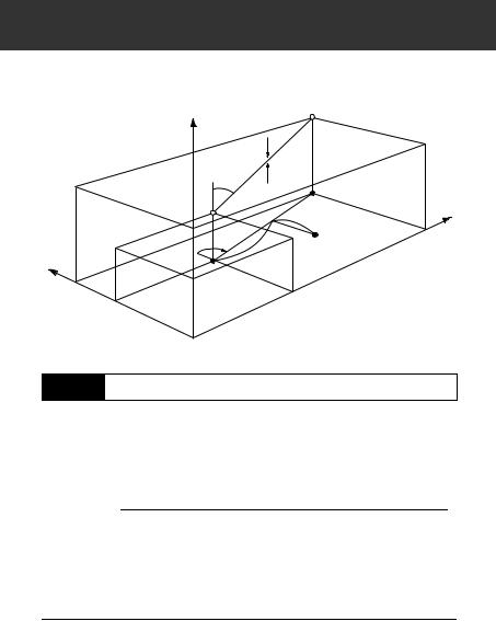
15. SETTING-OUT LINE
Setting-out line is used for setting out a required point at a designated distance from the baseline and for finding the distance from the baseline to a measured point.
Z |
2nd Pt2nd. |
Pt. |
CutCut
Grade |
Fill |
|
|
Grade |
Fill |
|
|
|
|
|
|
1st Pt. |
|
|
|
1st Pt. |
Length |
Baseline |
E |
|
Baseline |
|
|
|
|
Offset |
|
Azimuth |
Length |
|
|
Azimuth |
Offset |
|
|
|
|
N
N
15.1Defining Baseline
To perform setting-out line measurement, first, define the baseline. The baseline can be defined by inputting the coordinates of the two points. The scale factor value is the difference between the input coordinates and the observed coordinates.
Scale (X, Y) = Hdist’ (horizontal distance calculated from the measured value)
Hdist (horizontal distance calculated from the input coordinates)
•When not observing first or second points, scale factor is set to “1”.
•Defined baseline can be used in both setting-out line measurement and point projection.
PROCEDURE
1.Allocate the  to the Meas mode screen.
“24.2 Allocating Key Functions”
60
15. SETTING-OUT LINE
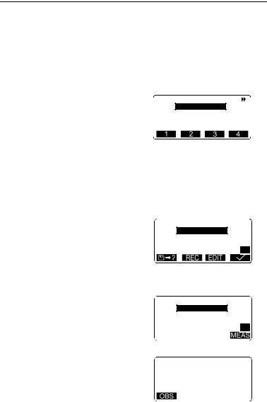
2.Press  to display <Set-out line>.
3.Enter the instrument station data.
“12.1 Entering Instrument
Station Data, PROCEDURE
Reading in Registered
Coordinate Data”.
4.Select “Define baseline” in <Setout line> and press  .
.
•When  is pressed, registered coordinates can be
recalled and used.
“12.1 Entering Instrument
Station Data, PROCEDURE
Reading in Registered
Coordinate Data”
5.Enter the first point data and press
{  }.
}.
6.Press {  } to move to the second point.
7.Press  and enter the second point data.
8.Press {FUNC}.
 is displayed.
• When not observing the first point and the second point, go to step 14.
9.Press  to move to observation of the first point.
Define 1st Pt. Np: 113.464 Ep: 91.088 Zp: 12.122
 Define 2nd Pt. Np: 112.706 Ep: 104.069 Zp: 11.775
P1
 Define 2nd Pt. Np: 112.706 Ep: 104.069 Zp: 11.775
P2
measure |
1st Pt. |
N |
113.464 |
E |
91.088 |
Z |
11.775 |
61
15. SETTING-OUT LINE
10.Sight the first point and press
 .
.
The measurement results are displayed on the screen.
•Press  to stop the measurement.
•You can input target height here.
11.Press  to use the measurement results of the first
point.
•Press  to observe the first point again.
12.Sight the second point and press
 .
.
13.Press  to use the measurement results of the second
point.
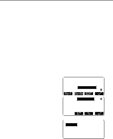
The distance between the two measured points, the distance calculated from inputting the coordinates of two points and the scale factors are displayed.
14.Press  to define the baseline. <Set-out line> is displayed. Move
to setting-line measurement.
“15.2 Setting-out Line Point”/
“15.3 Setting-out Line Line”
•Press  to set scale factor y to “1”.
•Press  to change the grade display mode to “1 : * * =
elevation: horizontal distance”.
Azimuth 93°20'31"
Hcalc 13.003m
Hmeas 13.004m
ScaleX 1.000091
ScaleY 1.000091
Grade %-2.669
Set-out line
Point
Line
62
15. SETTING-OUT LINE
•It is also possible to perform setting-out line measurement when  on page 2 of the Meas mode screen is pressed, then “Set-out line” is selected
without allocating the function key.
15.2Setting-out Line Point
Setting-out line point measurement can be used to find the required point coordinate by inputting the length and offset based on the baseline.
• Before performing setting-out line point, the baseline must be defined.
Y direction
Y direction
XXdirectiondirection
BaselineB li e
1st1stPtPt.. 2ndnd PtPt. .
LengthLength Offsetf t
RequiredReq i pointoint
PROCEDURE
1.Select “Point” in <Set-out line>
2.Press  .
.
Set the following items.
(1)Length: Distance along the baseline from the first point to the position at which a line extending from the required point intersects the baseline at right angles (X direction).
(2)Offset: Distance from the required point to the position at which a line extending from the required point intersects the baseline at right angles (Y direction).
Set-out line
Length 3.678m
Offset 1.456m
63
15. SETTING-OUT LINE
3.Press  . The coordinate value of the required point is calculated
and displayed.
• : records the coordinate value as a known point data.
Recording method:
“22.1 Registering/Deleting Known Point Data”
•Press  to move to settingout measurement of the required
point.
““14. SETTING-OUT
MEASUREMENT””
Set-out line
N |
111.796 |
E |
94.675 |
Z |
12.024 |
4.Press {ESC}. Continue the measurement (repeat steps from 4).
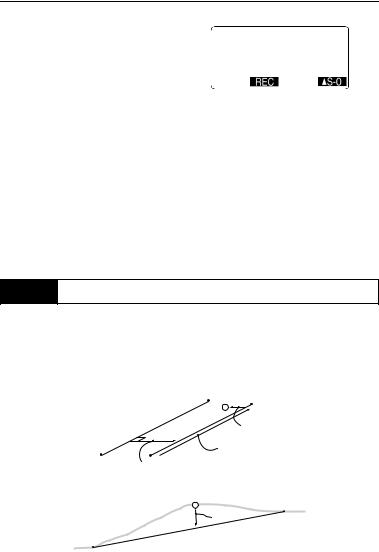
15.3Setting-out Line Line
Setting-out line line measurement tells how far horizontally the measured point is from the baseline and how far vertically the measured point is from the connected line. The baseline can be offset in a horizontal direction if necessary.
• Before performing setting-out line line, the baseline must be defined.
Profile View
Profile View
Measured Pointi t
Baseline |
|
Offline ((----) ) |
|
Lengthth |
|
Offset (horizontalrizontal direction)direction) |
|
Measured Point |
|
Measured Point |
|
Cut |
2nd Ptt.. |
Cut |
|
1stt Ptt..
64
15. SETTING-OUT LINE
PROCEDURE
1. Select “Line” in <Set-out line>.
2. Press |
and enter the offset |
line |
|
value. |
Set-out |
||
|
|
|
|
|
Offset |
|
m |
|
0.000 |
||
•Offset: How much to move the baseline.
Right side indicates positive value and left side indicates negative value.
•When not setting offset value, go to step 3.
3.Sight the target and press  . The measurement results are
displayed on the screen.
Press  to stop the measurement.
4.Press  to use the measurement results.
Displays the difference between the measured point and the baseline.
•Offline: A positive value indicates the point is on the right of the baseline and a negative value indicates it is on the left.
•“Cut” indicates that the point is below the baseline.
•“Fill” indicates that the point is above the baseline.
•Lenght: Distance along the baseline from the first point to the measured point.
•Press  to observe the target again.
Set-out line Offline -0.004m Cut 0.006m Length 11.775m
65

15. SETTING-OUT LINE
5.Sight the next target and press
 to continue the measurement.
•Press  : records measurement results.
Recording method:
““20. RECORDING DATA - RECORD MENU””
66