

14. SETTING-OUT MEASUREMENT
Setting-out measurement is used to set out the required point.
The difference between the previously input data to the instrument (the settingout data) and the measured value can be displayed by measuring the horizontal angle, distance or coordinates of the sighted point.
The horizontal angle difference and distance difference are calculated and displayed using the following formulae.
Horizontal angle difference
DHA = Horizontal angle of setting-out data - measured horizontal angle
Distance difference
Distance Displayed item
Sdist: S-OS = measured slope distance - slope distance of setting-out data
Hdist: S-OH = measured horizontal distance - horizontal distance of setting-out data Vdist: S-OV = measured height difference - height difference of setting-out data
•Setting out data can be input in various modes: slope distance, horizontal distance, height difference, coordinates and REM measurement.
•In slope distance, horizontal distance, height difference, and coordinate mode, registered coordinates can be recalled and used as setting-out coordinates. In slope distance, horizontal distance and height difference, S/H/V distances are calculated from the read in setting-out coordinate, instrument station data, instrument height, and target height.
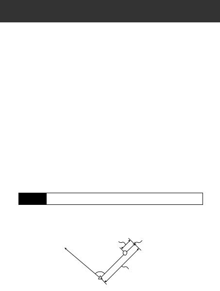
14.1Distance Setting-out Measurement
The point to be found based on the horizontal angle from the reference direction and the distance from the instrument station.
∆ distancedistance |
Position to be set out |
Position to be set out |
Reference direction
Reference direction
Present target |
|
|
|
|
|
|
|
Present target |
|
|
|
|
|
|
|
position |
|
|
|
|
|
|
t |
position |
|
|
|
|
|
|
u |
|
|
|
|
|
|
|
o |
|
|
|
|
|
|
t |
|
|
|
|
|
|
|
e |
out |
|
|
|
|
|
|
s |
|
|
|
|
|
|
e |
|
|
|
|
|
|
to b |
set |
|
|
|
|
|
e |
be |
|
|
|
|
|
cto |
|
|
|
|
|
|
n |
|
|
|
|
|
|
Instrument station |
ta |
|
|
|
|
|
|
is |
|
|
|
|
|
|
|
Instrument station |
|
|
|
|
|
|
|
D |
|
|
|
|
|
|
|
|
Distance |
|
|
|
|
|
|
52
14. SETTING-OUT MEASUREMENT
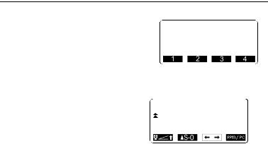
PROCEDURE
1.Press  in the third page of the Meas mode screen to display
<S-O>.
2.Enter the instrument station data.
“12.1 Entering Instrument
Station Data, PROCEDURE
Reading in Registered
Coordinate Data”.
3.Set the azimuth angle of the backsight point.
“12.2 Azimuth Angle Setting",
steps 2 to 6.
4. Select “S-O data.”
S-O S |
|
|
|
Sdist: |
|
|
m |
|
0.000 |
||
H ang: |
0°00'00" |
|
|
5.Press  to select the display mode with the same distance value
set in step 4.
Each time  is pressed: S-O S (slope distance), S-O H (horizontal
distance), S-O V (height difference), S-O (coordinates), S-O Ht. (REM measurement).
“14.2 Coordinates Setting-out
Measurement”, “14.3 REM
Setting-out Measurement”
•When  is pressed, registered coordinates can be
recalled and used. Distance and angle are calculated using the coordinate value.
“12.1 Entering Instrument
Station Data, PROCEDURE
Reading in Registered
Coordinate Data”
53
14. SETTING-OUT MEASUREMENT
6.Press  and set the following items.
(1)Sdist/Hdist/Vdist: distance from the instrument station to the position to be set out.
(2)H ang: included angle between the direction of the reference and the point to be set out.
•Pressing  in the second page allows you to enter the
coordinates of the point to be set out.
7.Press  to set the input values.
8.Rotate the top of the instrument until “dHA” is 0° and place the target on the sight line.
9.Press  to start distance measurement. The target and the
distance of the point to be set out is displayed (S-O H).
S-O H |
|
|
|
|
|
Hdist |
: |
3.300m |
|||
H ang |
|
|
|
|
|
:40 |
|
|
|
||
|
|
|
|
P1 |
|
|
|
|
|
|
|
|
|
|
|
|
|
S-O H |
|
|
Hdist |
: |
|
3.300m |
||
H ang |
|
:40°00'00" |
P2
S-O H |
0.820m |
dHA |
0°09'40" |
H |
2.480m |
ZA |
75°20'30" |
HAR |
39°05'20" |
54
14. SETTING-OUT MEASUREMENT
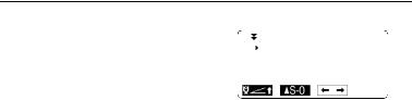
10.Move the prism forward and backward until the setting-out
distance is 0m. If  is "+", move the prism toward yourself, if it
is "-", move the prism away from yourself.
•By pressing  , an arrow pointing to the left or right
displays which direction the target should be moved.
←: Move the prism to left.
→: Move the prism to right.
↓ : Move the prism forward.
↑ : Move the prism away.
When the target is within measurement range, all four arrows are displayed.
11.Press ESC to return to <S-O>.
•When  was used in step 5, the list of registered coordinates
is restored. Continue setting-out measurement.
• : records measurement results
Recording method:
““20. RECORDING DATA - RECORD MENU””
↑ ↓ |
0.010m |
←→ |
0°00'30" |
H |
2.290m |
ZA |
75°20'30" |
HAR |
39°59'30" |
•It is possible to perform setting-out measurement when  on the second page of Meas Mode is pressed, then "S-O" is selected.
55
14.SETTING-OUT MEASUREMENT
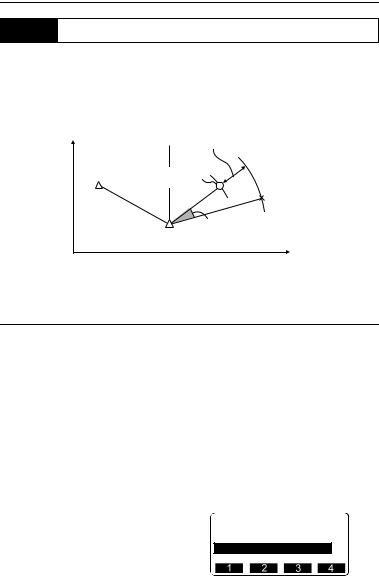
14.2Coordinates Setting-out Measurement
After setting the coordinates for the point to be set out, the SET calculates the setting-out horizontal angle and horizontal distance. By selecting the horizontal angle and then the horizontal distance setting-out functions, the required coordinate location can be set out.
N |
0 |
∆ distance |
|
Back sight |
|
∆ Distance |
|
|
|
||
station |
|
|
|
Back sight |
Present target |
||
station |
|||
Present target |
|||
|
position |
||
|
position |
|
|
|
|
Point to be set out |
|
|
|
Point to be set out |
|
|
|
Angle∆ Angle |
|
|
station |
|
|
InstrumentI strument station |
|||
|
|
E |
|
•To find the Z coordinate, attach the target to a pole etc. with the same target height.
PROCEDURE
1.Press  on the third page of the Meas mode screen to display
<S-O>.
2.Enter the instrument station data.
12.1 Entering Instrument Station
Data PROCEDURE Reading in
Registered Coordinate Data”.
3.Set the azimuth angle of the backsight point.
“12.2 Azimuth Angle Setting”,
steps 2 to 6.
4.Select "S-O data" and press  until <S-O Coord> is displayed.
S-O
Np: 100.000
Ep: 100.000
Zp: 50.000
Tgt.h 1.400m
56
14. SETTING-OUT MEASUREMENT
5.Press  . Enter the coordinates of the setting-out point.
•When  is pressed, registered coordinates can be
recalled and used as setting-out coordinates.
“12.1 Entering Instrument
Station Data”
6.Press  to set the setting-out data.
7.Press  to begin coordinate setting-out measurement.
Move the prism to find the point to be set out.
 : Move the prism upward.
 : Move the prism downward.
8.Press {ESC} to return to <S-O>.
When  was used in step 5, the list of registered coordinates is
restored. Continue setting-out measurement.
S-O |
100.000 |
|
Np: |
|
|
Ep: |
100.000 |
|
Zp: |
50.000 |
|
Tgt.h |
1.400m |
P1 |
↓ |
1.988m |
→ |
2.015m |
ZA |
-1.051m |
89°52'50" |
|
HAR |
150°16'10" |
57
14.SETTING-OUT MEASUREMENT
14.3REM Setting-out Measurement
To find a point where a target cannot be directly installed, perform REM settingout measurement.
“11.4 REM Measurement”
PROCEDURE
1.Install a target directly below or directly above the point to be found, then use a measuring tape etc. to measure the target height (height from the surveying point to the target).
2.Press  in the Meas mode screen to display <S-O>.
3.Enter the instrument station data.
“12.1 Entering Instrument
Station Data, PROCEDURE
Reading in Registered
Coordinate Data”.
4.Select “S-O data” and press  until <S-O Ht.> is displayed.
5.Press  .
.
Input height from the surveying point to the position to be set out in "SO dist".
6.After inputting the data, press
 .
.
S-O Ht
Height: 3.300m
58
14. SETTING-OUT MEASUREMENT
7.Press  to begin REM settingout measurement.
Move the telescope to find the point to be set out.
“14.1 Distance Setting-out Measurement” steps 9 to 10
 : Move the telescope near the zenith.
 : Move the telescope near the nadir.
8.When the measurement is completed, press {ESC} to restore <S-O>.
|
|
|
1.051m |
|
|
|
0°01'00" |
S |
1.051m |
||
ZA |
89°52'55" |
||
HAR |
150°16'10" |
||
59