

Учебное пособие 2131
.pdfIssue № 1(33), 2017 |
ISSN 2542-0526 |
UDC625.7.8
O. A. Sotnikova1
RADIATIVE HEAT EXCHANGE IN HEAT GENERATORS
WITH VORTEX FURNACES
Voronezh State Technical University
Russia, Voronezh, tel.: (473) 277-43-39, e-mail: hundred@vgasu.vrn.ru
1D. Sc. in Engineering, Prof. of the Dept. of Design of Buildings and Structures Named after N. V. Troitsky
Statement of the problem. Vortex motion of smoke gases in a furnace allows one to achieve a uniform temperature distribution within a furnace. Thus processes of heat transfer grow more intense and the reliability of boiler and longevity increases. Vortex principle of burning of fuel leads to rotational speeds, which reduces the expenditure component of the vector of the absolute velocity of smoke gases in the combustion chamber of boilers. Thisin turn leads to a reduction in the heat losses fromchemical and mechanical underburning due to keeping hot gases in a combustion chamber for longer.
Results. An attempt was made to create a vortex furnace of the boiler and the approximate method of its calculation including radiative heat transfer Established in the combustion chamber rotational speeds reduces the expenditure component of the vector of absolute velocity, which leads to an increase in the residence time of hot gases in the combustion chamber and reduce heat loss as chemical and mechanical underburning.
Conclusions. Analytical studies were performed which enabled us to obtain the equations to determine the local angular radiation coefficients of linear source on an elementary area for its different locations: on a horizontal, vertical and inclined heat transfer surface. The analytical expressions are complementary to the known data on the angular radiation coefficients and significantly enhance the radiative heat transfer calculation in the vortex boiler furnaces. The use of vortex burners will allow one to increase the intensity of heat transfer, and increase the longevity of a boiler by providing a uniform temperature distribution within the furnace and to reduce capital and operating costs.
Keywords: radiative heat transfer, angular coefficient of radiation, heat, boiler, vortex furnace, heat exchange, heat transfer.
Introduction
Decentralized and autonomous heat supply typically has relatively short main pipes or none at all, small fuel transportation costs and thus low heat losses and economic efficiency. These systems employ vapour and water-heating boilers. There have been found a few factors that influence the operation in fire chambers.
© Sotnikova О. А., 2017
31

Russian journal of building construction and architecture
Significant thermal losses of a fire chamber call for activities to protect screen surfaces from heating excessively in particular. In practice inside a fire chamber there are local deviations of the temperature with them being as high as a few hudnred degrees. Resulting thermal unevenness are a cause of burnouts and lead to lower efficiency of a chamber. Therefore addressing this problem is currently of importance [1—15].
One of the ways to do that is to apply the whirlwind principle of fuel combustion. It means that using a relevant way of supply in a fire chamber there is a whirl flow of reacting fuel and oxidizer particles.
The twisted shape of a flow in space is reached by a tangential introduction of a fuel-air mix into a chamber. Rotation speeds reduce the consumption of an absolute speed, which results in an increase in how long hot gases stay in a fire chamber and a drop in losses in a chemical and mechanical underburning. A large speed and a high turbulization of a twisted torch cause an increase in the coefficient of gas heat transfer to heated surfaces thus improving the coefficient of efficiency of a chamber.
We have attempted to design a twisted fire chamber and its approximate calculation method as well as for radiative heat exchange. It is mainly used in fire chambers. Heat flows from a gas, fuel, powdered-coal torch contain 85—95 % from a radiative flow and 10—15 % from a convective flow.
1. Determining total integral heat flows and radiation angular coefficients. According to the method by A. N. Makarov [1], total integral heat flows consisting of radiations falling on a heated surface from a torch, wall lining, lid and convective flows. The density of an integral flow falling on the i-th elementary area of a heated surface is determined using the expression
qin qin.ф qin.оф qin.п qin.о.п qiкон , |
(1) |
where qin. t is the density of an integral radiation flow falling on the i-th area from a torch considering the radiation absorption of a torch; qin. оф is the same for a flow generated by the reflection of radiaiton of a torch from the walls, floor and lid; qin. п is the same for a flow of radiating walls, floor, lid considering the reflection and absorption of radiation; qin. о. п is the same for a flow generated by the reflection of radiation from the surfaces of the walls, floor, lid; qiкон is the density of a convective flow per an area.
The most difficult issue with applying this method is determining the angular coefficients. In practice analytical expressions are necessary to identify the angular coefficients of radiation for a cylindrical source (e.g., a torch) and an elementary area in parallel and perpendicular planes.
32
Issue № 1(33), 2017 |
ISSN 2542-0526 |
The properties of constant rad iation of coaxial cylinders suggest that radiaiton of coaxial gas volumes can be substituted by an equivalent radiation of a cylindrical gas volume of a small diameter provided that it radiates power equal to the sum of those of radiation of coaxial cylindrical volumes. A radiating cylinder of a small diameter in thermal physics is traditionally called a linear source of radiation, which will be done further in our calcula tions.
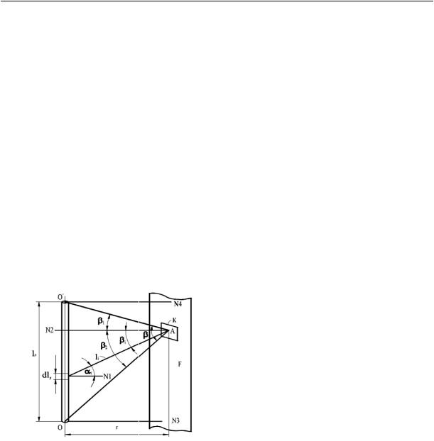
Let us determine a local angular coefficient of radiation of a cylindrical source of radiation on a surface of an elementary area К positioned between the normals N3 and N4 passing through the centre of the upper and lo wer circles of the base of a linear source of radiation (Fig. 1).
2. Geometric design for determining local angular coefficients of radiation for an elementary area on a plane F. An elementary area lies in a plane F parallel to an axis of a cylindrical source of radiation with the height lл. Let us point out an element dlл on the cylindrical source. As a cylindrical linnear source of radiation is a cylinder of an infinitely small diameter, an element dlл is an ele mentary cylinder, i.e. a cylinder of an infinitely small diameter and an infinitely small height dlл.
Fig. 1. Geometric designs for determining local angular coefficients of radiation of a linear source on an elementary area for its position in mutually parallel planes
An elementary angular coefficient of radiation d ik from a surface of an elementary area is given by the expression
d |
|
|
cos i cos iFkdlл |
, |
(2) |
|
ik |
|
|||||
|
|
2l2l |
|
|
|
|
|
|
|
i |
л |
|
|
where i is an angle between a normalN1 to an axis of an elementary cylinder and a direction of radiation, degrees; i is the angle between the normal N2 to the centre of an elementary area and a direction of radiation, degrees; Fk is an area of an elementary area, m2; li is a distance from an elementary cylinder to an elementary area, m.
Let us designate the centre of an elementary area with А, a minimum distance from a point А to an axis of a cylinder with r. Let us draw rays АО and АО′ into the centre of a linear source of
33

Russian journal of building construction and architecture
radiation at a point А. Let us designate an angle between a straight line АN2 and a ray АО′ through 1, an angle between АN2 and a ray АО through 2. As seen from the designs, a linear source radiates into a point А within the angle with = 1 + 2.
A local angular coefficient of radiaiton of a linear source on a surface of an elementary area is given byintegratingthe expression (2) on theheightof a source of radiation:
ik |
cos |
cos F |
|
|||
|
i |
|
i k |
dlл . |
(3) |
|
|
2 |
2 |
|
|||
lл |
|
li |
lл |
|
||
In the expression (3) we have three variables. Using insertion, we will remove two out of three and in addition, integration on the height lл will be replaced by integration on an angle. According to Fig. 1, we have:
i i , cos i cos i , |
(4) |
|
cos i r /li , |
li r /cos i , |
(5) |
dli cos i |
lid . |
(6) |
Inserting (4)—(6) into (3) and integrating on an angle, we get an expression for determining a local angular coefficient of radiation of a linear source of radiation on an elementary area:
lk |
Fk |
|
sin cos( 1 2) , |
(7) |
2 |
|
|||
|
2 rl |
л |
|
|
|
|
|
||
where is an angle at which a linear source radiates on an elementary area, degrees. If an elementary area is positioned in a way that a normal N3 (or N4) passes through a point А, the expression (7) takes the following form:
|
|
Fk |
|
sin cos |
Fk |
|
|
|
1 |
|
|
||
lk |
|
|
|
|
|
|
|
|
|
|
sin2 . |
(8) |
|
2 |
rl |
|
2 |
rl |
|
2 |
|||||||
|
|
2 |
л |
2 |
л |
|
|
|
|||||
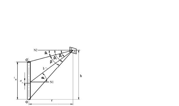
3. Geometric designs for determining local angular coefficients of radiation for an elementary area outside a plane F. In case if an elementary area is positioned outside a projection of a linear source of radiation on a plane F (Fig. 2), the calculation runs as follows.
Let the centre of an elementary area А be positioned at a distance h from a plane that passes through the base of a linear source of radiation with h > lл. An angle at which a linear source radiates on an elementary area is formed with rays АО and АО′ and is . Let us designate an angle between a normal N2 at a point А and a ray АО through 1, an angle between N2 and a ray АО′ through 2.
Fig. 2 suggests that according to the expression (4)—(6), these are appropriate for an elementary area and a linear source of radiation. For determining a local coefficient of radiaiton of a
34
Issue № 1(33), 2017 |
ISSN 2542-0526 |
linear source on an elementary area let us insert (4)—(6) into (2) and integrate the resulting expression within an angle :
lk |
Fk |
|
sin cos( 1 2) . |
(9) |
2 |
|
|||
|
2 rl |
л |
|
|
|
|
|
||
Fig. 2. Geometric designs for determining local angular coefficients of radiation for an elementary area on a vertical plane at a random height
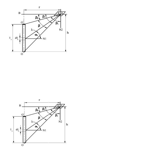
4. Geometric design for determining local angular coefficients of radiation of linear source on an elementary area for their position in mutually perpendicular planes. Let us examine a mutually perpendicular position of planes where there are linear sources of radiation and an elementary area. Let a plane where an elementary area is passes through the base of a linear source of radiation (Fig. 3). Let a shortest distance from a linear source to a point А — r, a normal to the centre of an elementary area be N2, an angle at which a linear source radiates on a point А — ОАО' = . An elementary angular coefficient of radiation dlл on an elementary area is given by the expression (2). A local angular coefficient of radiation of a linear source on an area is identified using integration of the expression (2) on the heig ht of a linear source or after corresponding insertions on an angle β.
Based on Fig. 3, we have:
cos i cos i , |
(10) |
|
li |
r /cos i , |
(11) |
dli |
cos i lid . |
(12) |
Inserting (10)—(12) into (2) and integrating the resulting expression within an angle α, we get an analytical expression for calculating a local angular coefficient of radiaiton of a linear source on an elementary area positioned in a perpendicular plane:
|
|
|
Fk |
|
sin2 . |
(13) |
lk |
2 2rl |
|
||||
|
|
л |
|
|||
|
|
|
|
|
||
35
Russian journal of building construction and architecture
Fig. 3. Geometric designs for determining local angular coefficients of radiaiton of a linear source on an elementary area for their position in mutually perpendicular planes
5. Geometric designs for determining local angular coefficients of radiation for an elementary area on a horizontal plane at a random height. For a position of an elementary area at any random height h from the lower (or upper) base of a linear source we have the following geometric designs (Fig. 4). The shortest distance from point А to a linear source is r. Let us designate ОАО' = , ОАВ = 1, О'АВ = 2, 1 - 2 = .
Fig. 4. Geometric designs for determining local angular coefficients of radiaiton for an elementary area on a horizontal plane ata random height
Fig. 4 suggests that for the equation (10)—(12) mutual positions of a linear source and an elementary area are appropriate. For determining a local angular coefficient of radiation of a linear source on an elementary area it is necessary to insert (10)—(12) into (2) and integrate within changes of an angle αi, i.e from 2 to 1:
lk |
Fk |
|
sin2 1 sin2 2 . |
(14) |
2 |
|
|||
|
2 rl |
л |
|
|
Average angular coefficients of radiation of a linear source on a flat surface F (see Fig. 1) lF are determined as a sum of local angular coefficients of radiation of a linear source on elementary areas on a surface F:
|
n |
|
lF |
lk , |
(15) |
|
1 |
|
where n is the number of elementary areas on a F.
36

Issue № 1(33), 2017 |
ISSN 2542-0526 |
The expressions for determining a local angular coefficient of radiation of a linear source on a surface of an elementary area positioned on random planes are obtained identically.
Energy setups with twisted fire chambers used for heat supply of buildings and structures allow an even temperature distribution in fire chambers and thus improving their life cycle.
Conclusions
1.Rotation speeds in a fire chamber decrease the consumption of a vector of absolute speed resulting in hot gases staying longer in a fire chamber and smaller heat losses for a chemical and mechanical underburning.
2.The use of twisted fire chambers intensifies heat transfer as well as increases the durability of a fire chamber by means of even temperature distribution within a fire chamber and reduces maintenance costs.
3.Based on the analytical studies, equations for determining local angular coefficients of radiation of a linear source on an elementary area for its position on horizontal, vertical, slope surfaces of heat transfer. The obtained analytical expressions supplement the available data on angular coefficients and enable new methods of calculating radiation heat transfer in twisted fire chambers.
References
1.Babich A. S., Kirnova M. A., Sotnikova K. N. Razrabotka algoritma optimizacii rashoda topliva istochnikom teploty [Development of algorithm optimization of fuel consumption by the heat source].
Inzhenernye sistemy i sooruzheniya, 2009, no. 1, pp. 125––131.
2.Makarov A. N. Teoriya i praktika teploobmena v elektrodugovykh i fakel'nykh pechakh, topkakh, kamerakh sgoraniya: v 2 ch. Ch. 2. Teploobmen v fakel'nykh pechakh, topkakh, kamerakh sgoraniya [Theory and practice of heat exchange in electric arc and torch furnaces, fire chambers, combustion chambers: in 2 parts. Part 2. Heat transfer in torch furnaces, fire chambers, combustion chambers]. Tver, TGTU, 2009. 152 p.
3.Chudinov D. M. [i dr.]. Razrabotka novykh intellektual'nykh svetoprozrachnykh ograzhdayushchikh konstruktsiy zdaniy [The development of new intellectual translucent enclosing structures of buildings].
Inzhenernye sistemy i sooruzheniya, 2010, no. 1, pp. 93––97.
4.Sotnikova K. N., Muratov A. V. Avtomatizatsiya protsessa upravleniya teplovymi potokami v pomeshcheniyakh [Automated process control of heat fluxes in the premises]. Vestnik Voronezhskogo gosudarstvennogo tekhnicheskogo universiteta, 2008, no. 12, pp. 48––50.
5.Sotnikova K. N., Kolosova N. V., Drapalyuk R. A. Modelirovanie gibridnoy ekspertnoy sistemy dlya proektirovaniya zdaniy «zelenogo stroitel'stva» [Modelling hybrid expert system for building design "green building"]. Inzhenernye sistemy i sooruzheniya, 2012, no. 2, pp. 105––113.
6.Sotnikova K. N. Povyshenie effektivnosti energosnabzheniya potrebiteley v sistemakh s netraditsionnymi istochnikami teploty [Improving the efficiency of power supply in systems with untraditional heat sources].
Vestnik Voronezhskogo gosudarstvennogo tekhnicheskogo universiteta, 2009, no. 4, pp. 66––71.
37

Russian journal of building construction and architecture
7.Sotnikova K. N. Razrabotka modeli sinteza sostava traditsionnykh sistem teplosnabzheniya s ispol'zovaniem vozobnovlyaemykh istochnikov energii [Development of a model for the synthesis of the composition of traditional heating systems using renewable energy sources]. Nauchnyy vestnik Voronezhskogo GASU. Stroitel'stvo i arkhitektura, 2009, no. 3, pp. 25––31.
8.Sotnikova O. A., Cherenkov S. I. Obosnovanie perspektivnykh napravleniy snizheniya intensivnosti korrozii teploobmennykh poverkhnostey kotlov teplogeneriruyushchikh ustanovok sistem teplosnabzheniya [Substantiation of perspective directions of reduction of the intensity of corrosion of the heat transfer surfaces of boilers heat generating installations heat supply systems]. Inzhenernye sistemy i sooruzheniya, 2009, no. 1, pp. 99––107.
9.Sotnikova O. A., Petrikeeva N. A. Raschet ekonomicheskoy effektivnosti primeneniya kondensatsionnykh teploobmennykh ustroystv teplogeneriruyushchikh ustanovok [The calculation of economic efficiency of use of condensing heat exchangers thermal generating plants]. Nauchnyy vestnik Voronezhskogo GASU. Stroitel'stvo i arkhitektura, 2008, no. 1, pp. 113––117.
10.Sotnikova O. A., Petrikeeva N. A., Turbin V. S. Matematicheskaya model' protsessov kondensatsii vodyanykh parov na teploobmennykh poverkhnostyakh [Mathematical model of the processes of condensation of water vapor on heat transfer surfaces]. Izvestiya Tul'skogo gosudarstvennogo universiteta. Stroitel'stvo, arkhitektura i restavratsiya, 2006, no. 10, p. 159.
11.Sotnikova O. A., Cherenkov C. I. Obosnovanie perspektivnykh napravleniy snizheniya intensivnosti korrozii teploobmennykh poverkhnostey kotlov teplogeneriruyushchikh ustanovok sistem teplosnabzheniya [Substantiation of perspective directions of reduction of the intensity of corrosion of the heat transfer surfaces of boilers heat generating installations heat supply systems]. Inzhenernye sistemy i sooruzheniya, 2009, no. 1, pp. 99––107.
12.Sotnikova O. A., Chudinov D. M., Kolosov A. I. Primenenie netraditsionnykh vozobnovlyaemykh istochnikov energii pri reshenii problem energosnabzheniya i ekologicheskoy bezopasnosti [The use of renewable energy in addressing energy and environmental security]. Inzhenernye sistemy i sooruzheniya, 2009, no. 1, pp. 80––87.
13.Sotnikova O. A., Bulygina S. G. Ekologicheskaya bezopasnost' ventiliruemykh pomeshcheniy restorannykh kompleksov [Environmental safety of ventilated premises of restaurant complexes]. Nauchnyy vestnik Voronezhskogo GASU. Stroitel'stvo i arkhitektura, 2012, no. 1, pp. 154––163.
14.Turbin V. S., Sotnikova O. A., Petrikeeva N. A. Razrabotka matematicheskoy modeli teplomassoobmena v napornykh teploutilizatorakh [Development of mathematical model of heat and mass transfer in the pressure recovery]. Vestnik Voronezhskogo gosudarstvennogo tekhnicheskogo universiteta, 2005, vol. 1, no. 6, p. 79.
15.Sazonov E. V. [i dr.]. Effektivnost' szhiganiya tverdykh bytovykh otkhodov v modul'nykh ustanovkakh sistem detsentralizovannogo teplosnabzheniya [The efficiency of combustion of solid waste in modular installations of systems of decentralized heat supply]. Izvestiya vuzov. Stroitel'stvo, 2006, no. 2, pp. 68––73.
16.Durbin P. A. Separated Flow Computations with K-S-O-Model. AIAA J, 1995, vol. 33, no. 4, pp. 659—664.
17.Edwards D. К. Molecular Gas Band Radiation. Advanes in Heat Transfer, 1976, vol. 12, pp. 115—193.
18.Hubbard G. L., Tien C. L. Infrared Mean Absorption Coefficients of Luminous Flames and Smoke. J. Heat Transfer, 1978, vol. 100, pp. 235—239.
19.Mengiic M. P., Viscanta R. On the Radiative Properties of Polydispersions: a Simplified Approach. Combast. Sci. and Technol, 1985, vol. 44, no. 3, 4, pp. 143—159.
20.Tomeczek J., Weber R. Radiation and Burner Geometry in the Mathematical Modeling of a Flat Gaseous Flame. Combast. and Flame, 1981, vol. 41, no. 2, pp. 149—156.
38

Issue № 1(33), 2017 ISSN 2542-0526
DESIGNING AND CONSTRUCTION OF ROADS,SUBWAYS,
AIRFIELDS,BRIDGES AND TRANSPORT TUNNELS
UDC 625.7/691.16
M. N. Panevin1, Yu. I. Kalgin2
ORGANOMINERAL MIXES BASED ON AN ASPHALT CHIP
FOR SURFACINGS AND SUBBASES OF HIGHWAYS
Ltd. «AVTODORIS»
Russia, Voronezh, e-mail: panevinn@mail.ru 1Engineer
Voronezh State Technical University
Russia, Voronezh, tel.: (473) 236-18-89, e-mail: kalgin36@yandex.ru
2D. Sc. in Engineering, Prof. of the Dept. of Construction and Operation of Highways
Statement of the problem. The problem of the development of organic-compounds characterized by the use of a mineral asphalt chip in part, to the device structural pavement layers.
Results. The results of the experiment and mathematical analysis to determine the physical and mechanical properties of organic-mineral mixes are shown. The operation of physical and mechanical and technological properties of organic-mineral mixes with different proportions of asphalt chip in the mineral part. The role of asphalt chip in improving the quality using organiccompounds. The optimum compositions of organic compounds using asphalt chips in the mineral part and the optimal characteristics of the materials for making them are presented.
Conclusions. The main factor influencing the characteristics of the organic mineral mix is the amount of bituminous emulsion making up a complex binder. Increasing the content of cement in the binder with a minimum content of the emulsion has a less significant effect on the properties of the mix. The ptimal content of asphalt chip is 40 % in the mineral part of the mix.
Keywords: asphalt concrete, asphalt chip, organic mixture, bituminous emulsion.
Introduction
Life cycle and transport and operational properties of highways can be improved by using modern technologies in their construction, reconstruction and maintenance [2, 5, 6, 12—15]. Organic and mineral mixes are one of the most effective materials used for roadways [3, 7, 10, 11].
© Panevin M. N., Kalgin Yu. I., 2017
39

Russian journal of building construction and architecture
The use of organic and mineral mixes in road construction has a few significant technological, economic and operational advantages [17—19] such as cutting-edge technology of material production to provide smoothness and roughness of a road surface, efficient and quick maintenance, reliability, possibleuse of localmaterials andsecondaryresources and primarilygranular asphalt. Granular asphalt is a loose material consisting of mineral components and an organic binder making it good for secondary use. It becomes most cost-effective if used for asphalt concrete and organic and mineral mixes. The use of granulates of old asphalt in road construction in Russia allows one to lower a demand for mineral and binding materials and reduce the total costs of their components enabling asphalt and concrete wastes to be recycled as part of the environment-friendly effort [7—11].
According to the European Asphalt Pavement Association (EAPA), there is an annual increase in the use of granular asphalt for hot and cold asphalt concrete and bituminous mineral mixes [4, 8, 9]. In Japan 98 % of granular asphalt is used in asphalt concrete mixes [4].
1. Optimization of compositions and properties of organic and mineral mixes using a regression model of their mutual dependence. In order to develop the optimal compositions of organic and mineral mixes using complex binders and secondary road industry materials, an experiment was carried out using the methods of mathematical planning [1]. It is assumed that strength and operational properties of organic and mineral mixes are completely due to their composition. The components and their proportions in a mix may fluctuate as so do the conditions for solidification such as temperature and humidity. There might also be errors in measuring the water resistance or strength limit. Let us denote the numerical value of the characteristics in question as Y and its functional dependence on the parameters as F(X1, X2, X3). Random excitation in each of the experiments is expressed through an additive Z:
Y F(X1,X2,X3) Z , |
(1) |
where according to the central limit theoreme, the random value Z has a normal distribution with the parameters M(Z) = 0 and σ(Z) = σ. Taking the mathematical expectation M from both parts, we get
M(Y) M(F(X1,X2,X3 Z)) F(X1,X2,X3) M(Z) F(X1,X2,X3). (2) The last equality means that the initial functional bond F (X1, X2, X3) expresses not Y itseld but its mathematical expectation for the specified parameters X1, X2, X3:
M(Y) F(X1,X2,X3), |
(3) |
Such a dependence is regressional and the law F(X1, X2, X3) is a regression of Y along X1, X2, X3. There is a well-developed method for obtaining a regression dependence based on experimental
40