

Учебное пособие 2112
.pdfIssue № 1(29), 2016 |
|
ISSN 2075-0811 |
Fig. 5. Coefficient of the reinforcement of the truss p*(n), determined using the condition
0 = 2
A specific value of this parameter can be identified
lim p* |
c3 |
h3 |
. |
|
d3 |
3a3 |
|||
n |
|
Conclusions. The major outc ome of the paper is obtaining the formula for the dependence of the deflection on t e number f slabs. This has two implication s. The first one is bridg ing “the dimensi on curse”. A drop of accuracy (sometimes significant drop) ham pering the calculations using systems with a large number of rods cau ses an individual in c harge of calculation and design to resor t to accura e formulas that are first not alwa ys available to use and secondly do not account for all the parameters of a syste m. All the parameters cannot pos sibly be accounted for. Ho wever in this paper the result (formula) apart from ob ious param eters of load, sizes and rig dity also contains coefficients of redistribut on of the sections of the areas of the belts g and p . Furtherm ore, it conta ins the num ber of slabs of the truss n. An elementary calculation of a deflection of a truss with a final n mber of slabs is nothing but an ordinary equation from a un iversity Construction Mechanics course eve n if the solu tion is searched for in a sy bolic form . Induction generalization of the result on a random nu mber of slabs is not generally possible or is so elaborate that the outcome is unfath omable and impractical. In this task we did get this kind of a solution. T he second implication of the for mula has to do with testing. For compl ex and costly computational packages a brie f testing ensures high accuracy of calcu lations.
Here for a girder truss with declining braces where an even load is appli ed to its lo wer belt, the for ula for the deflection of the mid le of the s an depending on the size of a truss, num-
91

Scientific Herald of the Voronezh State University of Architecture and Civil Engineering. Construction and Architecture
ber of spans and load was obtained. The comparison employing analytical formulas for the deflections of trusses with other lattices showed that the ratio of the deflections may vary depending on the size and number of spans. Some specific ratios of the deflections of trusses have been found. A typical inhomogeneity of the dependence of the deflection on the number of slabs is highlighted.
References
1.Kirsanov, M. N. Induktivnyj metod resheniya statiki i dinamiki sterzhnevyx sistem / M. N. Kirsanov // Mezhdunarodnyj forum informatizacii. MFI—2001. — S. 163—166.
2.Kirsanov, M. N. Izgib, kruchenie i asimptoticheskij analiz prostranstvennoj sterzhnevoj konsoli / M. N. Kirsanov // Inzhenerno-stroitel'nyj zhurnal. — 2014. — № 5 (49). — S. 37—43.
3.Kirsanov, M. N. Analiz progiba fermy pryamougol'nogo prostranstvennogo pokrytiya / M. N. Kirsanov // Inzhenerno-stroitel'nyj zhurnal. — 2015. — № 1 (53). — S. 32—38.
4.Reutov, D. O. Induktivnyj analiz progiba fermy regulyarnoj struktury v sisteme Maple / D. O. Reutov // Mezhdunarodnaya nauchno-prakticheskaya konferenciya ITON—2014. IV mezhdunar. nauch. seminar i mezhdunar. shkola po matematicheskomu modelirovaniyu v sistemax komp'yuternoj matematiki «KAZCAS—2014»: materialy konf. i tr. seminara. — Kazan': Foliant, 2014. — S. 256—261.
5.Axmedova, E. R. Chastotnoe uravnenie dlya ploskoj balochnoj fermy regulyarnoj struktury s treugol'noj reshetkoj / E. R. Axmedova, M. I. Kanatova // Mezhdunar. nauch.-prakt. konf. ITON—2014. IV mezhdunar. nauch. seminar i mezhdunar. shkola po matematicheskomu modelirovaniyu v sistemax komp'yuternoj matematiki «KAZCAS—2014»: materialy konf. i tr. seminara. — Kazan': Foliant, 2014. — S. 198—199.
6.Kirsanov, M. N. Induktivnyj analiz vliyaniya pogreshnosti montazha na zhestkost' i prochnost' ploskoj fermy/ M. N. Kirsanov // Inzhenerno-stroitel'nyj zhurnal. — 2012. — № 5 (31). — S. 38—42.
7.Dzabiev, A. A. Formuly dlya rascheta progiba arochnoj fermy / A. A. Dzabiev, S. P. Cherepanov // Voprosy obrazovaniya i nauki: teoreticheskij i metodicheskij aspekty: sb. nauch. tr. po materialam Mezhdunar. nauch.-prakt. konf., 31 maya 2014 g. Ch. 4. — Tambov: OOO «Konsaltingovaya kompaniya Yukom», 2014. — S. 63—64.
8.Zhaketov, D. D. Progib ploskoj balochnoj fermy s treugol'noj reshetkoj / D. D. Zhaketov, V. B. Yackov // Nauka i obrazovanie v XXI veke: sb. nauch. tr. po materialam Mezhdunar. nauch.-prakt. konf., 31 okt. 2014 g. Ch. 7. — Tambov: OOO «Konsaltingovaya kompaniya Yukom», 2014. — S. 34—36.
9.Kirsanov, M. N. Geneticheskij algoritm optimizacii sterzhnevyx sistem / M. N. Kirsanov // Stroitel'naya mexanika i raschet sooruzhenij. — № 2. — 2010. — S. 60—63.
10.Sonmez, M. Artificial Bee Colony algorithm for optimization of truss structures / M. Sonmez // Applied Soft Computing. — 2011. — Vol. 11. — P. 2406—2418.
11. Kirsanov, M. N. Skrytaya osobennost' i asimptoticheskie svojstva odnoj ploskoj balochnoj fermy / M. N. Kirsanov // Stroitel'naya mexanika i raschet sooruzhenij. — 2014. — № 4. — S. 9—12.
12.Hutchinson, R. G. Microarchitectured cellular solids — the hunt for statically determinate periodic trusses / R. G. Hutchinson, N. A. Fleck // ZAMM Z. Angew. Math. Mech. — 2005. — Vol. 85, N 9. — P. 607—617.
13.Kirsanov, M. N. Zadachi po teoreticheskoj mexanike s resheniyami v Maple 11 / M. N. Kirsanov. — M.: Fizmatlit, 2010. — 264 s.
92
Issue № 1(29), 2016 |
ISSN 2075-0811 |
14.Kirsanov, M. N. Maple i Maplet. Resheniya zadach mexaniki / M. N. Kirsanov. — SPb: Lan', 2012. — 512 c.
15.Goloshchapov, D.L. Synthesis of nanocrystalline hydroxyapatite by precipitation using hen's eggshell / D. L. Goloshchapov, V. M. Kashkarov, N. A. Rumyantseva, P. V. Seredin, A. S. Lenshin, B. L. Agapov, E. P. Domashevskaya // Ceramics International. 2013. Т. 39. № 4. С. 4539-4549.
16.Seredin, P.V. Strukturnye i opticheskie svojstva nizkotemperaturnyh mos-gidridnyh geterostruktur ALGAAS/GAAS (100) na osnove tverdyh rastvorov vychitanija / P. V. Seredin, A. V. Glotov, Je. P. Domashevskja, I. N. Arsent'ev, D.A. Vinokurov, A.L. Stankevich, I.S. Tarasov // Fizika i tehnika poluprovodnikov. 2009. T. 43. № 12. S. 1654-1661.
93

Scientific Herald of the Voronezh State University of Architecture and Civil Engineering. Construction and Architecture
UDC 624.014.078
V. V. Ledenev1, Chu Thi Hoang Anh2
DESIGN OF SEMI-RIGID CONNECTIONS OF A FOUNDATION BASE
WITH A METAL COLUMN
Tambov State Technical University
Russia, Tambov, tel.: (4752)63-03-80, e-mail: kzis@nnn.tstu.ru
1D. Sc. in Engineering, Prof. of Dept. of Building of Structures and Constructions
Hanoi Architectural University
Vietnam, Hanoi, e-mail: chuhoanganh2607@yahoo.com 2Lecturer (PhD student of Dept. of Building of Structures and Constructions Tambov State Technical University)
Statement of the problem. The connections of the metal column with the foundation are usually considered rigid or spin. Foreign researches proved that they are in intersidereal form (called flexible or semi-rigid connections). The additional strengths Q in a semi-rigid connection increase the load on the bolt in comparision with which in the relatively rigid connection. Prying strengths should be considered for the design of the semi-rigid connections.
Results. The calculations of foundation base of metal columns account the stiffness of all their elements. Three cases of fracture mechanism are considered and the design resistance of the components in all cases is calculated.
Conclusions. The article introduces a method for calculating the T-sub bolted base column of the frames, under bending moment and axial strength.
Keywords: semi-rigid connections, stiffness, resistant, prying strength, bolted T-stub connections, rotational stiffness, rotation, column, foundation.
Introduction
The European Standard [2] using experimental methods or methods of rigidity of a combination of members (component method) enables the determination of the load-carrying capacity of bolted joints, displacements and rotational angles in joints, etc. [6, 7, 9].
According to the method of rigidity of a combination of members, the rigidity of a column base depends on the rigidity and load-carrying capacity of members included in anchor bolts working on tension and shear; the support and Т-shaped slabs experiencing bending and tension; concrete foundation on compression and bending [5, 3, 8].
© Ledenev V. V., Chu Thi Hoang Anh, 2016
94
Issue № 1(29), 2016 |
ISSN 2075-0811 |
There are three cases of the failure of joints (Fig. 1):
––crushing of the slab and rupture of anchor bolts (Fig. 1а) — type 3;
––plastic failure of support slabs (Fig. 1b) — type 1;
––combination of the first two (Fig. 1c) — type 2.
1. Statement of the problem. Let us look at a column base of N-shaped section on a steel support slab joined to a concrete foundation by anchor bolts (Fig. 2). A joint is calculated considering the rigidity of members under the effect of a bending element and longitudinal strength [9].
The previously suggested method [3] is improved. Below are (Fig. 2) schemes of the operation of joining columns of N-shaped section to a steel support slab.
The failure of a support slab is due to plastic areas and hinges [2] (рис. 1, 3).
|
а) |
|
b) |
|
c) |
|
|
e |
|
|
|
|
|
|
n |
m |
|
|
|
|
|
Ft.Rd.3 |
|
Ft.Rd.1 |
|
Ft.Rd.2 |
|
Bt.Rd |
Bt.Rd |
B |
B |
Bt.Rd |
|
Bt.Rd |
|
Q |
|
t.Rd |
Q Q |
t.Rd |
Q |
|
|
|
|
|
||
|
|
|
t.Rd |
|
|
|
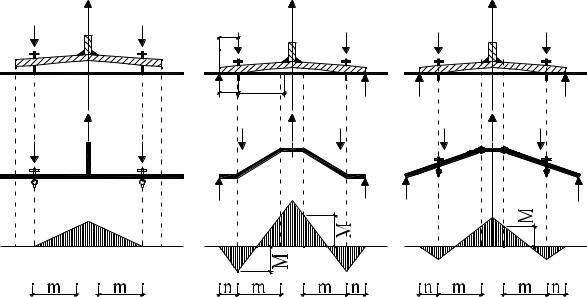
Fig. 1. Types of failure mechanisms, calculation schemes and diagrams of bending moments:
Ft, Rd,1 is the compressive resistance of joints corresponding to a plastic failure mechanism (Fig. 1b); Ft, Rd,2 is the compressive resistance of the joints corresponding with a type of a combination of failure mechanisms (Fig. 1c); Ft, Rd,3 is the compressive resistance of the joints corresponding with crushing of the slab and rupture of bolts; Mt, Rd is a plastic bending moment in the support slab (Fig. 1а);
Bt, Rd is a calculation compressive resistance of anchor bolts; B is a tensile strength on bolts; Q is extra strength [3]
95
Scientific Herald of t he Voronezh State University o f Architecture and Civil Engineering. Construction and Architecture
а) |
b) |
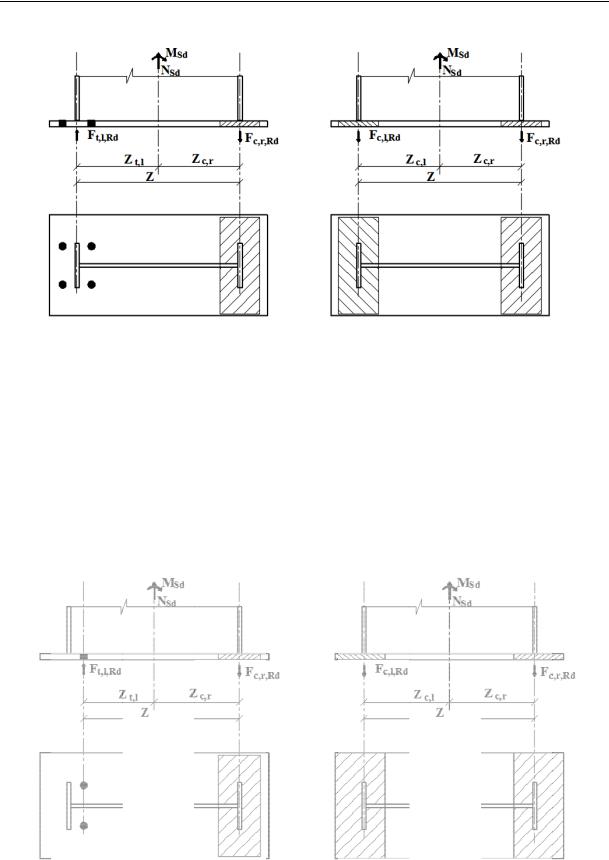
Fig. 2. Strengths applied to a support sla b:
а) two r ows of anchor bolts are stretched, the slab is compressed under the right cap; b) support slab is compressed under both c aps;
Ft, l, Rd is a tensile loa on the left part of the sup port slab;
is a compressive str ength on the right part of the support sla ;
|
Fc, l, Rd is a co mpressive strength on the left part of th |
support slab; |
||||
|
MSd is bending mo ment; NSd is a longitudinal strength; |
|||||
zc, l is an arm of the left compressive strength; zc, r is a n arm of the |
ight compressive strength; |
|||||
|
zt, l is an arm of the right tensile strength; z is |
n arm |
||||
( distance betw een the centres of the stretched and compressed zone s) |
||||||
|
c) |
d) |
||||
|
|
|
|
|
|
|
|
|
|
|
|
|
|
|
|
|
|
|
|
|
|
|
|
|
|
|
|
|
|
|
|
|
|
|
|
|
|
|
|
|
|
|
|
|
|
|
|
|
Fig. 2 (end). Strength applied to the support slab:
c)a r ow of anchor bolts is stretc hed, the slab is compressed under the right cap;
d)the same as “b” but the tension areas of the slab reach the edges
96
Issue № 1(29), 2016 |
ISSN 2075-0811 |
а) |
|
ep |
ep |
x |
|
x |
|
e) |
|
|
ep |
|
ep |
x |
|
|
ep |
b) |
f) |
c) |
g) |
d) |
h) |
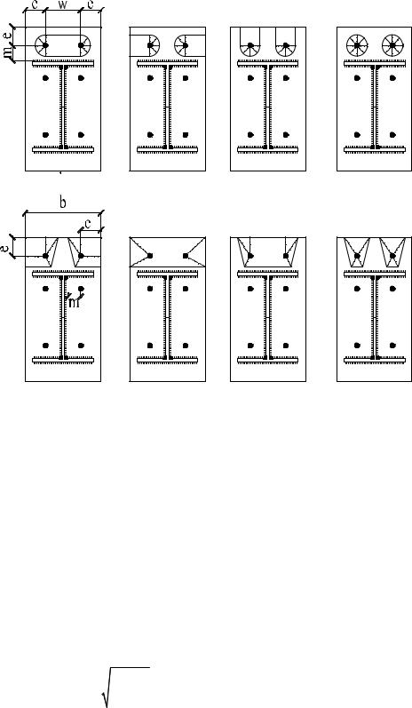
Fig. 3. Scheme of the failure of the support slab:
а, h) plastic areas are joined together; b) plastic areas reaches the transverse and longitudinal sides of the support slab;
c, g) the same for the transverse one; d) round plastic zones; e) angular plastic zones; f) rectangular plastic zones
2. Solution of the problem
2.1. Determining the compressive resistance of the joints as a minimum of the function [5, 7]:
|
|
|
Ft,Rd min FRd ,1, FRd ,2 , FRd ,3 . |
|
(1) |
||||||||
Considering extra forces at |
|
|
|
|
|
|
|
|
|
|
|
|
|
tp 2,07m 3 |
Ab |
|
tep : |
|
|
|
|
|
|
|
|||
|
|
|
|
|
|
|
|
|
|||||
|
|
Lbef leff |
|
|
|
|
|
|
|
|
(2) |
||
|
(8n 2d)M |
|
|
2M |
|
n |
F |
|
|||||
|
|
|
|
||||||||||
|
pl,1,Rd |
|
pl,2,Rd |
|
|
||||||||
Ft,Rd min |
|
|
|
|
; |
|
|
t,Rd |
; |
Ft,Rd ,b |
; |
||
|
|
|
|
|
|
|
|
|
|||||
|
2mn d (m n) |
|
m n |
|
|
||||||||
|
|
|
|
|
|
|
|
|
|
|
|
|
|
97

Scientific Herald of the Voronezh State University of Architecture and Civil Engineering. Construction and Architecture
without considering extra forces at
tp 2,07m3 |
Ab |
tep : |
|
||||
Lbef leff |
(3) |
||||||
|
|
|
|
||||
|
2M |
|
|
|
|||
pl,1,Rd |
|
||||||
Ft,Rd min |
|
|
; Ft,Rd ,b |
, |
|||
|
|
|
|||||
|
m |
|
|
|
|||
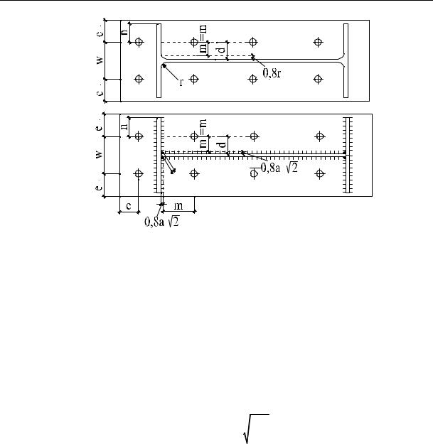
where m is the distance between plastic hinges and the axis of the bolt (for a welded column m ec 0,8ac 2 , ac is the height of the leg of the weld; ec is the distance between the axes of the compressed bolts to the column cap; for a rolled beam m ec 0,8r , n is the distance be-
tween the extra strength Q and axes of the bolts ≤1,25m); d is the diameter of the plate; Lbef is the effective length of anchor bolts:
Lbef 8db tg tep tn / 2,
where db is the diameter of anchor bolts; tg is the thickness of the base between the support slab and the upper one with the foundation base; tn is the thickness of the plate; Mpl,1, Rd, Mpl,2, Rd are plastic bending moments of the support slab corresponding to the first and second failure mechanisms:
|
l |
t2 |
f |
y,ep |
|
M pl,Rd |
eff |
ep |
|
, |
|
|
|
|
|
||
|
|
4 Mo |
|||
where leff is the effective length of the compressed zone of the support slab:
leff min 4m 1, 25ex ; 4 m; 0,5b; 2m 0,625ex 0,5w;2m 0,625ex eep ; 2 m 4eep ; 2 m w ;
tep is the thickness of the support slab; fy, ер is the bending resistance of the support slab material;
γМо is the coefficient: γМо = 1; w is the distance between two axes of bolts; b is the thickness of the support slab; ex, eep are geometrical characteristics (Fig. 3, 4); Ft, Rd, b is a calculated compressive resistance of anchor bolts:
FRd ,3 |
Ft,Rd ,b , Ft,Rd ,b |
0,9As fub |
; |
(4) |
|
||||
|
|
Mb |
|
|
As is the area of the longitudinal section of tensile bolts; fub is the tensile resistance of bolts; γМb = 1,1 is the coefficient.
98
Issue № 1(29), 2016 |
|
|
ISSN 2075-0811 |
а) |
|
ep |
|
ep |
|
|
|
|
|
c |
c |
ep |
|
c |
c |
|
|
||
|
|
|
|
b) |
|
ep |
|
ep |
|
|
|
|
|
c |
c |
|
c |
|
c |
ep |
a |
|
|
|
|
|
|
|
x |
2 |
|
|
c |
|
|
Fig. 4. Denotation of the sizes used in the calculation of the column: а) of a rolled section; b) of a welded section
2.2. Compressive resistance of the joints [1, 7]:
|
|
Mc,Rd |
|
|
|
|
|
|
|
|
|
Fс,Rd |
min f jbeff leff ,c ; |
|
|
, |
(5) |
|
|||||
|
|
hc tcf |
|
|
|
|
|
|
|
|
|
where fj is the compressive resistance of concrete under concentrated axial loads determined according to the European Standard [1]:
f j |
2k j fck |
; k j |
a b |
, |
|
|
1 1 |
||||
3 c |
ab |
||||
|
|
|
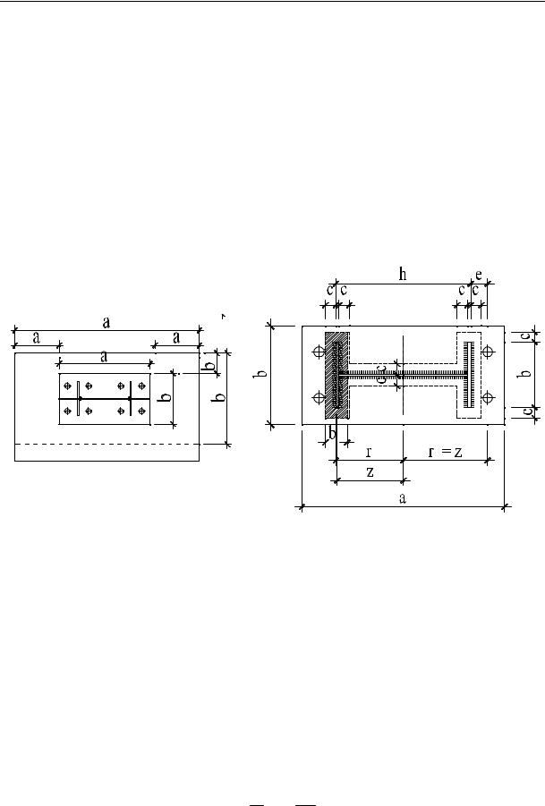
where fck is the compressive resistance of concrete; a, b is the width and length of the support slab (Fig. 5);
a1 min a 2ar ; 5a; a h; 5b1
b1 min a 2br ; 5b; b h; 5a1
h is the height of a concrete base plate; γс = 1,5; beff, с, leff, с the compressed zone of T-shaped section:
иa1 a;
иb1 b;
is the effective width and length of
A |
|
Fsd Ft ,Rd ,b |
, b |
|
Aeff ,c |
, l |
b 2c , |
|
|
||||||||
|
||||||||
eff ,c |
|
|
eff ,c |
|
b 2c |
eff ,c |
|
|
|
|
f j |
|
|
|
|||
99
Scientific Herald of the Voronezh State University of Architecture and Civil Engineering. Construction and Architecture
bc, c are the sizes specified according to Fig.5; Mc, Rd is a plastic moment in the column considering the shear and axial strengths (according to the European Standard [2]):
at e = Msd/Nsd > zc, r:
Mc,Rd min Ft,l,Rd z NSd zc,r ; Ft,l,Rd z NSd zt,l ; |
(6) |
at e = Msd/Nsd < zc, r: |
|
Mc,Rd min Fc,l,Rd z NSd zc,r ; Fc,r,Rd z NSd zc,l . |
(7) |
а)
|
1 |
r |
r |
|
r |
|
1 |
b) |
|
|
c |
|
c |
|
|
c |
eff |
|
|
c |
b |
b |
c |
|
|
Fig. 5. Sizes of the column base:
а) position of the column on the support slab; b) position of the effective compressed zone on the support slab
2.3. Bending resistance of the column base [1, 7]:
MRd Ft,Rd rb Aeff f j rc , |
(8) |
||
where rb is the distance between the axes of the tensile bolts to the neutral line: |
|
||
r |
hc e ; |
|
|
b |
2 |
c |
|
|
|
|
|
rc is the distance between the centre of the compressed zone to the neutral line:
rc h2c c b2eff .
100